
English Manual
Page 7
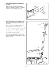
... in the lower end of the Frame (1), attach the Front Stabilizer (73) to the Main Wire (42). Tie the wire tie to the Frame with the wire tie. 73 74 1 Wire Tie 2 37 Wire Tie 42 1 7 Have a second person hold the Upright (2) and the Shield Cover (37) near the Frame (1). 3. Tip: To... prevent the Main Wire (42) from falling into the Upright (2), secure the Main Wire with two M10 x 85mm Screws (74). 4. Then, pull the upper end of the wire tie until the Main Wire is routed through the Upright. Orient the Upright (2) and the Shield ...
... in the lower end of the Frame (1), attach the Front Stabilizer (73) to the Main Wire (42). Tie the wire tie to the Frame with the wire tie. 73 74 1 Wire Tie 2 37 Wire Tie 42 1 7 Have a second person hold the Upright (2) and the Shield Cover (37) near the Frame (1). 3. Tip: To... prevent the Main Wire (42) from falling into the Upright (2), secure the Main Wire with two M10 x 85mm Screws (74). 4. Then, pull the upper end of the wire tie until the Main Wire is routed through the Upright. Orient the Upright (2) and the Shield ...
English Manual
Page 8
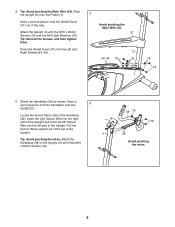
... with three M10 x 20mm Screws (79). 39 79 79 28 Avoid pinching the wires 8 Locate the Sensor Wires (28) in the Handlebar (39). Pull the Sensor Wires upward out of the top of the Upright. 2 Tip: Avoid pinching the wires. Have a second person hold the Shield Cover (37) out of the Upright. ...Tip: Start all the Screws, and then tighten them. Press the Shield Cover (37) into the left Sensor Wire into the Left and Right Shields (44, 45). 5 Avoid pinching the Main Wire (42) 37 2 44, 45 79 78 1 78 79 6. Orient the Handlebar (39) as shown. Tip: Avoid ...
... with three M10 x 20mm Screws (79). 39 79 79 28 Avoid pinching the wires 8 Locate the Sensor Wires (28) in the Handlebar (39). Pull the Sensor Wires upward out of the top of the Upright. 2 Tip: Avoid pinching the wires. Have a second person hold the Shield Cover (37) out of the Upright. ...Tip: Start all the Screws, and then tighten them. Press the Shield Cover (37) into the left Sensor Wire into the Left and Right Shields (44, 45). 5 Avoid pinching the Main Wire (42) 37 2 44, 45 79 78 1 78 79 6. Orient the Handlebar (39) as shown. Tip: Avoid ...
English Manual
Page 9
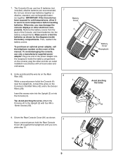
... the receptacle inside the battery compartments. IMPORTANT: If the Console has been exposed to cold temperatures, allow it to warm to the Sensor Wires (28). Make sure to the Upright (2) with all local codes and ordinances. 8. Plug one end of the power adapter into an...and rechargeable batter- Orient the Rear Console Cover (81) as shown by the diagrams inside the battery compartment on the Console to the Main Wire (42) and to room temperature before inserting batteries. To avoid damaging the console, use only a manufacturer-supplied power adapter. Remove the ...
... the receptacle inside the battery compartments. IMPORTANT: If the Console has been exposed to cold temperatures, allow it to warm to the Sensor Wires (28). Make sure to the Upright (2) with all local codes and ordinances. 8. Plug one end of the power adapter into an...and rechargeable batter- Orient the Rear Console Cover (81) as shown by the diagrams inside the battery compartment on the Console to the Main Wire (42) and to room temperature before inserting batteries. To avoid damaging the console, use only a manufacturer-supplied power adapter. Remove the ...
English Manual
Page 25
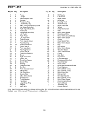
... Cover 22 2 Pivot Cover B 23 4 Pedal Arm Bushing 24 1 Crank 25 1 Right Crank Arm 26 2 Pedal Disc 27 1 Crank Arm Spacer 28 2 Sensor Wire 29 4 Bearing 30 2 Pedal Arm Cap 31 2 Bolt Set 32 1 Front Console Cover 33 4 M8 Washer 34 1 Left Crank Arm 35 2 Sensor... 52 1 Idler 53 20 M4 x 16mm Screw 54 1 Resistance Motor 55 1 M4 x 16mm Ground Screw 56 4 M8 x 15mm Screw 57 1 Clamp 58 1 Reed Switch/Wire 59 4 M8 x 10mm Screw 60 1 Key 61 1 M8 Locknut 62 1 M6 x 16mm Screw 63 2 Shoulder Screw 64 10 #10 x 13mm Screw 65 1 Pulley 66...
... Cover 22 2 Pivot Cover B 23 4 Pedal Arm Bushing 24 1 Crank 25 1 Right Crank Arm 26 2 Pedal Disc 27 1 Crank Arm Spacer 28 2 Sensor Wire 29 4 Bearing 30 2 Pedal Arm Cap 31 2 Bolt Set 32 1 Front Console Cover 33 4 M8 Washer 34 1 Left Crank Arm 35 2 Sensor... 52 1 Idler 53 20 M4 x 16mm Screw 54 1 Resistance Motor 55 1 M4 x 16mm Ground Screw 56 4 M8 x 15mm Screw 57 1 Clamp 58 1 Reed Switch/Wire 59 4 M8 x 10mm Screw 60 1 Key 61 1 M8 Locknut 62 1 M6 x 16mm Screw 63 2 Shoulder Screw 64 10 #10 x 13mm Screw 65 1 Pulley 66...

