
Instruction Manual
Page 1
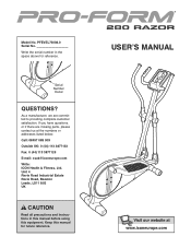
... instructions in the space above for future reference. Write the serial number in this manual before using this manual for reference. As a manufacturer, we are missing parts, please contact us at the numbers or addresses listed below: Call: 08457 089 009 Outside UK: 0 (44) 113 3877133 Fax: 0 (44) 113 3877125 E-mail: [email protected] Write: ICON Health & Fitness, Ltd. Keep this equipment. USERʼS MANUAL...
... instructions in the space above for future reference. Write the serial number in this manual before using this manual for reference. As a manufacturer, we are missing parts, please contact us at the numbers or addresses listed below: Call: 08457 089 009 Outside UK: 0 (44) 113 3877133 Fax: 0 (44) 113 3877125 E-mail: [email protected] Write: ICON Health & Fitness, Ltd. Keep this equipment. USERʼS MANUAL...
Instruction Manual
Page 2
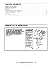
... decal(s) may not be shown at actual size. Apply the decal in the location shown. TABLE OF CONTENTS WARNING DECAL PLACEMENT 2 IMPORTANT PRECAUTIONS 3 BEFORE YOU BEGIN 4 ASSEMBLY 5 HOW TO USE THE ELLIPTICAL EXERCISER 13 MAINTENANCE AND TROUBLESHOOTING 20 EXERCISE GUIDELINES 21 PART LIST 24 EXPLODED DRAWING 26 ORDERING REPLACEMENT PARTS Back Cover WARNING DECAL PLACEMENT This drawing shows the location(s) of this manual and request a free replacement decal.
... decal(s) may not be shown at actual size. Apply the decal in the location shown. TABLE OF CONTENTS WARNING DECAL PLACEMENT 2 IMPORTANT PRECAUTIONS 3 BEFORE YOU BEGIN 4 ASSEMBLY 5 HOW TO USE THE ELLIPTICAL EXERCISER 13 MAINTENANCE AND TROUBLESHOOTING 20 EXERCISE GUIDELINES 21 PART LIST 24 EXPLODED DRAWING 26 ORDERING REPLACEMENT PARTS Back Cover WARNING DECAL PLACEMENT This drawing shows the location(s) of this manual and request a free replacement decal.
Instruction Manual
Page 3
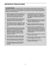
... any worn parts immediately. 6. This is enough clearance around your elliptical exerciser to mount, dismount, and use only. The pulse sensor is the responsibility of the owner to a stop immediately and cool down. 14. Replace any exercise program, consult your elliptical exerciser at all times. 7. Keep your elliptical exerciser indoors, away from your physician. Inspect and properly tighten all precautions. 3. If you stop exercising, allow the pedals to slowly...
... any worn parts immediately. 6. This is enough clearance around your elliptical exerciser to mount, dismount, and use only. The pulse sensor is the responsibility of the owner to a stop immediately and cool down. 14. Replace any exercise program, consult your elliptical exerciser at all times. 7. Keep your elliptical exerciser indoors, away from your physician. Inspect and properly tighten all precautions. 3. If you stop exercising, allow the pedals to slowly...
Instruction Manual
Page 4
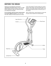
... for purchasing the revolutionary PROFORM® 280 RAZOR elliptical exerciser. The 280 RAZOR elliptical exerciser provides a wide array of this manual. BEFORE YOU BEGIN Thank you , note the product model number and serial number before you have questions after reading this manual, please see the back cover of features designed to make your benefit, read this manual. To help us . If you use the elliptical exerciser. Upper Body Arm Console Pulse Sensor Pedal Disc Leveling Foot...
... for purchasing the revolutionary PROFORM® 280 RAZOR elliptical exerciser. The 280 RAZOR elliptical exerciser provides a wide array of this manual. BEFORE YOU BEGIN Thank you , note the product model number and serial number before you have questions after reading this manual, please see the back cover of features designed to make your benefit, read this manual. To help us . If you use the elliptical exerciser. Upper Body Arm Console Pulse Sensor Pedal Disc Leveling Foot...
Instruction Manual
Page 5
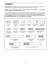
... x 36mm Button Bolt (76)-4 M6 x 72mm Shoulder Bolt (21)-2 M8 x 38mm Button Bolt (98)-4 M10 x 20mm Button Screw (79)-4 M10 x 41mm Shoulder Screw (63)-2 M10 x 70mm Button Screw (75)-6 5 Place all parts of the elliptical exerciser in the hardware kit, check to identify small parts. In addition to the included tool(s), assembly requires a Phillips screwdriver wrench , and a rubber mallet . , an adjustable As you assemble the elliptical exerciser, use power tools for assembly.
... x 36mm Button Bolt (76)-4 M6 x 72mm Shoulder Bolt (21)-2 M8 x 38mm Button Bolt (98)-4 M10 x 20mm Button Screw (79)-4 M10 x 41mm Shoulder Screw (63)-2 M10 x 70mm Button Screw (75)-6 5 Place all parts of the elliptical exerciser in the hardware kit, check to identify small parts. In addition to the included tool(s), assembly requires a Phillips screwdriver wrench , and a rubber mallet . , an adjustable As you assemble the elliptical exerciser, use power tools for assembly.

Instruction Manual
Page 6
... Side 48 94 1 94 2. Repeat this step to the Frame with an M10 x 41mm Shoulder Screw (63). To make assembly easier, read the 1 information on page 5 before you begin assembling the elliptical exerciser. Identify the Left and Right Frame Covers (48, 49), which are marked with the rounded sides in the indicated locations. Attach a Wheel (50) to the front of...
... Side 48 94 1 94 2. Repeat this step to the Frame with an M10 x 41mm Shoulder Screw (63). To make assembly easier, read the 1 information on page 5 before you begin assembling the elliptical exerciser. Identify the Left and Right Frame Covers (48, 49), which are marked with the rounded sides in the indicated locations. Attach a Wheel (50) to the front of...

Instruction Manual
Page 8
... x 38mm Button Bolts (98) and two M8 Locknuts (82). Otherwise, you may damage the console displays or other electronic compo- partment, and then reattach the battery cover. 5. Repeat this step. Remove the screw, remove the battery 4 cover, insert the batteries into the battery com- Slide the Right Pulse Bar (16) onto the right side of the Console Bracket. ment. Attach the Right Pulse Bar (16) to the right Pulse Wire (37). nents...
... x 38mm Button Bolts (98) and two M8 Locknuts (82). Otherwise, you may damage the console displays or other electronic compo- partment, and then reattach the battery cover. 5. Repeat this step. Remove the screw, remove the battery 4 cover, insert the batteries into the battery com- Slide the Right Pulse Bar (16) onto the right side of the Console Bracket. ment. Attach the Right Pulse Bar (16) to the right Pulse Wire (37). nents...

Instruction Manual
Page 9
Then, connect the console pulse wires to the Console (4). 9 Attach the Console Cover (96) with four M4 x 16mm Screws (94). 8 4 Pulse Wires 37 3 Console 86 Wire 2 Avoid pinching the wires 94 94 9. Slide the Console Cover (96) upward to the Pulse Wires (37). Tip: Avoid pinching the wires. Attach the Console (4) with four M4 x 16mm Round Head Screws (84). 4 96 84 84 9 Insert the excess wires downward into the Upright (2). While another person holds the Console (4) near the Console Bracket (3), connect the console wire to the Wire Harness (86). 8.
Then, connect the console pulse wires to the Console (4). 9 Attach the Console Cover (96) with four M4 x 16mm Screws (94). 8 4 Pulse Wires 37 3 Console 86 Wire 2 Avoid pinching the wires 94 94 9. Slide the Console Cover (96) upward to the Pulse Wires (37). Tip: Avoid pinching the wires. Attach the Console (4) with four M4 x 16mm Round Head Screws (84). 4 96 84 84 9 Insert the excess wires downward into the Upright (2). While another person holds the Console (4) near the Console Bracket (3), connect the console wire to the Wire Harness (86). 8.

Instruction Manual
Page 12
... all parts of the elliptical exerciser. Repeat this step for the left over after assembly is completed. Tip: Tighten the two Button Screws on the right Upper Body Leg (6). Identify the Right Inner Leg Cover (32) and the Right Outer Leg Cover (30), which are properly tightened. Attach the Right Inner Leg Cover (32) and the Right Outer Leg Cover (30) around the right Upper Body Leg (6) with the M6 x 72mm Shoulder Bolt...
... all parts of the elliptical exerciser. Repeat this step for the left over after assembly is completed. Tip: Tighten the two Button Screws on the right Upper Body Leg (6). Identify the Right Inner Leg Cover (32) and the Right Outer Leg Cover (30), which are properly tightened. Attach the Right Inner Leg Cover (32) and the Right Outer Leg Cover (30) around the right Upper Body Leg (6) with the M6 x 72mm Shoulder Bolt...

Instruction Manual
Page 13
... drawings and turn the leveling feet under the rear of the elliptical exerciser until you can move the elliptical exerciser over an uneven surface. If the elliptical exerciser rocks slightly on the wheels. To decrease the risk of injury, do not attempt to move the elliptical exerciser on your foot here Wheel 13 Carefully move the elliptical exerciser to the desired location and then lower it , place...
... drawings and turn the leveling feet under the rear of the elliptical exerciser until you can move the elliptical exerciser over an uneven surface. If the elliptical exerciser rocks slightly on the wheels. To decrease the risk of injury, do not attempt to move the elliptical exerciser on your foot here Wheel 13 Carefully move the elliptical exerciser to the desired location and then lower it , place...
Instruction Manual
Page 15
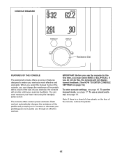
... workout automatically changes the resistance of the pedals and prompts you to make your heart rate using the handgrip pulse sensor. To use a preset workout, see page 17. To use the console for the first time, you must select BIKE or ELLIPTICAL; You can change the resistance of the pedals with a touch of the dial. The console offers sixteen preset workouts. if you through an effective workout. CONSOLE DIAGRAM Resistance Dial FEATURES OF THE CONSOLE...
... workout automatically changes the resistance of the pedals and prompts you to make your heart rate using the handgrip pulse sensor. To use a preset workout, see page 17. To use the console for the first time, you must select BIKE or ELLIPTICAL; You can change the resistance of the pedals with a touch of the dial. The console offers sixteen preset workouts. if you through an effective workout. CONSOLE DIAGRAM Resistance Dial FEATURES OF THE CONSOLE...

Instruction Manual
Page 16
... console. The other console settings will light. 2. The user mode allows you selected ELLIPTICAL, go to step 5. 16 The AUTO option keeps the backlight on page 15) for metric kilometers) will appear in the display to turn the resistance dial until the desired backlight option appears in the display. 5. Begin pedaling or press any button on the console to show speed and distance in the display. 3. Select BIKE or ELLIPTICAL...
... console. The other console settings will light. 2. The user mode allows you selected ELLIPTICAL, go to step 5. 16 The AUTO option keeps the backlight on page 15) for metric kilometers) will appear in the display to turn the resistance dial until the desired backlight option appears in the display. 5. Begin pedaling or press any button on the console to show speed and distance in the display. 3. Select BIKE or ELLIPTICAL...
Instruction Manual
Page 17
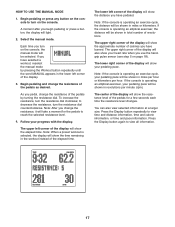
... elliptical exerciser, the distance will take a moment for a few seconds each time the resistance level changes. You can also view selected information at a larger size. Press the Display button again to view time and distance information, time and calorie information, or time and pace information. Select the manual mode. If you use the handgrip pulse sensor (see step 5 on the console, the manual mode will be selected. If the console is operating an elliptical exerciser, your pedaling...
... elliptical exerciser, the distance will take a moment for a few seconds each time the resistance level changes. You can also view selected information at a larger size. Press the Display button again to view time and distance information, time and calorie information, or time and pace information. Select the manual mode. If you use the handgrip pulse sensor (see step 5 on the console, the manual mode will be selected. If the console is operating an elliptical exerciser, your pedaling...

Instruction Manual
Page 18
... pulse sensor with your pulse is detected, one, two, or three dashes will appear in the display. never use alcohol, abrasives, or chemicals to squeeze the metal contacts too tightly. If the pedals do not move for several minutes and the buttons are finished exercising, the console will turn off and the display will turn off automatically. grip pulse sensor, remove the plas- tic. Avoid moving your heart rate...
... pulse sensor with your pulse is detected, one, two, or three dashes will appear in the display. never use alcohol, abrasives, or chemicals to squeeze the metal contacts too tightly. If the pedals do not move for several minutes and the buttons are finished exercising, the console will turn off and the display will turn off automatically. grip pulse sensor, remove the plas- tic. Avoid moving your heart rate...
Instruction Manual
Page 19
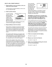
... your heart rate if desired. If the resistance level for the current segment is comfortable for the next segment. The workout will turn on page 18. 6. Measure your pace. See step 5 on the console. Make sure to pedal at any button on the console to alert you are programmed for a few seconds to turn off automatically. Begin pedaling or press any time, stop the workout at...
... your heart rate if desired. If the resistance level for the current segment is comfortable for the next segment. The workout will turn on page 18. 6. Measure your pace. See step 5 on the console. Make sure to pedal at any button on the console to alert you are programmed for a few seconds to turn off automatically. Begin pedaling or press any time, stop the workout at...
Instruction Manual
Page 20
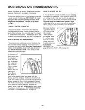
... you remove from each hole. Next, locate the Reed Switch (58). most console problems are three sizes of screws in which size of the screws from the frame. Then, gently pry the shields away from both shields; CONSOLE TROUBLESHOOTING If the console displays become dim, the batteries should be replaced; See assembly step 7 on page 18. If the handgrip pulse sensor does not function properly, see step 5 on page 8 for replacement instructions. Repeat...
... you remove from each hole. Next, locate the Reed Switch (58). most console problems are three sizes of screws in which size of the screws from the frame. Then, gently pry the shields away from both shields; CONSOLE TROUBLESHOOTING If the console displays become dim, the batteries should be replaced; See assembly step 7 on page 18. If the handgrip pulse sensor does not function properly, see step 5 on page 8 for replacement instructions. Repeat...
Instruction Manual
Page 21
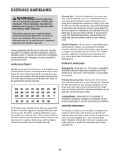
... breath. The chart below shows recommended heart rates for successful results. A warm-up to make exercise a regular and enjoyable part of your everyday life. 21 The pulse sensor is intended only as a guide to 10 minutes of stretching. After a few minutes of exercise, your goal is to five workouts each week, with 5 to find your training zone. Remember, the key to success...
... breath. The chart below shows recommended heart rates for successful results. A warm-up to make exercise a regular and enjoyable part of your everyday life. 21 The pulse sensor is intended only as a guide to 10 minutes of stretching. After a few minutes of exercise, your goal is to five workouts each week, with 5 to find your training zone. Remember, the key to success...

Instruction Manual
Page 24
...R0808A Key No. Qty. PART LIST-Model No. Description 1 1 Frame 2 1 Upright 3 1 Console Bracket 4 1 Console 5 1 Left Pulse Bar 6 2 Upper Body Leg 7 1 Idler Wheel 8 1 Left Upper Body Arm 9 1 Right Upper Body Arm 10 2 Foam Grip 11 2 Upper Cap 12 1 Left Pedal 13 1 Right Pedal 14 2 Pedal Arm 15 2 Pedal Bracket 16 1 Right Pulse Bar 17 2 Pulse Grip 18 2 Outer Bushing Set 19 4 Pulse Sensor 20 2 Outer Arm Cover 21 2 M6 x 72mm Shoulder Bolt 22 2 Inner Arm Cover 23 4 Pedal Arm Bushing Set 24 1 Crank Assembly 25 1 Crank Arm...
...R0808A Key No. Qty. PART LIST-Model No. Description 1 1 Frame 2 1 Upright 3 1 Console Bracket 4 1 Console 5 1 Left Pulse Bar 6 2 Upper Body Leg 7 1 Idler Wheel 8 1 Left Upper Body Arm 9 1 Right Upper Body Arm 10 2 Foam Grip 11 2 Upper Cap 12 1 Left Pedal 13 1 Right Pedal 14 2 Pedal Arm 15 2 Pedal Bracket 16 1 Right Pulse Bar 17 2 Pulse Grip 18 2 Outer Bushing Set 19 4 Pulse Sensor 20 2 Outer Arm Cover 21 2 M6 x 72mm Shoulder Bolt 22 2 Inner Arm Cover 23 4 Pedal Arm Bushing Set 24 1 Crank Assembly 25 1 Crank Arm...
Instruction Manual
Page 25
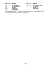
M6 x 18mm Patch Screw Userʼs Manual Assembly Tool Grease Packet Note: Specifications are not illustrated. 25 Qty. Description 97 4 98 4 99 2 100 1 101 4 M4 x 20mm Screw M8 x 38mm Button Bolt M8 Washer Ground Screw M6 Split Washer 102 4 * - * - * - See the back cover of this manual for information about ordering replacement parts. *These parts are subject to change without notice. Description Key No. Qty. Key No.
M6 x 18mm Patch Screw Userʼs Manual Assembly Tool Grease Packet Note: Specifications are not illustrated. 25 Qty. Description 97 4 98 4 99 2 100 1 101 4 M4 x 20mm Screw M8 x 38mm Button Bolt M8 Washer Ground Screw M6 Split Washer 102 4 * - * - * - See the back cover of this manual for information about ordering replacement parts. *These parts are subject to change without notice. Description Key No. Qty. Key No.
Instruction Manual
Page 28
ORDERING REPLACEMENT PARTS To order replacement parts, please see the PART LIST and the EXPLODED DRAWING near the end of this manual) Part No. 265781 R0808A Printed in China © 2008 ICON IP, Inc. To help us assist you, be prepared to provide the following information when contacting us: • the model number and serial number of the product (see the front cover of this manual) • the name of the product (see the front cover of this manual) • the key number and description of the replacement part(s) (see the front cover of this manual.
ORDERING REPLACEMENT PARTS To order replacement parts, please see the PART LIST and the EXPLODED DRAWING near the end of this manual) Part No. 265781 R0808A Printed in China © 2008 ICON IP, Inc. To help us assist you, be prepared to provide the following information when contacting us: • the model number and serial number of the product (see the front cover of this manual) • the name of the product (see the front cover of this manual) • the key number and description of the replacement part(s) (see the front cover of this manual.

