
English Manual
Page 2
... a free replacement decal. PROFORM is missing or illegible, see the front cover of ICON IP, Inc. iPad® is a trademark of the warning decal(s). TABLE OF CONTENTS WARNING DECAL PLACEMENT 2 IMPORTANT PRECAUTIONS 3 BEFORE YOU BEGIN 6 PART IDENTIFICATION CHART 7 ASSEMBLY 8 THE CHEST HEART RATE MONITOR 18 HOW TO USE THE ELLIPTICAL 19 MAINTENANCE AND...
... a free replacement decal. PROFORM is missing or illegible, see the front cover of ICON IP, Inc. iPad® is a trademark of the warning decal(s). TABLE OF CONTENTS WARNING DECAL PLACEMENT 2 IMPORTANT PRECAUTIONS 3 BEFORE YOU BEGIN 6 PART IDENTIFICATION CHART 7 ASSEMBLY 8 THE CHEST HEART RATE MONITOR 18 HOW TO USE THE ELLIPTICAL 19 MAINTENANCE AND...
English Manual
Page 7
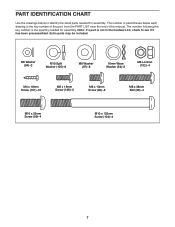
... part, from the PART LIST near the end of this manual. PART IDENTIFICATION CHART Use the drawings below each drawing is the quantity needed for assembly. The number in the hardware kit, check to identify the small parts needed for...
... part, from the PART LIST near the end of this manual. PART IDENTIFICATION CHART Use the drawings below each drawing is the quantity needed for assembly. The number in the hardware kit, check to identify the small parts needed for...
English Manual
Page 8
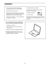
...you have Internet access, call CUSTOMER CARE (see the front cover of this product, call 1-800-445-2480. •• Assembly requires two persons. •• Place all assembly steps. •• Left parts are marked “"L”" or “"Left”" and right parts are marked “"R&#...148;" or “"Right.”" •• To identify small parts, see page 7. •• In addition to assemble this manual) and register your own set of the packing materials until you do not use power tools. 1. Do not dispose of wrenches. To avoid...
...you have Internet access, call CUSTOMER CARE (see the front cover of this product, call 1-800-445-2480. •• Assembly requires two persons. •• Place all assembly steps. •• Left parts are marked “"L”" or “"Left”" and right parts are marked “"R&#...148;" or “"Right.”" •• To identify small parts, see page 7. •• In addition to assemble this manual) and register your own set of the packing materials until you do not use power tools. 1. Do not dispose of wrenches. To avoid...
English Manual
Page 13
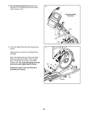
Orient the Right Pedal Arm (58) assembly as shown. Attach the Right Pedal Arm (58) to the Right Roller Arm (59) with four M4 x 10 16mm Screws (101). 7 Avoid pinching the wires 4 101 101 11. Tip: Avoid damaging the Small Axle Cover when tightening the Screw. Apply grease to the Upright (4) with an M8 x 13mm Screw (82), a Small Axle Cover (55), and an M8 Washer (97). Attach the Console (7) to the axle on the Right Pedal Arm (58). Tip: Avoid pinching the wires. 10. Repeat this step for the Left Pedal Arm assembly (not shown). 11 82 55 59 97 58 Grease 13
Orient the Right Pedal Arm (58) assembly as shown. Attach the Right Pedal Arm (58) to the Right Roller Arm (59) with four M4 x 10 16mm Screws (101). 7 Avoid pinching the wires 4 101 101 11. Tip: Avoid damaging the Small Axle Cover when tightening the Screw. Apply grease to the Upright (4) with an M8 x 13mm Screw (82), a Small Axle Cover (55), and an M8 Washer (97). Attach the Console (7) to the axle on the Right Pedal Arm (58). Tip: Avoid pinching the wires. 10. Repeat this step for the Left Pedal Arm assembly (not shown). 11 82 55 59 97 58 Grease 13
English Manual
Page 14
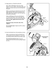
... (73, 74). 75 Avoid pinching the wires 4 73, 74 146 136 14 Then, tighten both parts. See assembly step 5. Orient the Shield Cover (75) assembly as shown. 13 While a second person holds the Shield Cover (75) assembly near the Upright (4), connect the Fan Extension Wire (146) to a Pedal Arm Axle (64). 12 Next... at the same time. Apply grease to the Fan Wire (136). Tip: Avoid pinching the wires. While a second person holds the front end of the elliptical.
... (73, 74). 75 Avoid pinching the wires 4 73, 74 146 136 14 Then, tighten both parts. See assembly step 5. Orient the Shield Cover (75) assembly as shown. 13 While a second person holds the Shield Cover (75) assembly near the Upright (4), connect the Fan Extension Wire (146) to a Pedal Arm Axle (64). 12 Next... at the same time. Apply grease to the Fan Wire (136). Tip: Avoid pinching the wires. While a second person holds the front end of the elliptical.
English Manual
Page 35
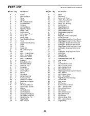
... Axle Cover Roller Arm Bushing Arm Bearing Right Pedal Arm Right Roller Arm Right Upper Body Leg Right Upper Body Arm Left Grip Right Sensor Assembly/Wire Pedal Arm Axle Right Upper Body Arm Front Cover Right Upper Body Arm Rear Cover Left Upper Body Arm Front Cover Left Upper Body...
... Axle Cover Roller Arm Bushing Arm Bearing Right Pedal Arm Right Roller Arm Right Upper Body Leg Right Upper Body Arm Left Grip Right Sensor Assembly/Wire Pedal Arm Axle Right Upper Body Arm Front Cover Right Upper Body Arm Rear Cover Left Upper Body Arm Front Cover Left Upper Body...
English Manual
Page 36
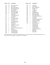
... Right Pedal Plate M3 x 8mm Screw M6 x 43mm Screw Chest Heart Rate Monitor Chest Strap Left Pedal Left Sensor Assembly/Wire Right Pedal Handle Fan Extension Wire iPad Holder M6 x 16mm Screw Assembly Tool Grease Packet User’'s Manual Lift Motor Wire A Lift Motor Wire B Resistance Motor Wire Blue Wire Green Wire...
... Right Pedal Plate M3 x 8mm Screw M6 x 43mm Screw Chest Heart Rate Monitor Chest Strap Left Pedal Left Sensor Assembly/Wire Right Pedal Handle Fan Extension Wire iPad Holder M6 x 16mm Screw Assembly Tool Grease Packet User’'s Manual Lift Motor Wire A Lift Motor Wire B Resistance Motor Wire Blue Wire Green Wire...


