
Service Manual
Page 2
... the back or bottom are unable to insert the plug into the outlet, contact your electrician to replace your dealer or local power company. (9) This product is a safety feature, if you are provided for cleaning. (5) Do not use liquid cleaners or aerosol cleaners; When... will often require extensive work by a qualified technician to restore the product to normal operation. Do not ignore the purpose of power source indicated on the power cord. Important Service and Safety Information Prior to using this service manual, please ensure that you have carefully followed all the procedures...
... the back or bottom are unable to insert the plug into the outlet, contact your electrician to replace your dealer or local power company. (9) This product is a safety feature, if you are provided for cleaning. (5) Do not use liquid cleaners or aerosol cleaners; When... will often require extensive work by a qualified technician to restore the product to normal operation. Do not ignore the purpose of power source indicated on the power cord. Important Service and Safety Information Prior to using this service manual, please ensure that you have carefully followed all the procedures...
Service Manual
Page 3
Never modify any components. Before servicing the TV, follow these service guidelines: ELECTRIC SHOCK HAZARD Always disconnect AC power before touching any circuit! Look at the markings on your workbench or other grounded connection. • Touch a bare metal surface on board...available at this television use lead-free solder that matches the symbol on the outside of antistatic bags because only the inside an LCD or plasma TV are meant to static electricity. PRECAUTIONS FOR USING LEAD-FREE SOLDER Components within the television to determine the correct solder type and ...
Never modify any components. Before servicing the TV, follow these service guidelines: ELECTRIC SHOCK HAZARD Always disconnect AC power before touching any circuit! Look at the markings on your workbench or other grounded connection. • Touch a bare metal surface on board...available at this television use lead-free solder that matches the symbol on the outside of antistatic bags because only the inside an LCD or plasma TV are meant to static electricity. PRECAUTIONS FOR USING LEAD-FREE SOLDER Components within the television to determine the correct solder type and ...

Service Manual
Page 4
... soldering bit after every use. (2) Keep the soldering bit in the television. When the tip of solder. Do not leave the bit powered on for their specific safety characteristics within LCD or plasma televisions are chosen for extended periods. (1) Always use a dedicated soldering bit for higher voltage or wattage can be identical...
... soldering bit after every use. (2) Keep the soldering bit in the television. When the tip of solder. Do not leave the bit powered on for their specific safety characteristics within LCD or plasma televisions are chosen for extended periods. (1) Always use a dedicated soldering bit for higher voltage or wattage can be identical...
Service Manual
Page 11
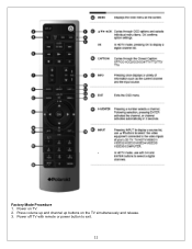
Factory Mode Procedure 1. Power on the TV simultaneously and release. 3. Power off TV with remote or power button to exit. 11 Press volume up and channel up buttons on TV. 2.
Factory Mode Procedure 1. Power on the TV simultaneously and release. 3. Power off TV with remote or power button to exit. 11 Press volume up and channel up buttons on TV. 2.
Service Manual
Page 14
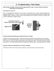
.... Troubleshooting / Flow Charts Note: Reseat all passwords. The factory preset password is equipped with a safety fuse. In the event you keep your TV has no power, check the fuse by AC plug, perform a clear or reset in -Picture will not work using Component 1 and Component 2 as the input...4A 250V - 5x20mm Time Lag Fuse (Slow Blow) to protect your Parental Controls (V-Chip)? Having trouble with setting your TV. In the event of an electrical storm or power outage the safety fuse is 8202. The master password overrides all cables, check fuse by prying the cover off, following...
.... Troubleshooting / Flow Charts Note: Reseat all passwords. The factory preset password is equipped with a safety fuse. In the event you keep your TV has no power, check the fuse by AC plug, perform a clear or reset in -Picture will not work using Component 1 and Component 2 as the input...4A 250V - 5x20mm Time Lag Fuse (Slow Blow) to protect your Parental Controls (V-Chip)? Having trouble with setting your TV. In the event of an electrical storm or power outage the safety fuse is 8202. The master password overrides all cables, check fuse by prying the cover off, following...

Service Manual
Page 20
...vent holes in the section, Before Returning This Product to the User, on the outside of antistatic bags because only the inside an LCD or plasma TV are sensitive to the end user, you might remove. • When removing components that the chassis will not cause electric shock. ...Never insert any part the TV, make sure the power is OFF, and the power cord is large enough to hold components you must follow these guidelines: • Avoid static-causing surfaces such as carpeted floors...
...vent holes in the section, Before Returning This Product to the User, on the outside of antistatic bags because only the inside an LCD or plasma TV are sensitive to the end user, you might remove. • When removing components that the chassis will not cause electric shock. ...Never insert any part the TV, make sure the power is OFF, and the power cord is large enough to hold components you must follow these guidelines: • Avoid static-causing surfaces such as carpeted floors...
Service Manual
Page 21
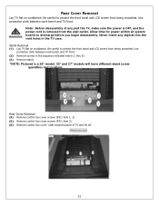
... Remove stand. *NOTE: Pictured is removed from the wall outlet. Stand Removal (1) Lay TV flat on workbench. Allow time for power within all system boards to protect the front bezel and LCD screen from being scratched. Be careful to discharge before you begin disassembly. Use protective cloth... control box cover- Use protective cloth between work bench and TV front. (2) Remove screws in the TV case. Never insert any part the TV, make sure the power is OFF, and the power cord is a 26" model. 32" and 37" models will have different stand screw quantities and locations.
... Remove stand. *NOTE: Pictured is removed from the wall outlet. Stand Removal (1) Lay TV flat on workbench. Allow time for power within all system boards to protect the front bezel and LCD screen from being scratched. Be careful to discharge before you begin disassembly. Use protective cloth... control box cover- Use protective cloth between work bench and TV front. (2) Remove screws in the TV case. Never insert any part the TV, make sure the power is OFF, and the power cord is a 26" model. 32" and 37" models will have different stand screw quantities and locations.
Service Manual
Page 22
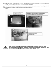
... page 19. Release control box from the A/V connector side (PIC1). This procedure ensures that are connected so be careful. Disconnect LVDS cable connector from LCD panel (PIC2). (9) Disconnect the LCD Panel power cord from bottom side of control box (PIC3). There are cables underneath that the chassis will not cause electric shock. 22
... page 19. Release control box from the A/V connector side (PIC1). This procedure ensures that are connected so be careful. Disconnect LVDS cable connector from LCD panel (PIC2). (9) Disconnect the LCD Panel power cord from bottom side of control box (PIC3). There are cables underneath that the chassis will not cause electric shock. 22
Service Manual
Page 23
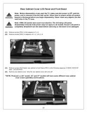
...completely detached from the wall outlet. Rear Cabinet Cover LCD Panel and Front Bezel Note: Before disassembly of any objects into the vent holes in the TV case. Never insert any part the TV, make sure the power is OFF, and the power cord is removed from the bezel before removing so...to front frame (PIC1) in production. Note: OEM LCD panels were used in the following LCD panel disassembly/removal instructions may not apply to all system boards to discharge before you begin disassembly. Ensure LCD panel is a 26" model. 32" and 37" models will have some different rear cabinet cover screw...
...completely detached from the wall outlet. Rear Cabinet Cover LCD Panel and Front Bezel Note: Before disassembly of any objects into the vent holes in the TV case. Never insert any part the TV, make sure the power is OFF, and the power cord is removed from the bezel before removing so...to front frame (PIC1) in production. Note: OEM LCD panels were used in the following LCD panel disassembly/removal instructions may not apply to all system boards to discharge before you begin disassembly. Ensure LCD panel is a 26" model. 32" and 37" models will have some different rear cabinet cover screw...

Service Manual
Page 29
...A/V board and replace (PIC2). (4) Push locking tabs in to secure replaced A/V board. Do the same for power within all system boards to discharge before you must follow the steps outlined in the TV case. (1) Disassemble control box cover and rear cabinet cover and remove A/V assembly. (2) Using a small pair ...wire cutters grip the side-locking tab and pivot back towards the A/V cable connector (PIC1). Never insert any part the TV, make sure the power is OFF, and the power cord is removed from the wall outlet. This procedure ensures that the chassis will not cause electric shock. 29 A/V ...
...A/V board and replace (PIC2). (4) Push locking tabs in to secure replaced A/V board. Do the same for power within all system boards to discharge before you must follow the steps outlined in the TV case. (1) Disassemble control box cover and rear cabinet cover and remove A/V assembly. (2) Using a small pair ...wire cutters grip the side-locking tab and pivot back towards the A/V cable connector (PIC1). Never insert any part the TV, make sure the power is OFF, and the power cord is removed from the wall outlet. This procedure ensures that the chassis will not cause electric shock. 29 A/V ...
Service Manual
Page 30
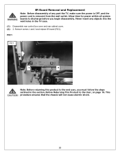
Never insert any part the TV, make sure the power is OFF, and the power cord is removed from the wall outlet. This procedure ensures that the chassis will not cause electric shock. 30 Allow time for power within all system boards to the User, on page 19. Remove screws 1 and 2 and ...replace IR board (PIC1). PIC1 PIC1 1 2 Note: Before returning this product to the end user, you must follow the steps outlined in the TV case. (1) Disassemble rear control box...
Never insert any part the TV, make sure the power is OFF, and the power cord is removed from the wall outlet. This procedure ensures that the chassis will not cause electric shock. 30 Allow time for power within all system boards to the User, on page 19. Remove screws 1 and 2 and ...replace IR board (PIC1). PIC1 PIC1 1 2 Note: Before returning this product to the end user, you must follow the steps outlined in the TV case. (1) Disassemble rear control box...

Service Manual
Page 31
Never insert any part the TV, make sure the power is OFF, and the power cord is attached with glue. Use alcohol to soften the glue and remove the control button board (PIC1). (3) Replace control button board and use glue ... objects into the vent holes in the section, Before Returning This Product to front bezel. Allow time for power within all system boards to discharge before you must follow the steps outlined in the TV case. (1) Disassemble control box cover and rear cabinet cover. (2) The control button board is removed from the...
Never insert any part the TV, make sure the power is OFF, and the power cord is attached with glue. Use alcohol to soften the glue and remove the control button board (PIC1). (3) Replace control button board and use glue ... objects into the vent holes in the section, Before Returning This Product to front bezel. Allow time for power within all system boards to discharge before you must follow the steps outlined in the TV case. (1) Disassemble control box cover and rear cabinet cover. (2) The control button board is removed from the...
Service Manual
Page 38
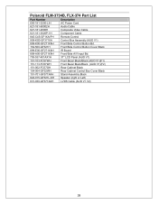
Polaroid FLM-3734B, FLX-374 Part List Part Number Description 600-181-3200-LIH AC Power Cord 621-181-60002H Audio Cable 621-181-2000H Composite Video Cable 621-181-3020P-1H Component Cable 845-C45-GF1XA-PH Remote Control 909-... Bd. 154-500-GF321H Front/Side Control Button Cover Black 899-E00-GF271XAH IR Board 899-A00-GF271XAH Front/Side A/V Input Bd. 705-537-401AX1H 37" LCD Panel (AUO V1) 151-103-FC57WH Front Bezel Black/Black (AUO V1)(F1) 151-113-FC57WH Front Bezel Black/Black (AUO V1)(F2) 151-002...
Polaroid FLM-3734B, FLX-374 Part List Part Number Description 600-181-3200-LIH AC Power Cord 621-181-60002H Audio Cable 621-181-2000H Composite Video Cable 621-181-3020P-1H Component Cable 845-C45-GF1XA-PH Remote Control 909-... Bd. 154-500-GF321H Front/Side Control Button Cover Black 899-E00-GF271XAH IR Board 899-A00-GF271XAH Front/Side A/V Input Bd. 705-537-401AX1H 37" LCD Panel (AUO V1) 151-103-FC57WH Front Bezel Black/Black (AUO V1)(F1) 151-113-FC57WH Front Bezel Black/Black (AUO V1)(F2) 151-002...

Service Manual
Page 43
... 0+ 8. Clock + 11. Red Video 2. Green Ground 8. GND 12. TMDS Data 24. TMDS Data 1+ 5. TMDS Data 0 shield 9. Clock 13. DDC DATA 17. CEC/GND 18. +5V Power 19. GND 5. Mini DIN CNC 4 Pins (SCN570S3NS00000) for DDC 6. TMDS Data 2+ 2. TMDS Data 010. NC 15. Vdd from PC 10. TMDS Data 1 shield 6. TMDS Data...
... 0+ 8. Clock + 11. Red Video 2. Green Ground 8. GND 12. TMDS Data 24. TMDS Data 1+ 5. TMDS Data 0 shield 9. Clock 13. DDC DATA 17. CEC/GND 18. +5V Power 19. GND 5. Mini DIN CNC 4 Pins (SCN570S3NS00000) for DDC 6. TMDS Data 2+ 2. TMDS Data 010. NC 15. Vdd from PC 10. TMDS Data 1 shield 6. TMDS Data...

Service Manual
Page 46
Signal Connector Pin Assignment Pin Assignment 1. Horizontal Sync. 9. Not Connected 14. Ground 15. Power Source Sound Output AC100 - 240 V, 60/50 Hz 10W X2, 8 Ohm. Vertical Sync. 10. Sync. Red Ground 11. Green Gro und 12. Self Test Pin Assignment Pin Assignment 6. Ground 7. Red 2. Blue Ground 13. SDA 8. Green 3. SCL 46 Ground 5. Blue 4.
Signal Connector Pin Assignment Pin Assignment 1. Horizontal Sync. 9. Not Connected 14. Ground 15. Power Source Sound Output AC100 - 240 V, 60/50 Hz 10W X2, 8 Ohm. Vertical Sync. 10. Sync. Red Ground 11. Green Gro und 12. Self Test Pin Assignment Pin Assignment 6. Ground 7. Red 2. Blue Ground 13. SDA 8. Green 3. SCL 46 Ground 5. Blue 4.
Service Manual
Page 48
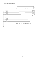
...: 886-2-2232-4613 Title KEYPAD PCB Size Document Number Rev A GF371-XU A Date: Friday , September 30, 2005 Sheet 1 of 1 48 Front/Side Control Buttons SW1 POWER-ON SW2 SOURCE SW3 MENU SW4 CH-UP SW5 CH-DOWN SW6 VOL-UP SW7 VOL-DOWN VCC R1 4.7K R2 4.7K R3 4.7K R4... 4.7K R5 4.7K R6 4.7K R7 4.7K C1 0.1uF J1 VCC POWER-ON 1 SOERCE 2 MENU 3 CH-UP 4 CH-DOWN 5 VOL-UP 6 VOL-DOWN 7 GND 8 9 CON9 Hous 9P-1.0 ZD1 5.6V ZD2 5.6V ZD3 5.6V ZD4 5.6V ZD5 5.6V...
...: 886-2-2232-4613 Title KEYPAD PCB Size Document Number Rev A GF371-XU A Date: Friday , September 30, 2005 Sheet 1 of 1 48 Front/Side Control Buttons SW1 POWER-ON SW2 SOURCE SW3 MENU SW4 CH-UP SW5 CH-DOWN SW6 VOL-UP SW7 VOL-DOWN VCC R1 4.7K R2 4.7K R3 4.7K R4... 4.7K R5 4.7K R6 4.7K R7 4.7K C1 0.1uF J1 VCC POWER-ON 1 SOERCE 2 MENU 3 CH-UP 4 CH-DOWN 5 VOL-UP 6 VOL-DOWN 7 GND 8 9 CON9 Hous 9P-1.0 ZD1 5.6V ZD2 5.6V ZD3 5.6V ZD4 5.6V ZD5 5.6V...
Service Manual
Page 50
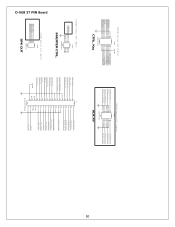
... 9 LED_G 7 IR-OUT 5 LTDC_INT 3 LTDC_DATA 1 16 SW7-VOL-DOWN 14 SW5-CH-DOWN 12 SW3-MENU 10 SW1-POWER 8 LED_O 6 LTDC_ADDR 4 LTDC_CLK 2 200PHD-16LT CTRL. Tel: 886-2-2231-6789 Fax: 886-2-2232-4613 Title CON JUNCT ... 2X7 (14pin) CON2 PHONE_A_D_O 13 14 11 12 FRONT_A_L_IN 9 10 7 8 FRONT_COMPOSITE 5 6 3 4 FRONT_S_CHROMA 1 2 PHONE_A_L_O PHONE_A_R_O FRONT_A_R_IN FRONT_S_LUMA 200PHD-14LT AUX AV D-SUB 37 PIN Board 5 0 200PHD Series 2X4 (8pin) CON3 VBLON ADJ_INV 7 8 5 6 3 4 1 2 200PHD-8LT INVERTER CTRL. 250XH Series 1X4 (4pin) CON4 SPK_L_OUT-...
... 9 LED_G 7 IR-OUT 5 LTDC_INT 3 LTDC_DATA 1 16 SW7-VOL-DOWN 14 SW5-CH-DOWN 12 SW3-MENU 10 SW1-POWER 8 LED_O 6 LTDC_ADDR 4 LTDC_CLK 2 200PHD-16LT CTRL. Tel: 886-2-2231-6789 Fax: 886-2-2232-4613 Title CON JUNCT ... 2X7 (14pin) CON2 PHONE_A_D_O 13 14 11 12 FRONT_A_L_IN 9 10 7 8 FRONT_COMPOSITE 5 6 3 4 FRONT_S_CHROMA 1 2 PHONE_A_L_O PHONE_A_R_O FRONT_A_R_IN FRONT_S_LUMA 200PHD-14LT AUX AV D-SUB 37 PIN Board 5 0 200PHD Series 2X4 (8pin) CON3 VBLON ADJ_INV 7 8 5 6 3 4 1 2 200PHD-8LT INVERTER CTRL. 250XH Series 1X4 (4pin) CON4 SPK_L_OUT-...


