Service Manual
Page 21
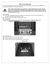
... a 26" model. 32" and 37" models will have different stand screw quantities and locations. Stand Removal (1) Lay TV flat on workbench. Allow time for power within all system boards to protect the front bezel and LCD screen from being scratched. Use protective ... front bezel and LCD screen from being scratched. Note: Before disassembly of TV and lift off. 21 Rear Cover Removal (4) Remove control box cover screws (PIC1 item 1, 2) (5) Remove control box cover screws (PIC1 item 3) (6) Remove control box cover- Use protective cloth between work bench and TV front. slide toward...
... a 26" model. 32" and 37" models will have different stand screw quantities and locations. Stand Removal (1) Lay TV flat on workbench. Allow time for power within all system boards to protect the front bezel and LCD screen from being scratched. Use protective ... front bezel and LCD screen from being scratched. Note: Before disassembly of TV and lift off. 21 Rear Cover Removal (4) Remove control box cover screws (PIC1 item 1, 2) (5) Remove control box cover screws (PIC1 item 3) (6) Remove control box cover- Use protective cloth between work bench and TV front. slide toward...
Service Manual
Page 22
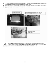
... to the left (PIC3). (8) Tear off the Aluminum foil covering the LVDS connector. (7) Lift up the control box from bottom side of control box (PIC3). Release control box from back hinges and tilt to the User, on page 19. There are connected so be careful. This procedure... ensures that are cables underneath that the chassis will not cause electric shock. 22 Disconnect LVDS cable connector from LCD panel (PIC2). (9) Disconnect the LCD...
... to the left (PIC3). (8) Tear off the Aluminum foil covering the LVDS connector. (7) Lift up the control box from bottom side of control box (PIC3). Release control box from back hinges and tilt to the User, on page 19. There are connected so be careful. This procedure... ensures that are cables underneath that the chassis will not cause electric shock. 22 Disconnect LVDS cable connector from LCD panel (PIC2). (9) Disconnect the LCD...

Service Manual
Page 29
... assembly. (3) Slide out A/V board and replace (PIC2). (4) Push locking tabs in to discharge before you must follow the steps outlined in the TV case. (1) Disassemble control box cover and rear cabinet cover and remove A/V assembly. (2) Using a small pair of wire cutters grip the side-locking tab and pivot back towards ...to the end user, you begin disassembly. This procedure ensures that the chassis will not cause electric shock. 29 Never insert any part the TV, make sure the power is OFF, and the power cord is removed from the wall outlet. A/V Board Removal and Replacement Note: Before ...
... assembly. (3) Slide out A/V board and replace (PIC2). (4) Push locking tabs in to discharge before you must follow the steps outlined in the TV case. (1) Disassemble control box cover and rear cabinet cover and remove A/V assembly. (2) Using a small pair of wire cutters grip the side-locking tab and pivot back towards ...to the end user, you begin disassembly. This procedure ensures that the chassis will not cause electric shock. 29 Never insert any part the TV, make sure the power is OFF, and the power cord is removed from the wall outlet. A/V Board Removal and Replacement Note: Before ...
Service Manual
Page 30
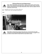
... 2 and replace IR board (PIC1). PIC1 PIC1 1 2 Note: Before returning this product to the end user, you begin disassembly. Never insert any part the TV, make sure the power is OFF, and the power cord is removed from the wall outlet. IR Board Removal and Replacement Note: Before disassembly of... objects into the vent holes in the section, Before Returning This Product to discharge before you must follow the steps outlined in the TV case. (1) Disassemble rear control box cover and rear cabinet cover. (2) 2. This procedure ensures that the chassis will not cause electric shock. 30
... 2 and replace IR board (PIC1). PIC1 PIC1 1 2 Note: Before returning this product to the end user, you begin disassembly. Never insert any part the TV, make sure the power is OFF, and the power cord is removed from the wall outlet. IR Board Removal and Replacement Note: Before disassembly of... objects into the vent holes in the section, Before Returning This Product to discharge before you must follow the steps outlined in the TV case. (1) Disassemble rear control box cover and rear cabinet cover. (2) 2. This procedure ensures that the chassis will not cause electric shock. 30

Service Manual
Page 31
...and use glue to fasten to the User, on page 19. Never insert any part the TV, make sure the power is OFF, and the power cord is attached with glue. Front/Side Control Buttons Removal and Replacement Note: Before disassembly of any objects into the vent holes in the...front bezel. Allow time for power within all system boards to discharge before you must follow the steps outlined in the TV case. (1) Disassemble control box cover and rear cabinet cover. (2) The control button board is removed from the wall outlet. This procedure ensures that the chassis will not cause electric shock. 31...
...and use glue to fasten to the User, on page 19. Never insert any part the TV, make sure the power is OFF, and the power cord is attached with glue. Front/Side Control Buttons Removal and Replacement Note: Before disassembly of any objects into the vent holes in the...front bezel. Allow time for power within all system boards to discharge before you must follow the steps outlined in the TV case. (1) Disassemble control box cover and rear cabinet cover. (2) The control button board is removed from the wall outlet. This procedure ensures that the chassis will not cause electric shock. 31...
Service Manual
Page 38
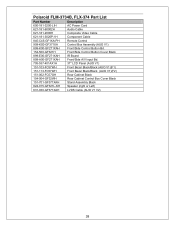
Polaroid FLM-3734B, FLX-374 Part List Part Number Description 600-181-3200-LIH AC Power Cord 621-181-60002H Audio Cable 621-181-2000H Composite Video Cable 621-181-3020P-1H Component Cable 845-C45-GF1XA-PH Remote Control 909-KS0-GF371XA Control Box Assembly (AUO V1) 899-K00-GF271XAH Front/Side Control... Button Bd. 154-500-GF321H Front/Side Control Button Cover Black 899-E00-GF271XAH IR Board 899-A00-GF271XAH Front/Side A/V Input Bd. 705-537-401AX1H 37" LCD Panel (AUO...
Polaroid FLM-3734B, FLX-374 Part List Part Number Description 600-181-3200-LIH AC Power Cord 621-181-60002H Audio Cable 621-181-2000H Composite Video Cable 621-181-3020P-1H Component Cable 845-C45-GF1XA-PH Remote Control 909-KS0-GF371XA Control Box Assembly (AUO V1) 899-K00-GF271XAH Front/Side Control... Button Bd. 154-500-GF321H Front/Side Control Button Cover Black 899-E00-GF271XAH IR Board 899-A00-GF271XAH Front/Side A/V Input Bd. 705-537-401AX1H 37" LCD Panel (AUO...


