Operation Manual
Page 2
......6 Remote Control...8 Connections...10 Cautions Before Connecting ...10 To connect AV1/S-VIDEO input terminals ...10 To connect AV2 input terminals ...11 To connect Component input terminals ...12 To connect DVI input ...13 To connect D-Sub input...14 To connect AV output terminals ...15 Turning the Unit On and Off...16 Turning the Unit On and Off ...16 Viewing the Menus and Displays ...16 Basic Operations ...17 Adjusting the Volume...17 Selecting Input Source Signal ...18 Selecting a Menu Language...18 Setting Picture...
......6 Remote Control...8 Connections...10 Cautions Before Connecting ...10 To connect AV1/S-VIDEO input terminals ...10 To connect AV2 input terminals ...11 To connect Component input terminals ...12 To connect DVI input ...13 To connect D-Sub input...14 To connect AV output terminals ...15 Turning the Unit On and Off...16 Turning the Unit On and Off ...16 Viewing the Menus and Displays ...16 Basic Operations ...17 Adjusting the Volume...17 Selecting Input Source Signal ...18 Selecting a Menu Language...18 Setting Picture...

Operation Manual
Page 3
... Viewing Picture-by-Picture ...28 Using Hotkeys ...29 Setting Sleep Timer...29 To pause Picture...29 Viewing Closed Captions...30 Turning Closed Caption On or Off...30 Setting Closed Caption...30 Setting CC When Mute...30 Adjusting Child Lock Settings ...31 Child Lock...31 Turning Child Lock On or Off...33 Changing the Password ...33 Adjusting the Movie Rating...33 Adjusting the TV Rating...33 Adjusting Canadian English Rating...34 Adjusting Canadian French Rating...34 Troubleshooting ...35 Care and Maintenance ...36 Specification ...37 Programming the Universal Remote Control...
... Viewing Picture-by-Picture ...28 Using Hotkeys ...29 Setting Sleep Timer...29 To pause Picture...29 Viewing Closed Captions...30 Turning Closed Caption On or Off...30 Setting Closed Caption...30 Setting CC When Mute...30 Adjusting Child Lock Settings ...31 Child Lock...31 Turning Child Lock On or Off...33 Changing the Password ...33 Adjusting the Movie Rating...33 Adjusting the TV Rating...33 Adjusting Canadian English Rating...34 Adjusting Canadian French Rating...34 Troubleshooting ...35 Care and Maintenance ...36 Specification ...37 Programming the Universal Remote Control...

Operation Manual
Page 4
...local authorities or the Electronic Industries Alliance: www.eia.org FCC STATEMENT FCC Notice LCD Monitor: A CLASS B digital device This equipment has been tested and found to comply with the instruction manual, may cause harmful interference to radio communications. In a domestic environment this product may...of the FCC rules, any servicing other than that may be required to persons. This equipment generates, uses, and can radiate radio frequency energy and, if not installed and used in a commercial environment. FCC CAUTION: Pursuant to 47CFR, Part 15.21 of electric shock to...
...local authorities or the Electronic Industries Alliance: www.eia.org FCC STATEMENT FCC Notice LCD Monitor: A CLASS B digital device This equipment has been tested and found to comply with the instruction manual, may cause harmful interference to radio communications. In a domestic environment this product may...of the FCC rules, any servicing other than that may be required to persons. This equipment generates, uses, and can radiate radio frequency energy and, if not installed and used in a commercial environment. FCC CAUTION: Pursuant to 47CFR, Part 15.21 of electric shock to...

Operation Manual
Page 6
... into the product. Stand---Use only with the cart, stand, tripod, bracket, or table specified by the manufacturer, or those described in performance. Servicing is required when the apparatus has been damaged in proper operating condition. 21.Wall or ceiling mounting---When mounting the product on an unstable base can cause damage, which often requires extensive adjustment work , request the service technician to perform...
... into the product. Stand---Use only with the cart, stand, tripod, bracket, or table specified by the manufacturer, or those described in performance. Servicing is required when the apparatus has been damaged in proper operating condition. 21.Wall or ceiling mounting---When mounting the product on an unstable base can cause damage, which often requires extensive adjustment work , request the service technician to perform...

Operation Manual
Page 8
Preparations Using the Remote Control
Preparations Using the Remote Control
Operation Manual
Page 10
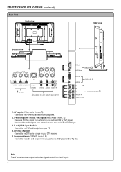
...or DVD player. 3. DVI input /Audio in Connect to the DVI/audio outputs on your DTV receiver. 5. Note: The AV output terminals output audio/video signal inputted from external sources such as VCR or DVD player. AV outputs (Video, Audio L/mono, R) Connect to the VCR input jacks to the audio and component output jacks of Controls (continued) Main Unit Back view Side view Bottom view AV OUT VIDEO L AUDIO R S-VIDEO VIDEO L AUDIO R AV2 IN VIDEO L AUDIO R AV1 IN AV OUT VIDEO L AUDIO R VIDEO AUDIO L AUDIO R S-VIDEO S-VIDEO VIDEO VIDEO VIDEO L AUDIO R AV2 IN L AUDIO R AV1...
...or DVD player. 3. DVI input /Audio in Connect to the DVI/audio outputs on your DTV receiver. 5. Note: The AV output terminals output audio/video signal inputted from external sources such as VCR or DVD player. AV outputs (Video, Audio L/mono, R) Connect to the VCR input jacks to the audio and component output jacks of Controls (continued) Main Unit Back view Side view Bottom view AV OUT VIDEO L AUDIO R S-VIDEO VIDEO L AUDIO R AV2 IN VIDEO L AUDIO R AV1 IN AV OUT VIDEO L AUDIO R VIDEO AUDIO L AUDIO R S-VIDEO S-VIDEO VIDEO VIDEO VIDEO L AUDIO R AV2 IN L AUDIO R AV1...

Operation Manual
Page 12
... CCD channel 16. PIP INPUT 12 18 To select signal input source for TVPC or PIP frame 13 19 14 20 20. SRS technology is displaying a PC screen. * The SRS symbol are trademark of Controls (continued) Remote Control 10. ASPECT To select screen aspect ratio 11. PICTURE MODE Picture mode select 18. SLEEP To set Sleep timer 17. TV/PC To activate TVPC function Note: The TVPC function means you may view a video program from...
... CCD channel 16. PIP INPUT 12 18 To select signal input source for TVPC or PIP frame 13 19 14 20 20. SRS technology is displaying a PC screen. * The SRS symbol are trademark of Controls (continued) Remote Control 10. ASPECT To select screen aspect ratio 11. PICTURE MODE Picture mode select 18. SLEEP To set Sleep timer 17. TV/PC To activate TVPC function Note: The TVPC function means you may view a video program from...

Operation Manual
Page 13
... the operating manual of the external equipment may be different depending on your source supports it. How to avoid any connections. To play VCR 1. To use the S-video terminal if your model. Turn on your VCR , insert a videotape and press the Play button. Turn on the panel to connect: Connect the Audio/Video cables between the Audio (L/R)/Video jacks on the remote control. 2. Loose connectors can use Video terminal, you should disconnect S-video. Rw Y R AUDIOOUT L VIDEO OUT S-VIDEO OUT Input...
... the operating manual of the external equipment may be different depending on your source supports it. How to avoid any connections. To play VCR 1. To use the S-video terminal if your model. Turn on your VCR , insert a videotape and press the Play button. Turn on the panel to connect: Connect the Audio/Video cables between the Audio (L/R)/Video jacks on the remote control. 2. Loose connectors can use Video terminal, you should disconnect S-video. Rw Y R AUDIOOUT L VIDEO OUT S-VIDEO OUT Input...

Operation Manual
Page 14
... Audio (L/R)/Video jacks on your camcorder and set it to output mode. (For details, refer to your camcorder owner's manual.) 4. To playback Camcorder 1. Note: The operations of your model. Input Select VGA DVI Video1 Video2 YPbPr1 YPbPr2 11 Insert the tape into the camcorder and press Play button. Please read the owner's manual of the camcorder may be different and is dependent on the remote control. 2. Connections...
... Audio (L/R)/Video jacks on your camcorder and set it to output mode. (For details, refer to your camcorder owner's manual.) 4. To playback Camcorder 1. Note: The operations of your model. Input Select VGA DVI Video1 Video2 YPbPr1 YPbPr2 11 Insert the tape into the camcorder and press Play button. Please read the owner's manual of the camcorder may be different and is dependent on the remote control. 2. Connections...

Operation Manual
Page 17
... Watch the PC screen 1. Turn on your LCD Monitor , press INPUT button on your computer to select VGA. 3. Turn on the remote control. 2. Adjust the screen resolution and settings on your PC and check for PC system requirements. 5. Press OK to confirm. 4. Connect an Audio cable between the VGA jack on the PC and the VGA (D-Sub) input jack on the unit. To connect D-Sub input VGA Audio cable cable DVI IN...
... Watch the PC screen 1. Turn on your LCD Monitor , press INPUT button on your computer to select VGA. 3. Turn on the remote control. 2. Adjust the screen resolution and settings on your PC and check for PC system requirements. 5. Press OK to confirm. 4. Connect an Audio cable between the VGA jack on the PC and the VGA (D-Sub) input jack on the unit. To connect D-Sub input VGA Audio cable cable DVI IN...

Operation Manual
Page 33
...access the submenu. Note: The Caption feature only works in another language. For each mode, four channels are available. Not all the videos will be viewed in two modes: CAPTION and TEXT. MAIN MENU Picture CCD On/Off Sound CCD Mode CC when mute System Child Lock OSD TVPC Setup On Setting Closed Caption 1 Press MENU to display the menu... a desired mode. The Closed Caption broadcasts can be shown. MAIN MENU Picture CCD On/Off Sound CCD Mode CC when mute System Child Lock OSD TVPC Setup CC-1 You may quickly select CCD mode by using the CAPTION button directly. The...
...access the submenu. Note: The Caption feature only works in another language. For each mode, four channels are available. Not all the videos will be viewed in two modes: CAPTION and TEXT. MAIN MENU Picture CCD On/Off Sound CCD Mode CC when mute System Child Lock OSD TVPC Setup On Setting Closed Caption 1 Press MENU to display the menu... a desired mode. The Closed Caption broadcasts can be shown. MAIN MENU Picture CCD On/Off Sound CCD Mode CC when mute System Child Lock OSD TVPC Setup CC-1 You may quickly select CCD mode by using the CAPTION button directly. The...
Operation Manual
Page 36
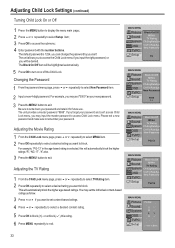
... default password is selected, this rating. 6 Press MENU repeatedly to exit. You may input the master password to block. Changing the Password 1 From the password menu page, press 5or6 repeatedly to access the submenu; 4 Enter password with the number buttons. For example, "PG-13" in the age-based rating is 1234, you want to access Child Lock menu. Adjusting Child Lock Settings (continued) Turning Child Lock On or Off 1 Press the MENU button to display...
... default password is selected, this rating. 6 Press MENU repeatedly to exit. You may input the master password to block. Changing the Password 1 From the password menu page, press 5or6 repeatedly to access the submenu; 4 Enter password with the number buttons. For example, "PG-13" in the age-based rating is 1234, you want to access Child Lock menu. Adjusting Child Lock Settings (continued) Turning Child Lock On or Off 1 Press the MENU button to display...

Operation Manual
Page 38
... your problem is plugged into the mains socket and turn on the unit again. Adjust the contrast, color and brightness settings. !Sometimes, poor picture quality occurs when an activated S-VHS camera or camcorder is connected while another activated peripheral is used in the SOUND menu. !Unplug the power cord, wait for a few seconds. Good sound but no sound !Check video connections at the rear of the speakers Control buttons do not...
... your problem is plugged into the mains socket and turn on the unit again. Adjust the contrast, color and brightness settings. !Sometimes, poor picture quality occurs when an activated S-VHS camera or camcorder is connected while another activated peripheral is used in the SOUND menu. !Unplug the power cord, wait for a few seconds. Good sound but no sound !Check video connections at the rear of the speakers Control buttons do not...

Operation Manual
Page 42
... code for your device power should turn on the Polaroid Universal Remote Control (TV, DVD, CBL, or AUX). Go to control. Repeat steps 2-4, this time choosing the next code in the Device Code Table (see last pages of instructions for programming your Polaroid Universal Remote Control to work with other than a TV, DVD, or Cable Box, use of one of the remote will see the LED blink twice. If you are two sets of your device, you press a numbered button. Release the SET button...
... code for your device power should turn on the Polaroid Universal Remote Control (TV, DVD, CBL, or AUX). Go to control. Repeat steps 2-4, this time choosing the next code in the Device Code Table (see last pages of instructions for programming your Polaroid Universal Remote Control to work with other than a TV, DVD, or Cable Box, use of one of the remote will see the LED blink twice. If you are two sets of your device, you press a numbered button. Release the SET button...

Operation Manual
Page 43
... the device button the red LED at the top of the Device Code Table. 1 Turn the device power off and point the Polaroid Universal Remote Control at the device you press the number 9 button the LED blinks once. Press 3 6 Momentarily press the power button (top-right button) and release it. 7 Press the CH+ button, slowly and repeatedly, until you should operate properly. 40 Auto Code Search Setup This method does not require use the...
... the device button the red LED at the top of the Device Code Table. 1 Turn the device power off and point the Polaroid Universal Remote Control at the device you press the number 9 button the LED blinks once. Press 3 6 Momentarily press the power button (top-right button) and release it. 7 Press the CH+ button, slowly and repeatedly, until you should operate properly. 40 Auto Code Search Setup This method does not require use the...

Service Manual
Page 2
...-6322 Model Part Number Description Boards FLM-3701 667-L37K5-20A 667-L37K7-05 667-L37K7-09 667-L37K7-10 667-L37K7N-40 667-L37K7N-56 301-DL26K7-01A 615-10507-02 615-20430-00 615-20431-00 Power Supply Board KAS20 Keypress Board IR Receive Board Earphone Assy Audio/Video Processing Board CPU Board Remote RC-D01-0A Stand Assy Speaker (left) Speaker...
...-6322 Model Part Number Description Boards FLM-3701 667-L37K5-20A 667-L37K7-05 667-L37K7-09 667-L37K7-10 667-L37K7N-40 667-L37K7N-56 301-DL26K7-01A 615-10507-02 615-20430-00 615-20431-00 Power Supply Board KAS20 Keypress Board IR Receive Board Earphone Assy Audio/Video Processing Board CPU Board Remote RC-D01-0A Stand Assy Speaker (left) Speaker...

Service Manual
Page 4
... not change the specs and type at once. Otherwise it 's necessary to pay attention to use the screen of the original model for all the parts that have to be sure to the detailed list before replacing components that have special safety requirements. Instructions Be sure to switch off the power supply before the pulling out or plugging in the connection wire. 2.8 When operating or installing LCD please don...
... not change the specs and type at once. Otherwise it 's necessary to pay attention to use the screen of the original model for all the parts that have to be sure to the detailed list before replacing components that have special safety requirements. Instructions Be sure to switch off the power supply before the pulling out or plugging in the connection wire. 2.8 When operating or installing LCD please don...

Service Manual
Page 6
... Input VGA signal (one format), check if the display is shown as fig-1 Check DDC and FLASH To produce CPU board and analog board Check the CPU board and analog board All testing Connect with power and observe the display. Note: the white balance adjustment should be done under PC condition, check each function such as analog control etc., check the output of headphone and speaker Input...
... Input VGA signal (one format), check if the display is shown as fig-1 Check DDC and FLASH To produce CPU board and analog board Check the CPU board and analog board All testing Connect with power and observe the display. Note: the white balance adjustment should be done under PC condition, check each function such as analog control etc., check the output of headphone and speaker Input...
Service Manual
Page 8
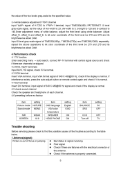
..., press the auto adjust button on remote control again and check if it is normal. 4.4 DVI terminal Insert DVI terminal, input signal of 640 X 480@60 Hz signal and check if the display is normal. 4.5 check sound channel Check the speaker and headphone of each channel. 4.6 presetting before ex-factory item Picture mode Sound mode N/R SCREEN setting NATURE NEWS WEAK 16:9 item OSD language VGA color temperature SPEAKER HEAD PHONE setting English 9300...
..., press the auto adjust button on remote control again and check if it is normal. 4.4 DVI terminal Insert DVI terminal, input signal of 640 X 480@60 Hz signal and check if the display is normal. 4.5 check sound channel Check the speaker and headphone of each channel. 4.6 presetting before ex-factory item Picture mode Sound mode N/R SCREEN setting NATURE NEWS WEAK 16:9 item OSD language VGA color temperature SPEAKER HEAD PHONE setting English 9300...

Service Manual
Page 10
... 's connected to display correct picture signal Method of software upgrading Steps of the picture. Blur picture No sound When playing VHS picture search tape, there are lines at the top or bottom of software upgrading are installed in pause VHS picture search tape sometimes can receive input signal. Check if the cable connection is effective. Check if it has received the right video signal. Use a serial wire to connect the PC to the patch panel and set TV set to...
... 's connected to display correct picture signal Method of software upgrading Steps of the picture. Blur picture No sound When playing VHS picture search tape, there are lines at the top or bottom of software upgrading are installed in pause VHS picture search tape sometimes can receive input signal. Check if the cable connection is effective. Check if it has received the right video signal. Use a serial wire to connect the PC to the patch panel and set TV set to...


