Service Manual
Page 3
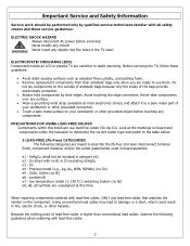
... interconnect terminal finish, component material, and/or the solder paste/solder used in board assembly: e1 - Sn e4 - Before servicing the TV, follow these service guidelines: ELECTRIC SHOCK HAZARD Always disconnect AC power before touching any surface. • Wear a grounding wrist strap (available at ...bare metal part of antistatic bags because only the inside an LCD or plasma TV are unassigned at the markings on your workbench or other grounded connection. • Touch a bare metal surface on board and components within this time. Because the melting point of the...
... interconnect terminal finish, component material, and/or the solder paste/solder used in board assembly: e1 - Sn e4 - Before servicing the TV, follow these service guidelines: ELECTRIC SHOCK HAZARD Always disconnect AC power before touching any surface. • Wear a grounding wrist strap (available at ...bare metal part of antistatic bags because only the inside an LCD or plasma TV are unassigned at the markings on your workbench or other grounded connection. • Touch a bare metal surface on board and components within this time. Because the melting point of the...

Service Manual
Page 20
...grounding wrist strap (available at most electronics stores) and attach it to a bare metal part of any part the TV, make sure the power is OFF, and the power cord is large enough to static electricity. Avoid touching the edge connectors. This procedure ensures that are sensitive to hold...surface that is removed from their edges. When servicing an LCD or plasma TV, always observe the following safety guidelines: • Wear a grounding (ESD) wrist strap, and use them. 5. Allow time for power within all system boards to discharge before removing the screws to the component on your...
...grounding wrist strap (available at most electronics stores) and attach it to a bare metal part of any part the TV, make sure the power is OFF, and the power cord is large enough to static electricity. Avoid touching the edge connectors. This procedure ensures that are sensitive to hold...surface that is removed from their edges. When servicing an LCD or plasma TV, always observe the following safety guidelines: • Wear a grounding (ESD) wrist strap, and use them. 5. Allow time for power within all system boards to discharge before removing the screws to the component on your...
Service Manual
Page 21
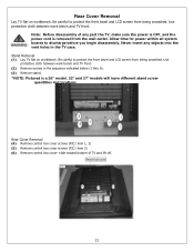
... power within all system boards to protect the front bezel and LCD screen from being scratched. Rear Cover Removal (4) Remove control box cover screws (PIC1 item 1, 2) (5) Remove control box cover screws (PIC1 item 3) (6) Remove control box cover- Use protective cloth between work bench and TV front. Never insert any part the TV, make sure the power...
... power within all system boards to protect the front bezel and LCD screen from being scratched. Rear Cover Removal (4) Remove control box cover screws (PIC1 item 1, 2) (5) Remove control box cover screws (PIC1 item 3) (6) Remove control box cover- Use protective cloth between work bench and TV front. Never insert any part the TV, make sure the power...
Service Manual
Page 23
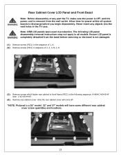
... Remove rear cabinet cover. Ensure LCD panel is not damaged. (1) Remove screws (PIC1) in the sequence of 1, A. (2) Remove screws (PIC1) in sequence of any objects into the vent holes in the TV case. Allow time for power within all system boards to discharge before removing so the... and locations. 23 Never insert any part the TV, make sure the power is OFF, and the power cord is a 26" model. 32" and 37" models will come off. *NOTE: Pictured is removed from the bezel before you begin disassembly. Rear Cabinet Cover LCD Panel and Front Bezel Note: Before disassembly of ...
... Remove rear cabinet cover. Ensure LCD panel is not damaged. (1) Remove screws (PIC1) in the sequence of 1, A. (2) Remove screws (PIC1) in sequence of any objects into the vent holes in the TV case. Allow time for power within all system boards to discharge before removing so the... and locations. 23 Never insert any part the TV, make sure the power is OFF, and the power cord is a 26" model. 32" and 37" models will come off. *NOTE: Pictured is removed from the bezel before you begin disassembly. Rear Cabinet Cover LCD Panel and Front Bezel Note: Before disassembly of ...

Service Manual
Page 29
... degrees. Do the same for power within all system boards to discharge before you must follow the steps outlined in the section, Before Returning This Product to the User, on page 19. Never insert any part the TV, make sure the power is OFF, and the power cord is removed from the wall... outlet. Allow time for the opposite side of the A/V assembly. (3) Slide out A/V board and replace (PIC2). (4) Push locking tabs in the TV case. (1) Disassemble control box cover and rear ...
... degrees. Do the same for power within all system boards to discharge before you must follow the steps outlined in the section, Before Returning This Product to the User, on page 19. Never insert any part the TV, make sure the power is OFF, and the power cord is removed from the wall... outlet. Allow time for the opposite side of the A/V assembly. (3) Slide out A/V board and replace (PIC2). (4) Push locking tabs in the TV case. (1) Disassemble control box cover and rear ...
Service Manual
Page 30
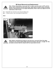
... the end user, you begin disassembly. IR Board Removal and Replacement Note: Before disassembly of any objects into the vent holes in the section, Before Returning This Product to discharge before you must follow the steps outlined in the TV case. (1) Disassemble rear control box cover and... rear cabinet cover. (2) 2. Never insert any part the TV, make sure the power is OFF, and the power cord is removed from the wall outlet. Remove screws 1 and 2 and replace IR board (PIC1). This procedure ensures ...
... the end user, you begin disassembly. IR Board Removal and Replacement Note: Before disassembly of any objects into the vent holes in the section, Before Returning This Product to discharge before you must follow the steps outlined in the TV case. (1) Disassemble rear control box cover and... rear cabinet cover. (2) 2. Never insert any part the TV, make sure the power is OFF, and the power cord is removed from the wall outlet. Remove screws 1 and 2 and replace IR board (PIC1). This procedure ensures ...

Service Manual
Page 31
... you must follow the steps outlined in the TV case. (1) Disassemble control box cover and rear cabinet cover. (2) The control button board is removed from the wall outlet. Never insert any part the TV, make sure the power is OFF, and the power cord is attached with glue. This procedure ensures... that the chassis will not cause electric shock. 31 Use alcohol to soften the glue and remove the control button board (PIC1). (3) Replace control button board and use glue to...
... you must follow the steps outlined in the TV case. (1) Disassemble control box cover and rear cabinet cover. (2) The control button board is removed from the wall outlet. Never insert any part the TV, make sure the power is OFF, and the power cord is attached with glue. This procedure ensures... that the chassis will not cause electric shock. 31 Use alcohol to soften the glue and remove the control button board (PIC1). (3) Replace control button board and use glue to...
Service Manual
Page 38
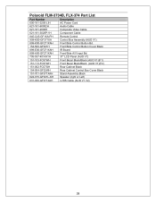
Polaroid FLM-3734B, FLX-374 Part List Part Number Description 600-181-3200-LIH AC Power Cord 621-181-60002H Audio Cable 621-181-2000H Composite Video Cable 621-181-3020P-1H Component Cable 845-C45-GF1XA-PH Remote Control 909-...-K00-GF271XAH Front/Side Control Button Bd. 154-500-GF321H Front/Side Control Button Cover Black 899-E00-GF271XAH IR Board 899-A00-GF271XAH Front/Side A/V Input Bd. 705-537-401AX1H 37" LCD Panel (AUO V1) 151-103-FC57WH Front Bezel Black/Black (AUO V1)(F1) 151-113-FC57WH Front Bezel Black...
Polaroid FLM-3734B, FLX-374 Part List Part Number Description 600-181-3200-LIH AC Power Cord 621-181-60002H Audio Cable 621-181-2000H Composite Video Cable 621-181-3020P-1H Component Cable 845-C45-GF1XA-PH Remote Control 909-...-K00-GF271XAH Front/Side Control Button Bd. 154-500-GF321H Front/Side Control Button Cover Black 899-E00-GF271XAH IR Board 899-A00-GF271XAH Front/Side A/V Input Bd. 705-537-401AX1H 37" LCD Panel (AUO V1) 151-103-FC57WH Front Bezel Black/Black (AUO V1)(F1) 151-113-FC57WH Front Bezel Black...
Service Manual
Page 50
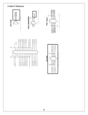
... IR-OUT 5 LTDC_INT 3 LTDC_DATA 1 16 SW7-VOL-DOWN 14 SW5-CH-DOWN 12 SW3-MENU 10 SW1-POWER 8 LED_O 6 LTDC_ADDR 4 LTDC_CLK 2 200PHD-16LT CTRL. Key 200PHD Series 2X7 (14pin) CON2 PHONE_A_D_O 13 14 ...12 FRONT_A_L_IN 9 10 7 8 FRONT_COMPOSITE 5 6 3 4 FRONT_S_CHROMA 1 2 PHONE_A_L_O PHONE_A_R_O FRONT_A_R_IN FRONT_S_LUMA 200PHD-14LT AUX AV D-SUB 37 PIN Board 5 0 200PHD Series 2X4 (8pin) CON3 VBLON ADJ_INV 7 8 5 6 3 4 1 2 200PHD-8LT INVERTER CTRL. 250XH Series 1X4...33 14 32 13 31 12 30 11 29 10 28 9 27 8 26 7 25 6 24 5 23 4 22 3 21 2 20 1 D-SUB 37P ...
... IR-OUT 5 LTDC_INT 3 LTDC_DATA 1 16 SW7-VOL-DOWN 14 SW5-CH-DOWN 12 SW3-MENU 10 SW1-POWER 8 LED_O 6 LTDC_ADDR 4 LTDC_CLK 2 200PHD-16LT CTRL. Key 200PHD Series 2X7 (14pin) CON2 PHONE_A_D_O 13 14 ...12 FRONT_A_L_IN 9 10 7 8 FRONT_COMPOSITE 5 6 3 4 FRONT_S_CHROMA 1 2 PHONE_A_L_O PHONE_A_R_O FRONT_A_R_IN FRONT_S_LUMA 200PHD-14LT AUX AV D-SUB 37 PIN Board 5 0 200PHD Series 2X4 (8pin) CON3 VBLON ADJ_INV 7 8 5 6 3 4 1 2 200PHD-8LT INVERTER CTRL. 250XH Series 1X4...33 14 32 13 31 12 30 11 29 10 28 9 27 8 26 7 25 6 24 5 23 4 22 3 21 2 20 1 D-SUB 37P ...

