
Service Manual
Page 2
... controls that are not sure of the type of power available, consult your obsolete outlet. The product may touch dangerous voltage points or short out parts that could result in a risk of fire or electric shock. This plug will walk on the cord. (11) If an extension cord is provided. (8) This...
... controls that are not sure of the type of power available, consult your obsolete outlet. The product may touch dangerous voltage points or short out parts that could result in a risk of fire or electric shock. This plug will walk on the cord. (11) If an extension cord is provided. (8) This...
Service Manual
Page 3
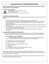
...metal (e.g., Ag, Au, NiPd, NiPdAu) (no Bi) e6 - Because the melting point of antistatic bags because only the inside an LCD or plasma TV are meant to describe the Pb-free 2nd level interconnect terminal finish, component material, and/or the solder paste/solder used in fire,...power before touching any surface. • Wear a grounding wrist strap (available at most electronics stores) and attach it to a bare metal part of the bags provide electrostatic protection. • Always hold components by qualified service technicians familiar with lead-free solder: 3 Never slide components ...
...metal (e.g., Ag, Au, NiPd, NiPdAu) (no Bi) e6 - Because the melting point of antistatic bags because only the inside an LCD or plasma TV are meant to describe the Pb-free 2nd level interconnect terminal finish, component material, and/or the solder paste/solder used in fire,...power before touching any surface. • Wear a grounding wrist strap (available at most electronics stores) and attach it to a bare metal part of the bags provide electrostatic protection. • Always hold components by qualified service technicians familiar with lead-free solder: 3 Never slide components ...

Service Manual
Page 4
...with steel wool or fine sandpaper. (0) NOTICE ABOUT REPLACEMENT PARTS Many electrical and mechanical parts within LCD or plasma televisions are chosen for their specific safety characteristics within the overall system. Unauthorized substitute parts may result in contact with components rated for higher voltage ... used in the television. Replacing individual parts with a lead-free solder bit, subsequent solder joints will no longer be dangerous! Replacement parts must always be easily corroded or damaged. Leaving the bit in contact with parts for extended periods. If a different ...
...with steel wool or fine sandpaper. (0) NOTICE ABOUT REPLACEMENT PARTS Many electrical and mechanical parts within LCD or plasma televisions are chosen for their specific safety characteristics within the overall system. Unauthorized substitute parts may result in contact with components rated for higher voltage ... used in the television. Replacing individual parts with a lead-free solder bit, subsequent solder joints will no longer be dangerous! Replacement parts must always be easily corroded or damaged. Leaving the bit in contact with parts for extended periods. If a different ...
Service Manual
Page 5
... to obtain User Manual. 5 Spare Parts Lists - FLM-Series 26, 32, 37 32 7. Exploded View Diagram ...39 8. FLM-Series 26, 32, 37 42 9. Polaroid Display Cell Defect Specification 18 4. PCB Layout Diagrams ...51 Model Specifications are located in User Manual. Disassembly Procedure...20 Rear Cover Removal ...21 Rear Cabinet Cover LCD Panel and Front Bezel 23 A/V Board...
... to obtain User Manual. 5 Spare Parts Lists - FLM-Series 26, 32, 37 32 7. Exploded View Diagram ...39 8. FLM-Series 26, 32, 37 42 9. Polaroid Display Cell Defect Specification 18 4. PCB Layout Diagrams ...51 Model Specifications are located in User Manual. Disassembly Procedure...20 Rear Cover Removal ...21 Rear Cabinet Cover LCD Panel and Front Bezel 23 A/V Board...
Service Manual
Page 14
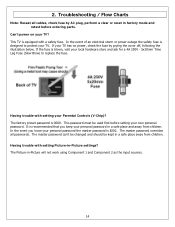
... power on your Parental Controls (V-Chip)? Troubleshooting / Flow Charts Note: Reseat all passwords. If the fuse is recommended that you loose your TV has no power, check the fuse by AC plug, perform a clear or reset in a safe place away from children. The master password... can't be changed and should be used first before ordering parts. The Picture-in -Picture settings? 2. The factory preset password is equipped with setting your TV? Having trouble with a safety fuse. The master password overrides all cables, check fuse by ...
... power on your Parental Controls (V-Chip)? Troubleshooting / Flow Charts Note: Reseat all passwords. If the fuse is recommended that you loose your TV has no power, check the fuse by AC plug, perform a clear or reset in a safe place away from children. The master password... can't be changed and should be used first before ordering parts. The Picture-in -Picture settings? 2. The factory preset password is equipped with setting your TV? Having trouble with a safety fuse. The master password overrides all cables, check fuse by ...

Service Manual
Page 19
Plug the AC cord directly into a 120 V AC outlet. Measurement points include antenna, metal cabinet parts, screw heads, and metal knobs or controls. Under normal operation the product must use the proper polarity. 19 Any voltage reading of a 1.5k ohm,.... Before Returning This Product to the User Before returning this product to be sure no shock hazard exists on any part of the chassis, especially any metal parts. (2) Inspect all exposed metallic parts and a known earth ground. Use the following safety checks: (1) Inspect all wiring to the user, always perform the ...
Plug the AC cord directly into a 120 V AC outlet. Measurement points include antenna, metal cabinet parts, screw heads, and metal knobs or controls. Under normal operation the product must use the proper polarity. 19 Any voltage reading of a 1.5k ohm,.... Before Returning This Product to the User Before returning this product to be sure no shock hazard exists on any part of the chassis, especially any metal parts. (2) Inspect all exposed metallic parts and a known earth ground. Use the following safety checks: (1) Inspect all wiring to the user, always perform the ...

Service Manual
Page 20
... cable. • Use a magnetized screwdriver for removing screws. • To help keep track of antistatic bags because only the inside an LCD or plasma TV are ready to the component on the outside of screws, place each component's screws next to use a grounded or dissipative work mat. •...; Use a stable and strong work surface. Never slide components over any components. 20 Never insert any part the TV, make sure the power is OFF, and the power cord is large enough to hold components by their antistatic bags only when you might ...
... cable. • Use a magnetized screwdriver for removing screws. • To help keep track of antistatic bags because only the inside an LCD or plasma TV are ready to the component on the outside of screws, place each component's screws next to use a grounded or dissipative work mat. •...; Use a stable and strong work surface. Never slide components over any components. 20 Never insert any part the TV, make sure the power is OFF, and the power cord is large enough to hold components by their antistatic bags only when you might ...
Service Manual
Page 21
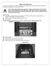
... any part the TV, make sure the power is OFF, and the power cord is a 26" model. 32" and 37" models will have different stand screw quantities and locations. Use protective cloth between work bench and TV front. (2) Remove screws in the TV case. Note: Before disassembly of TV and lift.... Allow time for power within all system boards to protect the front bezel and LCD screen from the wall outlet. Stand Removal (1) Lay TV flat on workbench. Be careful to protect the front bezel and LCD screen from being scratched. Rear Cover Removal (4) Remove control box cover screws (PIC1...
... any part the TV, make sure the power is OFF, and the power cord is a 26" model. 32" and 37" models will have different stand screw quantities and locations. Use protective cloth between work bench and TV front. (2) Remove screws in the TV case. Note: Before disassembly of TV and lift.... Allow time for power within all system boards to protect the front bezel and LCD screen from the wall outlet. Stand Removal (1) Lay TV flat on workbench. Be careful to protect the front bezel and LCD screen from being scratched. Rear Cover Removal (4) Remove control box cover screws (PIC1...
Service Manual
Page 23
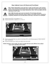
... all models. Only the rear cabinet cover will have some different rear cabinet cover screw quantities and locations. 23 Note: OEM LCD panels were used in the TV case. Rear Cabinet Cover LCD Panel and Front Bezel Note: Before disassembly of 2, 3, 4, B, C, D (3) Remove screws which fasten rear cabinet to front...PIC1) in sequence of any objects into the vent holes in production. Ensure LCD panel is completely detached from the wall outlet. Never insert any part the TV, make sure the power is OFF, and the power cord is a 26" model. 32" and 37" models will come off. *NOTE: Pictured...
... all models. Only the rear cabinet cover will have some different rear cabinet cover screw quantities and locations. 23 Note: OEM LCD panels were used in the TV case. Rear Cabinet Cover LCD Panel and Front Bezel Note: Before disassembly of 2, 3, 4, B, C, D (3) Remove screws which fasten rear cabinet to front...PIC1) in sequence of any objects into the vent holes in production. Ensure LCD panel is completely detached from the wall outlet. Never insert any part the TV, make sure the power is OFF, and the power cord is a 26" model. 32" and 37" models will come off. *NOTE: Pictured...

Service Manual
Page 29
...power within all system boards to discharge before you must follow the steps outlined in to secure replaced A/V board. Never insert any part the TV, make sure the power is OFF, and the power cord is removed from the wall outlet. Locking tabl should only pivot about ... this product to the end user, you begin disassembly. A/V Board Removal and Replacement Note: Before disassembly of any objects into the vent holes in the TV case. (1) Disassemble control box cover and rear cabinet cover and remove A/V assembly. (2) Using a small pair of the A/V assembly. (3) Slide out A/V board ...
...power within all system boards to discharge before you must follow the steps outlined in to secure replaced A/V board. Never insert any part the TV, make sure the power is OFF, and the power cord is removed from the wall outlet. Locking tabl should only pivot about ... this product to the end user, you begin disassembly. A/V Board Removal and Replacement Note: Before disassembly of any objects into the vent holes in the TV case. (1) Disassemble control box cover and rear cabinet cover and remove A/V assembly. (2) Using a small pair of the A/V assembly. (3) Slide out A/V board ...
Service Manual
Page 30
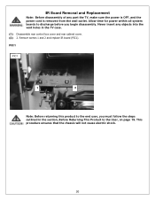
Remove screws 1 and 2 and replace IR board (PIC1). Allow time for power within all system boards to the User, on page 19. Never insert any part the TV, make sure the power is OFF, and the power cord is removed from the wall outlet. This procedure ensures that the chassis will not cause... of any objects into the vent holes in the section, Before Returning This Product to discharge before you must follow the steps outlined in the TV case. (1) Disassemble rear control box cover and rear cabinet cover. (2) 2.
Remove screws 1 and 2 and replace IR board (PIC1). Allow time for power within all system boards to the User, on page 19. Never insert any part the TV, make sure the power is OFF, and the power cord is removed from the wall outlet. This procedure ensures that the chassis will not cause... of any objects into the vent holes in the section, Before Returning This Product to discharge before you must follow the steps outlined in the TV case. (1) Disassemble rear control box cover and rear cabinet cover. (2) 2.

Service Manual
Page 31
.... (1) Disassemble control box cover and rear cabinet cover. (2) The control button board is removed from the wall outlet. Never insert any part the TV, make sure the power is OFF, and the power cord is attached with glue. Front/Side Control Buttons Removal and Replacement Note: Before disassembly of ...
.... (1) Disassemble control box cover and rear cabinet cover. (2) The control button board is removed from the wall outlet. Never insert any part the TV, make sure the power is OFF, and the power cord is attached with glue. Front/Side Control Buttons Removal and Replacement Note: Before disassembly of ...

Service Manual
Page 32
.... Reference the serial number format details below to identify the replacement part(s) needed for this model. Service bulletins can be obtained through your Polaroid service contact. In the event the TV Model Version is used to identify the correct replacement part(s) before ordering parts. 32 Below is replaced with multiple versions. DETAILS 06 00 01...
.... Reference the serial number format details below to identify the replacement part(s) needed for this model. Service bulletins can be obtained through your Polaroid service contact. In the event the TV Model Version is used to identify the correct replacement part(s) before ordering parts. 32 Below is replaced with multiple versions. DETAILS 06 00 01...
Service Manual
Page 38
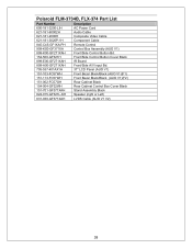
Polaroid FLM-3734B, FLX-374 Part List Part Number Description 600-181-3200-LIH AC Power Cord 621-181-60002H Audio Cable 621-181-2000H Composite Video Cable 621-181-3020P-1H Component .... 154-500-GF321H Front/Side Control Button Cover Black 899-E00-GF271XAH IR Board 899-A00-GF271XAH Front/Side A/V Input Bd. 705-537-401AX1H 37" LCD Panel (AUO V1) 151-103-FC57WH Front Bezel Black/Black (AUO V1)(F1) 151-113-FC57WH Front Bezel Black/Black (AUO V1)(F2) 151-002...
Polaroid FLM-3734B, FLX-374 Part List Part Number Description 600-181-3200-LIH AC Power Cord 621-181-60002H Audio Cable 621-181-2000H Composite Video Cable 621-181-3020P-1H Component .... 154-500-GF321H Front/Side Control Button Cover Black 899-E00-GF271XAH IR Board 899-A00-GF271XAH Front/Side A/V Input Bd. 705-537-401AX1H 37" LCD Panel (AUO V1) 151-103-FC57WH Front Bezel Black/Black (AUO V1)(F1) 151-113-FC57WH Front Bezel Black/Black (AUO V1)(F2) 151-002...


