Technical Manual
Page 2
...TO USE THE STANDARD MOUNTING COMPONENTS 4.1 Standard Mounting Components Features and Characteristics 50 4.2 Handling the Standard Mounting Components 51 4.2.1 Handling precautions 51 4.2.2 ...and Installing the mounting hardware and mounting the plasma display ...... 76 4.8.4 Assembly procedure 77 4.8.5 Angle setup 78 4.9 Tiltable Plasma Display Wall-Mount Hardware: PDK-5013 80 ...Installation on the PDP-503CMX or PDP-503MXE 94 BEFORE BEGINNING ADJUSTMENTS 5.1 Before Beginning Adjustments 96 5.1.1 Operating mode 96 5.1.2 Combination use of remote control unit, operating panel and PC 97...
...TO USE THE STANDARD MOUNTING COMPONENTS 4.1 Standard Mounting Components Features and Characteristics 50 4.2 Handling the Standard Mounting Components 51 4.2.1 Handling precautions 51 4.2.2 ...and Installing the mounting hardware and mounting the plasma display ...... 76 4.8.4 Assembly procedure 77 4.8.5 Angle setup 78 4.9 Tiltable Plasma Display Wall-Mount Hardware: PDK-5013 80 ...Installation on the PDP-503CMX or PDP-503MXE 94 BEFORE BEGINNING ADJUSTMENTS 5.1 Before Beginning Adjustments 96 5.1.1 Operating mode 96 5.1.2 Combination use of remote control unit, operating panel and PC 97...
Technical Manual
Page 6
Specifications 2.1 Specifications Light-emitting panel 50-inch plasma display panel Aspect ratio 16 : 9 PEL 1280 × 768 PEL pitch 0.858 (H•RGB trio) × 0.808 (V) mm Viewing angle Horizontal: more than 160 ...mini-jack (× 2) Power requirements AC 100 V to 120 V, 50/60 Hz In-rush less than 30 A Power factor more than three tiers Standard accessories Power cord 1 Remote control unit 1 AA battery 2 Wiping cloth 1 Speed clamp 2 Bead Band 2 Operating instructions 1 Warranty card 1 Remote control unit holder 1 Display stand 2 Washer 2 Hexagon socket head screw ...
Specifications 2.1 Specifications Light-emitting panel 50-inch plasma display panel Aspect ratio 16 : 9 PEL 1280 × 768 PEL pitch 0.858 (H•RGB trio) × 0.808 (V) mm Viewing angle Horizontal: more than 160 ...mini-jack (× 2) Power requirements AC 100 V to 120 V, 50/60 Hz In-rush less than 30 A Power factor more than three tiers Standard accessories Power cord 1 Remote control unit 1 AA battery 2 Wiping cloth 1 Speed clamp 2 Bead Band 2 Operating instructions 1 Warranty card 1 Remote control unit holder 1 Display stand 2 Washer 2 Hexagon socket head screw ...

Technical Manual
Page 7
...93.8kHz 106.3kHz Remark Apple Macintosh 21" Sun Microsystems LO Sun Microsystems HI (1600 x 1024) 7 This setting can be changed using either the remote control unit or a PC. Specifications (NOTE 1) (NOTE 2) (NOTE 3) The display is preset at the factory to Installation Site Requirements.) INPUT Response Signals... INPUT 1, 2 & Video signals supported # Vertical Horizontal Frequency Frequency Fv (Hz) Fh (kHz) 15.625 50 28.1 31.25 15.734 31.5 60 33.75 45.0 67.5 Signal Format Component RGB Component RGB Component RGB Component RGB Component RGB...
...93.8kHz 106.3kHz Remark Apple Macintosh 21" Sun Microsystems LO Sun Microsystems HI (1600 x 1024) 7 This setting can be changed using either the remote control unit or a PC. Specifications (NOTE 1) (NOTE 2) (NOTE 3) The display is preset at the factory to Installation Site Requirements.) INPUT Response Signals... INPUT 1, 2 & Video signals supported # Vertical Horizontal Frequency Frequency Fv (Hz) Fh (kHz) 15.625 50 28.1 31.25 15.734 31.5 60 33.75 45.0 67.5 Signal Format Component RGB Component RGB Component RGB Component RGB Component RGB...

Technical Manual
Page 11
... operations is clearly indicated in operation or standby mode. 5 KEY LOCK/UNLOCK Button (concealed button) This switches between main unit panel and remote control operation permitted/forbidden. 6 INPUT button Press to select input. 7 MENU button Press to open and close the on-screen menu...select the screen size. - Note When optional speakers have been connected, the operation panel on the main unit 4 5 6 7 8 9 0 - 1 2 Main unit 1 Display stand 2 Remote control sensor Point the remote control toward the remote sensor to operate the unit. 3 STANDBY/ON indicator This indicator is in the ...
... operations is clearly indicated in operation or standby mode. 5 KEY LOCK/UNLOCK Button (concealed button) This switches between main unit panel and remote control operation permitted/forbidden. 6 INPUT button Press to select input. 7 MENU button Press to open and close the on-screen menu...select the screen size. - Note When optional speakers have been connected, the operation panel on the main unit 4 5 6 7 8 9 0 - 1 2 Main unit 1 Display stand 2 Remote control sensor Point the remote control toward the remote sensor to operate the unit. 3 STANDBY/ON indicator This indicator is in the ...

Technical Manual
Page 12
...INPUT OUTPUT (INPUT1/2) 56 7 89 0 Plasma Display Section 1 SPEAKER (R) terminal For connection of the source used for performing separate sink or composite sink input and output is that bear the Î mark. But a condition for adjustments by the wired remote control RV-V107. 3 COMBINATION IN/OUT Used... 4 RS-232C This terminal is used is 8 -16 Ω. 2 CONTROL IN/OUT (monaural mini jacks) For connection of PIONEER components that the sink level of an external right speaker. Making CONTROL connection enables control of the main unit as the connecting cable. (NOTE) It has no ...
...INPUT OUTPUT (INPUT1/2) 56 7 89 0 Plasma Display Section 1 SPEAKER (R) terminal For connection of the source used for performing separate sink or composite sink input and output is that bear the Î mark. But a condition for adjustments by the wired remote control RV-V107. 3 COMBINATION IN/OUT Used... 4 RS-232C This terminal is used is 8 -16 Ω. 2 CONTROL IN/OUT (monaural mini jacks) For connection of PIONEER components that the sink level of an external right speaker. Making CONTROL connection enables control of the main unit as the connecting cable. (NOTE) It has no ...
Technical Manual
Page 15
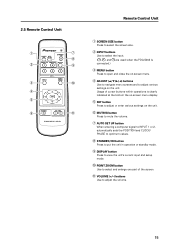
Remote Control Unit 1 SCREEN SIZE button Press to select the screen size. 2 INPUT buttons Use to select the input. ( , , and are used when the PDA-5002 is ... and to adjust the volume. 15 Usage of cursor buttons within operations is connected.) 3 MENU button Press to open and close the on the unit. 2.5 Remote Control Unit 1 7 8 2 9 3 0 4 5 6 -
Remote Control Unit 1 SCREEN SIZE button Press to select the screen size. 2 INPUT buttons Use to select the input. ( , , and are used when the PDA-5002 is ... and to adjust the volume. 15 Usage of cursor buttons within operations is connected.) 3 MENU button Press to open and close the on the unit. 2.5 Remote Control Unit 1 7 8 2 9 3 0 4 5 6 -

Technical Manual
Page 16
Area of remote control unit holder attachment Example of the main unit or some other fixed surface, so that it will be available for putting away the remote control unit when it to the rear of remote control unit holder attachment Remote control unit Remote control unit holder Upper and lower tape (NOTE) Do not obstruct the ventilation holes in use. Remote Control Unit Holder 2.6 Remote Control Unit Holder Peel the sticker paper off of the lower and upper tape on the rear side of the remote control unit holder, and attach it is not in the remote control unit holder. 16
Area of remote control unit holder attachment Example of the main unit or some other fixed surface, so that it will be available for putting away the remote control unit when it to the rear of remote control unit holder attachment Remote control unit Remote control unit holder Upper and lower tape (NOTE) Do not obstruct the ventilation holes in use. Remote Control Unit Holder 2.6 Remote Control Unit Holder Peel the sticker paper off of the lower and upper tape on the rear side of the remote control unit holder, and attach it is not in the remote control unit holder. 16

Technical Manual
Page 19
...high humidity, observe the following occurs, contact an electrician to install the unit in each country flows from the display or contact Pioneer authorized dealer for 400 W ≠ 400 VA of power lines may be affected. The screen's infrared intensity will vary, ...the following : • Failure to inspect the power. • Significant voltage drop between the circuit panel and the plasma display • Significant changes in the wiring system. 12) Effective remote control distance This display emits weak infrared radiation. When using a power source use conversion plug, insert it...
...high humidity, observe the following occurs, contact an electrician to install the unit in each country flows from the display or contact Pioneer authorized dealer for 400 W ≠ 400 VA of power lines may be affected. The screen's infrared intensity will vary, ...the following : • Failure to inspect the power. • Significant voltage drop between the circuit panel and the plasma display • Significant changes in the wiring system. 12) Effective remote control distance This display emits weak infrared radiation. When using a power source use conversion plug, insert it...

Technical Manual
Page 24
...same way as when they were originally shipped. Terms 1 Upper face of the carton 2 Carton cover 3 Lower face of the carton. 5 Plasma display is important to use the material can be done by its packaging should be re-used to prevent it vertically - No. Installation Procedures... and instructions on the upper face of the carton 4 Pad 5 Pad (Common) 6 Pad 2 7 Pad 8 Miller mat 9 Power cord 4 10 Remote control unit 11 2 manganese AA batteries, R6P 12 Operating instructions 19 5 13 Warranty card 14 Display stand 15 Wiping cloth 9 16 Binder Assembly 17 Bolt, Washer...
...same way as when they were originally shipped. Terms 1 Upper face of the carton 2 Carton cover 3 Lower face of the carton. 5 Plasma display is important to use the material can be done by its packaging should be re-used to prevent it vertically - No. Installation Procedures... and instructions on the upper face of the carton 4 Pad 5 Pad (Common) 6 Pad 2 7 Pad 8 Miller mat 9 Power cord 4 10 Remote control unit 11 2 manganese AA batteries, R6P 12 Operating instructions 19 5 13 Warranty card 14 Display stand 15 Wiping cloth 9 16 Binder Assembly 17 Bolt, Washer...


