Service Manual
Page 1
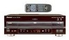
... by Region No. LTD. 253 Alexandra Road, #04-01, Singapore 159936 PIONEER CORPORATION 1999 T - P.O. CONTENTS 1. ZZE AUG. 1999 Printed in Japan RRV2194 THIS MANUAL IS APPLICABLE TO THE FOLLOWING MODEL(S) AND TYPE(S). Type Model DVL-919 (1) Power Requirement The voltage can be confirmed with the following method. Remarks DVL-919/KU/CA RRV2089 DVL-919 has two models which specifications are different. CONTRAST OF MISCELLANEOUS PARTS ........ 2 2. Box 1760...
... by Region No. LTD. 253 Alexandra Road, #04-01, Singapore 159936 PIONEER CORPORATION 1999 T - P.O. CONTENTS 1. ZZE AUG. 1999 Printed in Japan RRV2194 THIS MANUAL IS APPLICABLE TO THE FOLLOWING MODEL(S) AND TYPE(S). Type Model DVL-919 (1) Power Requirement The voltage can be confirmed with the following method. Remarks DVL-919/KU/CA RRV2089 DVL-919 has two models which specifications are different. CONTRAST OF MISCELLANEOUS PARTS ........ 2 2. Box 1760...
Service Manual
Page 2
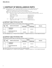
... PCB ASSEMBLIES, Refer to use parts of the part. SCHEMATIC DIAGRAM" and "3. in our Master Spare Parts List. ÷ The mark found on the "EXPLODED VIEWS". ¶ For PCB ASSEMBLIES, Refer to the numbers on some component parts indicates the importance of the safety factor of identical designation. ÷ Reference Nos. Mark Symbol and Description Part No. PCB CONNECTION DIAGRAM". 7 CONTRAST TABLE FOR RD...
... PCB ASSEMBLIES, Refer to use parts of the part. SCHEMATIC DIAGRAM" and "3. in our Master Spare Parts List. ÷ The mark found on the "EXPLODED VIEWS". ¶ For PCB ASSEMBLIES, Refer to the numbers on some component parts indicates the importance of the safety factor of identical designation. ÷ Reference Nos. Mark Symbol and Description Part No. PCB CONNECTION DIAGRAM". 7 CONTRAST TABLE FOR RD...
Service Manual
Page 3
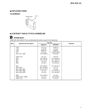
7 EXPLODED VIEWS ÷ EXTERIOR Rear Cover No. 1 DVL-919 (1) 7 CONTRAST TABLE OF PCB ASSEMBLIES I F DVDM ASSY VWS1397 and VWS1377 are constructed the same except for the following: Mark Symbol and Description Part No. VWS1377 VWS1397 IC451 IC603 IC801 C451 C813, C814, C826 Not used VYW1639 MB86371C Not used CEV101M6R3 PQ2TZ15 VYW1657 MB86373 CKSQYF105Z16 CEV221M4 C899 (2.2µF) R801 R816...
7 EXPLODED VIEWS ÷ EXTERIOR Rear Cover No. 1 DVL-919 (1) 7 CONTRAST TABLE OF PCB ASSEMBLIES I F DVDM ASSY VWS1397 and VWS1377 are constructed the same except for the following: Mark Symbol and Description Part No. VWS1377 VWS1397 IC451 IC603 IC801 C451 C813, C814, C826 Not used VYW1639 MB86371C Not used CEV101M6R3 PQ2TZ15 VYW1657 MB86373 CKSQYF105Z16 CEV221M4 C899 (2.2µF) R801 R816...
Service Manual
Page 5
5 6 7 8 DVL-919 (1) Note : When ordering service parts, be sure to refer to "EXPLODED VIEWS and PARTS LIST" or "PCB PARTS LIST". A I 1/3 CN902 VKN1426 I 2/3 J 1/3 CN111 I 2/3 HIBSEL,48/X44,XRESET,XLT3 B I 2/3 CN901 VKN1426 J 2/3 CN122 I 1/3 C CN903 S13B-PH-SMB K 2/2 CN601 D I 2/3 I 5 5 6 7 8
5 6 7 8 DVL-919 (1) Note : When ordering service parts, be sure to refer to "EXPLODED VIEWS and PARTS LIST" or "PCB PARTS LIST". A I 1/3 CN902 VKN1426 I 2/3 J 1/3 CN111 I 2/3 HIBSEL,48/X44,XRESET,XLT3 B I 2/3 CN901 VKN1426 J 2/3 CN122 I 1/3 C CN903 S13B-PH-SMB K 2/2 CN601 D I 2/3 I 5 5 6 7 8
Service Manual
Page 6
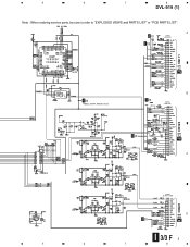
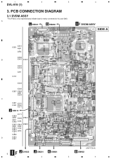
A L CN101 O CN202 4 I F DVDM ASSY SIDE A IC501 IC601 Q401 | Q403 IC506 B IC401 VC301 IC302 IC303 Q301 IC701 IC203 IC202 IC807 IC806 Q291 IC204 C IC801 IC151 IC451 IC161 IC271 J CN111 IC171 IC824 Q802 IC206 Q801 IC902 Q105 VR801 IC815 IC816 Q891 Q455 IC813 Q102 IC814 IC818 Q873 | IC820 VR891 D IC810 IC811 I 6 1 J CN122 J CN201 2 K CN601 (VNP1735-A) D CN902 3 4 Middle layer is a four-layered board. PCB CONNECTION DIAGRAM 3.1 DVDM ASSY • This PCB is mainly connected to Vcc and GND. 1 2 3 DVL-919 (1) 3.
A L CN101 O CN202 4 I F DVDM ASSY SIDE A IC501 IC601 Q401 | Q403 IC506 B IC401 VC301 IC302 IC303 Q301 IC701 IC203 IC202 IC807 IC806 Q291 IC204 C IC801 IC151 IC451 IC161 IC271 J CN111 IC171 IC824 Q802 IC206 Q801 IC902 Q105 VR801 IC815 IC816 Q891 Q455 IC813 Q102 IC814 IC818 Q873 | IC820 VR891 D IC810 IC811 I 6 1 J CN122 J CN201 2 K CN601 (VNP1735-A) D CN902 3 4 Middle layer is a four-layered board. PCB CONNECTION DIAGRAM 3.1 DVDM ASSY • This PCB is mainly connected to Vcc and GND. 1 2 3 DVL-919 (1) 3.
Service Manual
Page 8
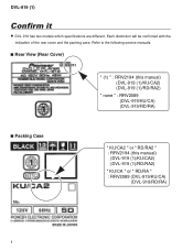
DVL-919 (1) Confirm it ¶ DVL-919 has two models which specifications are different. Refer to the following service manuals. 7 Rear View (Rear Cover) " (1) " : RRV2194 (this manual) (DVL-919 (1)/KU/CA2) (DVL-919 (1)/RD/RA2) " none " : RRV2089 (DVL-919/KU/CA) (DVL-919/RD/RA) 7 Packing Case " KU/CA2 " or " RD/RA2 " : RRV2194 (this manual) (DVL-919 (1)/KU/CA2) (DVL-919 (1)/RD/RA2) " KU/CA " or " RD/RA " : RRV2089 (DVL-919/KU/CA) (DVL-919/RD/RA) 8 Each distinction will be confirmed with the indication of the rear cover and the packing case.
DVL-919 (1) Confirm it ¶ DVL-919 has two models which specifications are different. Refer to the following service manuals. 7 Rear View (Rear Cover) " (1) " : RRV2194 (this manual) (DVL-919 (1)/KU/CA2) (DVL-919 (1)/RD/RA2) " none " : RRV2089 (DVL-919/KU/CA) (DVL-919/RD/RA) 7 Packing Case " KU/CA2 " or " RD/RA2 " : RRV2194 (this manual) (DVL-919 (1)/KU/CA2) (DVL-919 (1)/RD/RA2) " KU/CA " or " RD/RA " : RRV2089 (DVL-919/KU/CA) (DVL-919/RD/RA) 8 Each distinction will be confirmed with the indication of the rear cover and the packing case.


