Owner's Manual
Page 4
... 70 Connecting without the rubber bush - Method A - Contents Audio Adjustment 61 Switching to the Audio Adjustment Screen .... 61 - Installation without Audio Unit (DEQ-P9 71 Connecting with the rubber bush - Fitting horizontally - Method B Specifications 83 3 Removing the Unit DIN Rear-mount 77 - ...Selecting the AUX Source - Bass/Treble Adjustment - Installation with Audio Unit (DEQ-P9 73 Installation 75 DIN Front/Rear-mount 75 DIN Front-mount 75 - Installation using the screw holes on the side of the unit About the fixing screws for ...
... 70 Connecting without the rubber bush - Method A - Contents Audio Adjustment 61 Switching to the Audio Adjustment Screen .... 61 - Installation without Audio Unit (DEQ-P9 71 Connecting with the rubber bush - Fitting horizontally - Method B Specifications 83 3 Removing the Unit DIN Rear-mount 77 - ...Selecting the AUX Source - Bass/Treble Adjustment - Installation with Audio Unit (DEQ-P9 73 Installation 75 DIN Front/Rear-mount 75 DIN Front-mount 75 - Installation using the screw holes on the side of the unit About the fixing screws for ...
Owner's Manual
Page 9
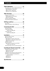
... the supplied batteries. • Do not mix new and used batteries. • In the event of battery leakage, wipe the remote controller completely clean and install new batteries. • When disposing of used batteries, please comply with a remote controller.
... the supplied batteries. • Do not mix new and used batteries. • In the event of battery leakage, wipe the remote controller completely clean and install new batteries. • When disposing of used batteries, please comply with a remote controller.
Owner's Manual
Page 11
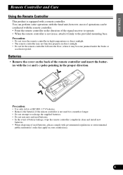
... conditions: When using this manual handy as a reference for operating procedures and precautions. • Always keep the volume low enough for the first time after installation. When strange (incorrect) messages appear on the display. • To reset the microprocessor, press the RESET button on the head unit with a pen tip or...
... conditions: When using this manual handy as a reference for operating procedures and precautions. • Always keep the volume low enough for the first time after installation. When strange (incorrect) messages appear on the display. • To reset the microprocessor, press the RESET button on the head unit with a pen tip or...
Owner's Manual
Page 70
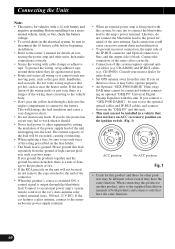
... of the unit and tapping into the engine compartment to connect to the owner's manual for other products may fail to the supplied Installation manuals of this system requires optional optical cables (e.g. Do not route wiring in a vehicle that does not have an ACC (accessory)... same function. 69 When connecting this unit. If you connect a "GEX-P900 DAB(II)", be connected without connecting an optional "DEQ-P9" Universal Digital Preamp Equalizer with a 12-volt battery and negative grounding. Consult your nearest dealer for vehicles with this product to another product...
... of the unit and tapping into the engine compartment to connect to the owner's manual for other products may fail to the supplied Installation manuals of this system requires optional optical cables (e.g. Do not route wiring in a vehicle that does not have an ACC (accessory)... same function. 69 When connecting this unit. If you connect a "GEX-P900 DAB(II)", be connected without connecting an optional "DEQ-P9" Universal Digital Preamp Equalizer with a 12-volt battery and negative grounding. Consult your nearest dealer for vehicles with this product to another product...
Owner's Manual
Page 76
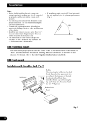
...53 Holder After inserting the holder into the dashboard, then select the appropriate tabs according to the thickness of unit chassis). Installation Note: • Before finally installing the unit, connect the wiring temporarily, making sure it is all connected up properly, and the unit and the system work...driver's way and cannot injure the passenger if there is a sudden stop, like an emergency stop. • The semiconductor laser will be properly installed either from horizontal, the unit might not give its optimum performance. (Fig. 6) 60° Fig. 6 DIN Front/Rear-mount This unit...
...53 Holder After inserting the holder into the dashboard, then select the appropriate tabs according to the thickness of unit chassis). Installation Note: • Before finally installing the unit, connect the wiring temporarily, making sure it is all connected up properly, and the unit and the system work...driver's way and cannot injure the passenger if there is a sudden stop, like an emergency stop. • The semiconductor laser will be properly installed either from horizontal, the unit might not give its optimum performance. (Fig. 6) 60° Fig. 6 DIN Front/Rear-mount This unit...
Owner's Manual
Page 77
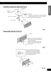
... (5 mm) Screw Strap Be sure to use the strap to secure the back of the unit, pull the unit out. ENGLISH ESPAÑOL DEUTSCH Installation without the rubber bush (Fig. 8) Nut (5 mm) Drill a 5.5 - 6.0 mm diameter hole.
... (5 mm) Screw Strap Be sure to use the strap to secure the back of the unit, pull the unit out. ENGLISH ESPAÑOL DEUTSCH Installation without the rubber bush (Fig. 8) Nut (5 mm) Drill a 5.5 - 6.0 mm diameter hole.
Owner's Manual
Page 78
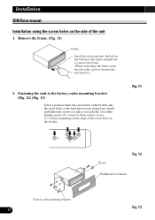
... of the frame and pull out to remove the frame. (When reattaching the frame, point the side with a groove downwards and attach it.) 2. Installation DIN Rear-mount Installation using the screw holes on each side. Fig. 11 Factory radio mounting br1a2cket 77 1S1crew Fig. 12 1D3ashboard or Console Fig. 13 Use either...
... of the frame and pull out to remove the frame. (When reattaching the frame, point the side with a groove downwards and attach it.) 2. Installation DIN Rear-mount Installation using the screw holes on each side. Fig. 11 Factory radio mounting br1a2cket 77 1S1crew Fig. 12 1D3ashboard or Console Fig. 13 Use either...
Owner's Manual
Page 80
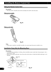
...8226; Before using double-sided tape, clean off any dirt on the surface to which the double-sided tape is installed vertically, you can not open the remote controller cover. Installing the Remote Control Unit Fitting the Remote Control Unit Precaution: • Press the remote controller unit onto the mounting base... remote control unit to be attached. Mounting Base Double-sided tape Not used Used Passenger 79 Fig. 17 Installation Using Only the Mounting Base Precaution: • To avoid it clicks into place. Fitting horizontally Fitting vertically Fig. 15 Fig. 16 Note: •...
...8226; Before using double-sided tape, clean off any dirt on the surface to which the double-sided tape is installed vertically, you can not open the remote controller cover. Installing the Remote Control Unit Fitting the Remote Control Unit Precaution: • Press the remote controller unit onto the mounting base... remote control unit to be attached. Mounting Base Double-sided tape Not used Used Passenger 79 Fig. 17 Installation Using Only the Mounting Base Precaution: • To avoid it clicks into place. Fitting horizontally Fitting vertically Fig. 15 Fig. 16 Note: •...
Owner's Manual
Page 81
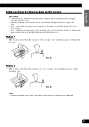
... the console is adjusted. 80 FRANÇAIS ITALIANO NEDERLANDS Fig. 18 Method B This example is for the mounting base. Fig. 19 Note: • Install the mounting base in such a way that the screws will not hit the seat when the seat is not wide enough to the passenger's side... - ating systems (such as the fuel line, brake lines, electrical wiring, etc.). ENGLISH ESPAÑOL DEUTSCH Installation Using the Mounting Base and the Bracket Precaution: • To avoid it will not interfere with any dirt on the surface to which the double...
... the console is adjusted. 80 FRANÇAIS ITALIANO NEDERLANDS Fig. 18 Method B This example is for the mounting base. Fig. 19 Note: • Install the mounting base in such a way that the screws will not hit the seat when the seat is not wide enough to the passenger's side... - ating systems (such as the fuel line, brake lines, electrical wiring, etc.). ENGLISH ESPAÑOL DEUTSCH Installation Using the Mounting Base and the Bracket Precaution: • To avoid it will not interfere with any dirt on the surface to which the double...
Owner's Manual
Page 82
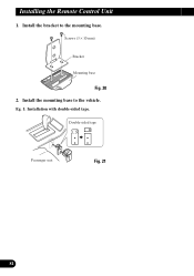
Install the bracket to the vehicle. Screws (3 × 10 mm) Bracket Mounting base Fig. 20 2. Install the mounting base to the mounting base. Eg. 1: Installation with double-sided tape. Double-sided tape Passenger seat Fig. 21 81 Installing the Remote Control Unit 1.
Install the bracket to the vehicle. Screws (3 × 10 mm) Bracket Mounting base Fig. 20 2. Install the mounting base to the mounting base. Eg. 1: Installation with double-sided tape. Double-sided tape Passenger seat Fig. 21 81 Installing the Remote Control Unit 1.
Owner's Manual
Page 83
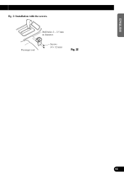
Drill holes 2 - 2.5 mm in diameter. Passenger seat Screws (4 × 12 mm) Fig. 22 ESPAÑOL DEUTSCH FRANÇAIS ITALIANO NEDERLANDS 82 ENGLISH Eg. 2: Installation with the screws.
Drill holes 2 - 2.5 mm in diameter. Passenger seat Screws (4 × 12 mm) Fig. 22 ESPAÑOL DEUTSCH FRANÇAIS ITALIANO NEDERLANDS 82 ENGLISH Eg. 2: Installation with the screws.


