
Owner's Manual
Page 2
... 7 About the demo modes 8 About basic displays 8 Remote controller and care 9 Using the steering remote controller 10 Detaching and replacing the front panel .......... 11 Basic Operation 12 Turning a source on or off 12 SOFT KEY operation 12 Key guidance indicator 14 Tuner 15 Display and indicators 15 Basic operation 15 Storing and recalling broadcast stations 15 Tuner function menu 16 Storing the strongest broadcast stations............16 Selecting stations from the preset channel list 16 Tuning in strong...
... 7 About the demo modes 8 About basic displays 8 Remote controller and care 9 Using the steering remote controller 10 Detaching and replacing the front panel .......... 11 Basic Operation 12 Turning a source on or off 12 SOFT KEY operation 12 Key guidance indicator 14 Tuner 15 Display and indicators 15 Basic operation 15 Storing and recalling broadcast stations 15 Tuner function menu 16 Storing the strongest broadcast stations............16 Selecting stations from the preset channel list 16 Tuning in strong...

Owner's Manual
Page 3
... Tuner 37 Display and indicators 37 Basic operation 37 Storing and recalling broadcast stations .......... 37 Changing band 38 TV tuner function menu 38 Selecting channels from the preset channel list 38 Audio Adjustments 39 Operation modes 39 3-way network mode 39 Standard mode 39 Extra functions 40 Audio menu 40 Using position selector 40 Using time alignment 41 Using balance adjustment 41 Adjusting time alignment 41 About the network function 42 Using subwoofer output 45 Using the high pass filter 45 Using the auto-equalizer 46 Recalling equalizer...
... Tuner 37 Display and indicators 37 Basic operation 37 Storing and recalling broadcast stations .......... 37 Changing band 38 TV tuner function menu 38 Selecting channels from the preset channel list 38 Audio Adjustments 39 Operation modes 39 3-way network mode 39 Standard mode 39 Extra functions 40 Audio menu 40 Using position selector 40 Using time alignment 41 Using balance adjustment 41 Adjusting time alignment 41 About the network function 42 Using subwoofer output 45 Using the high pass filter 45 Using the auto-equalizer 46 Recalling equalizer...

Owner's Manual
Page 6
... preset memory will be erased and must be reprogrammed. 5 You can perform the same operations with ISO9660 Level 1/Level 2 standards). (See page 62.) About this product The tuner frequencies on CD-ROM/CD-R/CD-RW discs (recordings complying with the steering remote controller. WARNING: • Do not use the unit in Standard mode when a speaker system for 3-way network mode is connected to be audible. • Protect...
... preset memory will be erased and must be reprogrammed. 5 You can perform the same operations with ISO9660 Level 1/Level 2 standards). (See page 62.) About this product The tuner frequencies on CD-ROM/CD-R/CD-RW discs (recordings complying with the steering remote controller. WARNING: • Do not use the unit in Standard mode when a speaker system for 3-way network mode is connected to be audible. • Protect...
Owner's Manual
Page 8
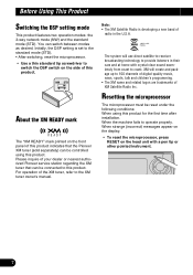
... machine fails to the XM tuner owner's manual. Please inquire of your dealer or nearest authorized Pioneer service station regarding the XM tuner that the Pioneer XM tuner (sold separately) can be connected to switch the DSP switch on the side of this product. Note: • The XM Satellite Radio is set to the standard mode (STD). • After switching, reset the microprocessor. • Use a thin standard tip screwdriver...
... machine fails to the XM tuner owner's manual. Please inquire of your dealer or nearest authorized Pioneer service station regarding the XM tuner that the Pioneer XM tuner (sold separately) can be connected to switch the DSP switch on the side of this product. Note: • The XM Satellite Radio is set to the standard mode (STD). • After switching, reset the microprocessor. • Use a thin standard tip screwdriver...

Owner's Manual
Page 10
... (+) and (-) poles pointing in the proper direction. Before Using This Product Remote controller and care Installing the lithium battery • Remove the cover on the back of the steering remote controller and insert the battery with its (+) and (-) poles facing in the proper directions. Precaution: • Replace the battery with a CR2032 lithium battery. • Replace the battery in a fire. • Use a CR2032 (3 V) lithium battery only. CAUTION: • Do not...
... (+) and (-) poles pointing in the proper direction. Before Using This Product Remote controller and care Installing the lithium battery • Remove the cover on the back of the steering remote controller and insert the battery with its (+) and (-) poles facing in the proper directions. Precaution: • Replace the battery with a CR2032 lithium battery. • Replace the battery in a fire. • Use a CR2032 (3 V) lithium battery only. CAUTION: • Do not...

Owner's Manual
Page 11
... remote controller will not function properly. When operating the remote controller, however, switch through the modes as this might prevent the driver from the operation of being involved in CD player function menu" on the head unit. If you continue to use the multi-function buttons to avoid the risk of the FUNC button and the AUDIO button on page 18. When operating the head unit, use the FUNC button and the AUDIO button to select the appropriate menu, then use...
... remote controller will not function properly. When operating the remote controller, however, switch through the modes as this might prevent the driver from the operation of being involved in CD player function menu" on the head unit. If you continue to use the multi-function buttons to avoid the risk of the FUNC button and the AUDIO button on page 18. When operating the head unit, use the FUNC button and the AUDIO button to select the appropriate menu, then use...
Owner's Manual
Page 13
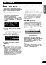
... to turn the source off . Important In this manual, for operations using the multifunction buttons the function displayed is displayed whether you press VOLUME, it extends outward so that the function of a button changes as a source, enables control of basic functions by the buttons change : * When no product corresponding to the source is connected to this product. * No disc is set in this product. * No magazine is set in the multi-CD player. * AUX (auxiliary setting) is set...
... to turn the source off . Important In this manual, for operations using the multifunction buttons the function displayed is displayed whether you press VOLUME, it extends outward so that the function of a button changes as a source, enables control of basic functions by the buttons change : * When no product corresponding to the source is connected to this product. * No disc is set in this product. * No magazine is set in the multi-CD player. * AUX (auxiliary setting) is set...

Owner's Manual
Page 29
... numbers and symbols mode. 4. That selection will begin to play a disc you input up to 100 CD titles up to 10 letters long (with accents (e.g Press 012 to switch to switch between the following display. CD player is displayed. 1. The light illuminates. Press ABC repeatedly to select and play the desired disc title. • "No D.Title" is displayed for playback. "12". 3. Note: • You can also use...
... numbers and symbols mode. 4. That selection will begin to play a disc you input up to 100 CD titles up to 10 letters long (with accents (e.g Press 012 to switch to switch between the following display. CD player is displayed. 1. The light illuminates. Press ABC repeatedly to select and play the desired disc title. • "No D.Title" is displayed for playback. "12". 3. Note: • You can also use...

Owner's Manual
Page 32
... The currently received service has a secondary service component. For details of DAB tuner-specific operation/features, see your DAB tuner's manual. • This product does not have the language filter function. • With this product to control a DAB tuner, which is possible. Turn VOLUME to select an ensemble. 31 To retract VOLUME, press it becomes easier to turn. DAB Tuner The following explains how to use this product...
... The currently received service has a secondary service component. For details of DAB tuner-specific operation/features, see your DAB tuner's manual. • This product does not have the language filter function. • With this product to control a DAB tuner, which is possible. Turn VOLUME to select an ensemble. 31 To retract VOLUME, press it becomes easier to turn. DAB Tuner The following explains how to use this product...
Owner's Manual
Page 40
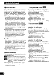
... following settings/adjustments in your audio system to recreate realistic sound fields in order, you can create a finely-tuned sound field effortlessly. • Using position selector (POSI) • Using time alignment (T.AL1) • Using balance adjustment (F/B) • Adjusting time alignment (T.AL2) • Using subwoofer output (SW1) • Adjusting subwoofer settings (SW2) • Setting the high pass filter for front speakers (HPF F) • Setting the high pass filter for rear speakers (HPF R) • Creating the auto-equalizer curve...
... following settings/adjustments in your audio system to recreate realistic sound fields in order, you can create a finely-tuned sound field effortlessly. • Using position selector (POSI) • Using time alignment (T.AL1) • Using balance adjustment (F/B) • Adjusting time alignment (T.AL2) • Using subwoofer output (SW1) • Adjusting subwoofer settings (SW2) • Setting the high pass filter for front speakers (HPF F) • Setting the high pass filter for rear speakers (HPF R) • Creating the auto-equalizer curve...

Owner's Manual
Page 42
... an adjusted time alignment that you can select a fader/balance setting that provides an ideal listening environment in "Custom" when "STD" mode has been selected. 1. Press the corresponding button to select a unit of distance Centimeter Inch 41 "FADER R25" is displayed as the front/rear speaker balance moves from front to rear. • "FADER FR00" is displayed as the left/right speaker balance moves from left /right speaker balance. Press AUDIO...
... an adjusted time alignment that you can select a fader/balance setting that provides an ideal listening environment in "Custom" when "STD" mode has been selected. 1. Press the corresponding button to select a unit of distance Centimeter Inch 41 "FADER R25" is displayed as the front/rear speaker balance moves from front to rear. • "FADER FR00" is displayed as the left/right speaker balance moves from left /right speaker balance. Press AUDIO...

Owner's Manual
Page 46
... to select the subwoofer output mode. 2. "SUB. Press 3 to turn the subwoofer output on , you do not want low sound to play from the front or rear speakers. Each press of 5 or ∞ increases or decreases the level of 2 or 3 selects frequencies in the display. • Press HPF R again to select the high pass filter mode. 2. Note: • "SW2" is not displayed when the subwoofer output is connected and you can adjust the...
... to select the subwoofer output mode. 2. "SUB. Press 3 to turn the subwoofer output on , you do not want low sound to play from the front or rear speakers. Each press of 5 or ∞ increases or decreases the level of 2 or 3 selects frequencies in the display. • Press HPF R again to select the high pass filter mode. 2. Note: • "SW2" is not displayed when the subwoofer output is connected and you can adjust the...

Owner's Manual
Page 47
... to turn the auto-equalizer on . Press EEQ to switch to select the graphic equalizer mode. 2. Note: • You can also use 2 and 3 to select the desired equaliz- Press AUDIO and then press EQ1 to the easy equalizer mode. 2. Note: • The actual range of 5 or ∞ increases or decreases the equalizer curve respectively. • "+6" - er curve. Adjusting equalizer curves The factory supplied equalizer curves, with all frequencies set equalizer...
... to turn the auto-equalizer on . Press EEQ to switch to select the graphic equalizer mode. 2. Note: • You can also use 2 and 3 to select the desired equaliz- Press AUDIO and then press EQ1 to the easy equalizer mode. 2. Note: • The actual range of 5 or ∞ increases or decreases the equalizer curve respectively. • "+6" - er curve. Adjusting equalizer curves The factory supplied equalizer curves, with all frequencies set equalizer...

Owner's Manual
Page 48
... make adjustments when the "CUSTOM2" curve is a trademark of each source. (The built-in CD and the multi-CD players are listening to switch the octaver setting. Each press of phase compensation and highrange boost for each band. • A separate "CUSTOM1" curve can then select another band and adjust the level. 5. Using octaver and BBER sound Octaver makes the bass sound louder. Refer to adjust. Audio Adjustments Adjusting...
... make adjustments when the "CUSTOM2" curve is a trademark of each source. (The built-in CD and the multi-CD players are listening to switch the octaver setting. Each press of phase compensation and highrange boost for each band. • A separate "CUSTOM1" curve can then select another band and adjust the level. 5. Using octaver and BBER sound Octaver makes the bass sound louder. Refer to adjust. Audio Adjustments Adjusting...

Owner's Manual
Page 51
...based on battery power. When speakers are incorrectly connected. (e.g., When a rear speaker is placed in a place that information. When a speaker is connected to the standard position. • Auto-equalizing changes the audio settings as possible, with input level control, auto-equalizing may prevent correct auto-equalizing. Carrying out auto-equalizing 1. Set the power amp's input level to a power amp delivering output higher than the measurement tone (surrounding sounds, engine sound, telephones ringing etc.) may damage the speakers. The fader/balance settings return...
...based on battery power. When speakers are incorrectly connected. (e.g., When a rear speaker is placed in a place that information. When a speaker is connected to the standard position. • Auto-equalizing changes the audio settings as possible, with input level control, auto-equalizing may prevent correct auto-equalizing. Carrying out auto-equalizing 1. Set the power amp's input level to a power amp delivering output higher than the measurement tone (surrounding sounds, engine sound, telephones ringing etc.) may damage the speakers. The fader/balance settings return...

Owner's Manual
Page 52
... the autoequalizer measurement mode. If the car's air conditioner or heater is displayed. (Refer to "Understanding auto-equalizing error messages" on , turn it off . 6. Press A.EQ to turn the source on this product is displayed. Store the microphone carefully in about four minutes. • To cancel auto-equalizing part way through, press any other safe place. Audio Adjustments 2. Plug the microphone into the microphone input jack on...
... the autoequalizer measurement mode. If the car's air conditioner or heater is displayed. (Refer to "Understanding auto-equalizing error messages" on , turn it off . 6. Press A.EQ to turn the source on this product is displayed. Store the microphone carefully in about four minutes. • To cancel auto-equalizing part way through, press any other safe place. Audio Adjustments 2. Plug the microphone into the microphone input jack on...
Owner's Manual
Page 62
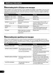
... possible using the autoequalizer, an error message may appear on the display. Plug the supplied microphone securely into the jack. Set the microphone correctly. ERROR CHECK SYSTEM The surrounding noise level is not connected. The auto-equalizing function does not work in CD player error messages When problems occur during CD play, an error message may appear on the display. Replace disc. Turn the ignition ON and OFF, or switch to a different source...
... possible using the autoequalizer, an error message may appear on the display. Plug the supplied microphone securely into the jack. Set the microphone correctly. ERROR CHECK SYSTEM The surrounding noise level is not connected. The auto-equalizing function does not work in CD player error messages When problems occur during CD play, an error message may appear on the display. Replace disc. Turn the ignition ON and OFF, or switch to a different source...
Other Manual
Page 1
... speaker ≠ Right + Rear speaker ≠ Orange/white To lighting switch terminal. Likewise, do not connect anything to the owner's manual for standard mode Antenna jack 23 cm (7/8 inch) 15 cm (5/8 inch) DSP switch Switch the DSP switch as near the heater outlet. If you do not remove the caps attached to the end of the connector. • Speakers connected to the battery. Before installing it via the Audio Mute lead...
... speaker ≠ Right + Rear speaker ≠ Orange/white To lighting switch terminal. Likewise, do not connect anything to the owner's manual for standard mode Antenna jack 23 cm (7/8 inch) 15 cm (5/8 inch) DSP switch Switch the DSP switch as near the heater outlet. If you do not remove the caps attached to the end of the connector. • Speakers connected to the battery. Before installing it via the Audio Mute lead...

Other Manual
Page 2
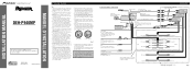
... as illustration below. Connecting the Units Connection diagram for 3-way network mode Antenna jack 23 cm (7/8 inch) 15 cm (5/8 inch) DSP switch Switch the DSP switch as possible using a different amp (sold separately) 15 cm (5/8 inch) IP-BUS cable High range output (HIGH/FRONT OUTPUT) Blue/white To system control terminal of the power amp or Auto-antenna relay control terminal (max. 300 mA 12 V DC). DIN Front-mount Installation with the rubber bush...
... as illustration below. Connecting the Units Connection diagram for 3-way network mode Antenna jack 23 cm (7/8 inch) 15 cm (5/8 inch) DSP switch Switch the DSP switch as possible using a different amp (sold separately) 15 cm (5/8 inch) IP-BUS cable High range output (HIGH/FRONT OUTPUT) Blue/white To system control terminal of the power amp or Auto-antenna relay control terminal (max. 300 mA 12 V DC). DIN Front-mount Installation with the rubber bush...
Other Manual
Page 3
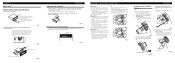
... unit to the factory radio mounting bracket. (Fig. 10) (Fig. 11) Select a position where the screw holes of the bracket and the screw holes of signals from the unit to the car stereo. Use either binding screws (5 × 6 mm) or flush surface screws (5 × 6 mm), depending on each side. Fixing screw Fig. 13 Installing the Steering Remote Control Unit WARNING • Avoid installing this unit...
... unit to the factory radio mounting bracket. (Fig. 10) (Fig. 11) Select a position where the screw holes of the bracket and the screw holes of signals from the unit to the car stereo. Use either binding screws (5 × 6 mm) or flush surface screws (5 × 6 mm), depending on each side. Fixing screw Fig. 13 Installing the Steering Remote Control Unit WARNING • Avoid installing this unit...


