

Operation Manual
Page 71
... lead) to work when it cannot touch any leads. CAUTION: The default output settings values for other units, then make connections correctly. • Secure the wiring with the output settings for several hours. (Fig.1) F ACC O F O OF OF N STAR N STAR T T ACC position No ACC position Fig. ...1 • The black lead is employed, never wire so the speaker leads are directly grounded or the left and right ≠ speaker leads are not insulated. • To prevent incorrect connection, the input...
... lead) to work when it cannot touch any leads. CAUTION: The default output settings values for other units, then make connections correctly. • Secure the wiring with the output settings for several hours. (Fig.1) F ACC O F O OF OF N STAR N STAR T T ACC position No ACC position Fig. ...1 • The black lead is employed, never wire so the speaker leads are directly grounded or the left and right ≠ speaker leads are not insulated. • To prevent incorrect connection, the input...

Operation Manual
Page 72
... system, do not connect anything to the speaker leads that are not connected to Fig. 5. 15 cm (5-7/8 in.) Jack for Wired Remote Control Please see the Instruction Manual for the Wired Remote Control (sold separately) Yellow/black If you use a cellular telephone, connect it via the Audio Mute lead on the cellular...
... system, do not connect anything to the speaker leads that are not connected to Fig. 5. 15 cm (5-7/8 in.) Jack for Wired Remote Control Please see the Instruction Manual for the Wired Remote Control (sold separately) Yellow/black If you use a cellular telephone, connect it via the Audio Mute lead on the cellular...

Operation Manual
Page 73
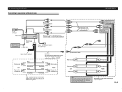
... leads that are not connected to RD-221 owner's manual. Orange/white To lighting switch terminal. Fig. 4 Yellow To separately sold power supply wiring kit (RD-221). Red To electric terminal controlled by ignition switch (12 V DC) ON/OFF. Fuse resistor Fuse holder Fuse holder Front speaker... Left Rear speaker or Subwoofer Jack for Wired Remote Control Please see the Instruction Manual for the vehicle is less than 10A. White + ≠ White/black + Green ≠ Green/black ...
... leads that are not connected to RD-221 owner's manual. Orange/white To lighting switch terminal. Fig. 4 Yellow To separately sold power supply wiring kit (RD-221). Red To electric terminal controlled by ignition switch (12 V DC) ON/OFF. Fuse resistor Fuse holder Fuse holder Front speaker... Left Rear speaker or Subwoofer Jack for Wired Remote Control Please see the Instruction Manual for the vehicle is less than 10A. White + ≠ White/black + Green ≠ Green/black ...
Operation Manual
Page 74
... (Blue) IP-BUS cable Front output (FRONT OUTPUT) Rear output (REAR OUTPUT) Subwoofer output or Non Fading Output (SUBWOOFER or NON-FADING OUTPUT) Jack for Wired Remote Control 15 cm (5-7/8 in.) Connecting cords with RCA pin plugs (sold separately) Power amp (sold separately) Power amp (sold separately) Power amp (sold separately...
... (Blue) IP-BUS cable Front output (FRONT OUTPUT) Rear output (REAR OUTPUT) Subwoofer output or Non Fading Output (SUBWOOFER or NON-FADING OUTPUT) Jack for Wired Remote Control 15 cm (5-7/8 in.) Connecting cords with RCA pin plugs (sold separately) Power amp (sold separately) Power amp (sold separately) Power amp (sold separately...

Operation Manual
Page 75
Installation Note: • Before finally installing the unit, connect the wiring temporarily, making sure it is a sudden stop, like an emergency stop. • The semiconductor laser will be bent by hand to the desired angle. DIN ...
Installation Note: • Before finally installing the unit, connect the wiring temporarily, making sure it is a sudden stop, like an emergency stop. • The semiconductor laser will be bent by hand to the desired angle. DIN ...


