Operation Manual
Page 62
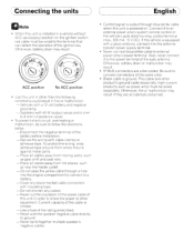
... terminal of the ignition key. Place all cables away from hot places. If the vehicle is ground. Other·wise. Never wire the speaker negative cable directly to a battery. -Cover any cables. - battery drain or malfunction may result. high-current products ... with a glass antenna. ( Connecting the units ) ( English) aNote • When this unit is powered on the ignition switch. be wired separately. Never band together multiple speaker's negative cables. • Control signal is output through a hole into the engine compartment to connect to ground...
... terminal of the ignition key. Place all cables away from hot places. If the vehicle is ground. Other·wise. Never wire the speaker negative cable directly to a battery. -Cover any cables. - battery drain or malfunction may result. high-current products ... with a glass antenna. ( Connecting the units ) ( English) aNote • When this unit is powered on the ignition switch. be wired separately. Never band together multiple speaker's negative cables. • Control signal is output through a hole into the engine compartment to connect to ground...
Operation Manual
Page 65
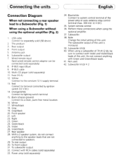
.... Left 22. CConnecting the units ) ( English] Connection Diagram When not connecting a rear speaker lead to the constant 12 V supply terminal. 13. Rear output 4. Wired remote input Hard-wired remote control adaptor can be sure to connect with Violet and Violet/black leads of the power amp or auto-antenna relay control terminal...
.... Left 22. CConnecting the units ) ( English] Connection Diagram When not connecting a rear speaker lead to the constant 12 V supply terminal. 13. Rear output 4. Wired remote input Hard-wired remote control adaptor can be sure to connect with Violet and Violet/black leads of the power amp or auto-antenna relay control terminal...

Operation Manual
Page 66
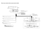
... a clean. Rear speaker This P~Oduct 20 cm (7-7/8 in.) 1 29. System remote control L , 34. Blue/white I I Connect to a subwoofer 7-~ + I ~o ~I 1. Antenna Jac / 7SW:f= °i~::Jc;-+--- 7 Wired remote input Hard-wired rem.ote control adaptor can '" be connected (sold USB device. 3. When not connecting a rear speaker lea to system control terminal of the power I amp...
... a clean. Rear speaker This P~Oduct 20 cm (7-7/8 in.) 1 29. System remote control L , 34. Blue/white I I Connect to a subwoofer 7-~ + I ~o ~I 1. Antenna Jac / 7SW:f= °i~::Jc;-+--- 7 Wired remote input Hard-wired rem.ote control adaptor can '" be connected (sold USB device. 3. When not connecting a rear speaker lea to system control terminal of the power I amp...
Operation Manual
Page 67
... to connect with Green and Green/black leads j r:::-i'=:I ',0_0' :7 --' O:cYO, 5. be connected (sold USB device. 20cm (7-7/8 in.) 3 Rear outi~: ~' 2" This P~Oduct , 4 Front output --'--'I 7 Wired remote Input Hard-wired remote control adaptor can be sure to terminal controlled by ignition switch (12 V DC). USB cable Connect to separately sold separately). 6 Subwoofer output 11...
... to connect with Green and Green/black leads j r:::-i'=:I ',0_0' :7 --' O:cYO, 5. be connected (sold USB device. 20cm (7-7/8 in.) 3 Rear outi~: ~' 2" This P~Oduct , 4 Front output --'--'I 7 Wired remote Input Hard-wired remote control adaptor can be sure to terminal controlled by ignition switch (12 V DC). USB cable Connect to separately sold separately). 6 Subwoofer output 11...


