Operation Manual
Page 62
...) position on , Connect it to the antenna booster power supply terminal. • Never connect blue/white cable to an external power amp's system remote control or the vehicle's auto,antenna relay control ter'minal (max. 300 mA. 12 V DC). Other·wise. overheating or malfunction. such ... may result if they lie against metal parts, - ACC position No ACC position • Use this unit in fire or malfunction, - Never wire the speaker negative cable directly to a battery. -Cover any cables. - Place all cables away from moving parts. Do not shorten any disconnected cable...
...) position on , Connect it to the antenna booster power supply terminal. • Never connect blue/white cable to an external power amp's system remote control or the vehicle's auto,antenna relay control ter'minal (max. 300 mA. 12 V DC). Other·wise. overheating or malfunction. such ... may result if they lie against metal parts, - ACC position No ACC position • Use this unit in fire or malfunction, - Never wire the speaker negative cable directly to a battery. -Cover any cables. - Place all cables away from moving parts. Do not shorten any disconnected cable...
Operation Manual
Page 65
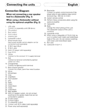
.... Right 23. Green/black 25. When using a subwoofer of the power amp or auto-antenna relay control terminal (max. 300 mA 12 V DC). 35. Wired remote input Hard-wired remote control adaptor can be sure to connect with RCA cables (sold separately) 33. IP-BUS input (Blue) 9. White 17. Gray/black 20. Violet 26...
.... Right 23. Green/black 25. When using a subwoofer of the power amp or auto-antenna relay control terminal (max. 300 mA 12 V DC). 35. Wired remote input Hard-wired remote control adaptor can be sure to connect with RCA cables (sold separately) 33. IP-BUS input (Blue) 9. White 17. Gray/black 20. Violet 26...

Operation Manual
Page 66
Rear outF7:~:9; 2. To subwoofer output ~-'/-----4 d~ l:i..:...:o~~""""'1Ir..iI 12. Green 25. Green/black 26. System remote control L , 34. USB cable Connect to a clean. Subwoofer output 8 IP-BUS Input (Blue) 11. Fuse (10 ... 18. Front speaker 27. Front output ~l."·9 i$ . paint-free metal location. 1 1 I the optional amplifier. Antenna Jac / 7SW:f= °i~::Jc;-+--- 7 Wired remote input Hard-wired rem.ote control adaptor can '" be connected (sold USB device. 3. Red Connect to speakers. 35. Gray I ~ : I - 1 37.Subwoofer 20. Front ...
Rear outF7:~:9; 2. To subwoofer output ~-'/-----4 d~ l:i..:...:o~~""""'1Ir..iI 12. Green 25. Green/black 26. System remote control L , 34. USB cable Connect to a clean. Subwoofer output 8 IP-BUS Input (Blue) 11. Fuse (10 ... 18. Front speaker 27. Front output ~l."·9 i$ . paint-free metal location. 1 1 I the optional amplifier. Antenna Jac / 7SW:f= °i~::Jc;-+--- 7 Wired remote input Hard-wired rem.ote control adaptor can '" be connected (sold USB device. 3. Red Connect to speakers. 35. Gray I ~ : I - 1 37.Subwoofer 20. Front ...
Operation Manual
Page 67
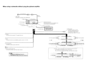
.... 13. Blue/white / Connect to connect with Green and Green/black leads be connected (sold USB device. 20cm (7-7/8 in.) 3 Rear outi~: ~' 2" This P~Oduct , 4 Front output --'--'I 7 Wired remote Input Hard-wired remote control adaptor can be sure to system control terminal of this unit. Antenna Jack.----l: t:J ~ c 7- -
.... 13. Blue/white / Connect to connect with Green and Green/black leads be connected (sold USB device. 20cm (7-7/8 in.) 3 Rear outi~: ~' 2" This P~Oduct , 4 Front output --'--'I 7 Wired remote Input Hard-wired remote control adaptor can be sure to system control terminal of this unit. Antenna Jack.----l: t:J ~ c 7- -


