Other Manual
Page 2
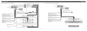
...) Blue/white To system control terminal of this unit is monaural. Orange/white To lighting switch terminal. Yellow To terminal always supplied with power regardless of any connections. Orange/white To lighting switch terminal. Fig. 3 Connecting the Units 7 When not connecting a rear speaker lead ... it via the Audio Mute lead on the cellular telephone. Red To electric terminal controlled by ignition switch (12 V DC) ON/OFF. Connecting cords with RCA pin plugs (sold separately) IP-BUS input (Blue) IP-BUS cable Multi-CD player (sold separately) + Front speaker ≠ ...
...) Blue/white To system control terminal of this unit is monaural. Orange/white To lighting switch terminal. Yellow To terminal always supplied with power regardless of any connections. Orange/white To lighting switch terminal. Fig. 3 Connecting the Units 7 When not connecting a rear speaker lead ... it via the Audio Mute lead on the cellular telephone. Red To electric terminal controlled by ignition switch (12 V DC) ON/OFF. Connecting cords with RCA pin plugs (sold separately) IP-BUS input (Blue) IP-BUS cable Multi-CD player (sold separately) + Front speaker ≠ ...


