Service Manual
Page 1
... 6. P.O.Box 1760, Long Beach, CA 90801-1760 U.S.A. CONTENTS 1. GENERAL INFORMATION 49 7.1 PARTS 49 7.1.1 IC 49 7.1.2 DISPLAY 56 7.2 DIAGNOSIS 57 7.2.1 DISASSEMBLY 57 7.2.2 TEST MODE 58 7.3 BLOCK DIAGRAM 62 8. EXPLODED VIEWS AND PARTS LIST 2 3. PCB CONNECTION DIAGRAM 28 5. SCHEMATIC DIAGRAM 12 4. Service DEH-P2000/X1N/UC Manual MULTI-CD CONTROL HIGH POWER CD PLAYER WITH FM/AM TUNER DEH-P2000 DEH-P20 X1N/UC DEH-P2050 X1N/ES,ES ORDER NO. CRT2311 X1N/UC -
... 6. P.O.Box 1760, Long Beach, CA 90801-1760 U.S.A. CONTENTS 1. GENERAL INFORMATION 49 7.1 PARTS 49 7.1.1 IC 49 7.1.2 DISPLAY 56 7.2 DIAGNOSIS 57 7.2.1 DISASSEMBLY 57 7.2.2 TEST MODE 58 7.3 BLOCK DIAGRAM 62 8. EXPLODED VIEWS AND PARTS LIST 2 3. PCB CONNECTION DIAGRAM 28 5. SCHEMATIC DIAGRAM 12 4. Service DEH-P2000/X1N/UC Manual MULTI-CD CONTROL HIGH POWER CD PLAYER WITH FM/AM TUNER DEH-P2000 DEH-P20 X1N/UC DEH-P2050 X1N/ES,ES ORDER NO. CRT2311 X1N/UC -
Service Manual
Page 2
... to turn the power off since an internal IC might be sure to "Disassembly"(CX-916 Service Manual CRT2300). you are known to do -it-yourselfer. WARNING This product contains lead in solder and certain electrical parts contain chemicals which are not qualified to properly and safely repair complex products such as those covered by a short pin). 1. DEH-P2000...
... to turn the power off since an internal IC might be sure to "Disassembly"(CX-916 Service Manual CRT2300). you are known to do -it-yourselfer. WARNING This product contains lead in solder and certain electrical parts contain chemicals which are not qualified to properly and safely repair complex products such as those covered by a short pin). 1. DEH-P2000...
Service Manual
Page 3
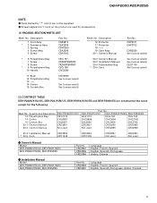
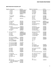
... table(2) Part No. Installation Manual Model DEH-P2000/X1N/UC, DEH-P20/X1N/UC DEH-P2050/X1N/ES, DEH-P2050/ES Part No. DEH-P20/X1N/UC DEH-P2050/X1N/ES DEH-P2050/ES CEG1173 CEG-162 CEG-162 CHG3656 CHG3659 CHG3762 CHL3656 CHL3659 CHL3762 CRD2851 CRD2855 CRD2855 Not used CRD2856 CRD2856 20-3 Installation Manual * 20-5 Card CRD2852 ARY1048 CRD2852 ARY1048 CRD2857 Not used CRD2857 Not used Part No...
... table(2) Part No. Installation Manual Model DEH-P2000/X1N/UC, DEH-P20/X1N/UC DEH-P2050/X1N/ES, DEH-P2050/ES Part No. DEH-P20/X1N/UC DEH-P2050/X1N/ES DEH-P2050/ES CEG1173 CEG-162 CEG-162 CHG3656 CHG3659 CHG3762 CHL3656 CHL3659 CHL3762 CRD2851 CRD2855 CRD2855 Not used CRD2856 CRD2856 20-3 Installation Manual * 20-5 Card CRD2852 ARY1048 CRD2852 ARY1048 CRD2857 Not used CRD2857 Not used Part No...
Service Manual
Page 9
...) CNM6006 Insulator(DEH-P2050/ES) CNM6386 18 Insulator CNM6224 19 Panel CNS5132 | 20 Tuner Amp Unit 21 Screw 22 Screw 23 Screw 24 IC(IC551) CWM6090 ASZ26P080FMC BPZ26P080FMC BSZ26P160FMC PAL005A 25 Connector(CN551) 26 Antenna Cable(CN502) 27 Clamper 28 Pin Jack(CN431) 29 Terminal(CN501) CDE5996 CDH1254 CEF1006 CKB1028 CKF1059 30 Connector(CN951) * 31 Connector(CN681) 32 Connector(CN411) 33 Connector(CN651...
...) CNM6006 Insulator(DEH-P2050/ES) CNM6386 18 Insulator CNM6224 19 Panel CNS5132 | 20 Tuner Amp Unit 21 Screw 22 Screw 23 Screw 24 IC(IC551) CWM6090 ASZ26P080FMC BPZ26P080FMC BSZ26P160FMC PAL005A 25 Connector(CN551) 26 Antenna Cable(CN502) 27 Clamper 28 Pin Jack(CN431) 29 Terminal(CN501) CDE5996 CDH1254 CEF1006 CKB1028 CKF1059 30 Connector(CN951) * 31 Connector(CN681) 32 Connector(CN411) 33 Connector(CN651...

Service Manual
Page 12
SCHEMATIC DIAGRAM 3.1 OVERALL CONNECTION DIAGRAM(GUIDE PAGE) A Note: When ordering service parts, be sure to refer to "EXPLODED VIEWS AND PARTS LIST" or "ELECTRICAL PARTS LIST". Large size A-a A-b SCH diagram A A A-a IP BUS IN 4.3V 4.3V 4.3V 4.3V A-a A-b Guide page B A-a A-b Detailed page IP BUS DRIVER 4.3V 4.3V 4.3V SO ELE 4.3V B DE C ANTENNA CABLE D A 12 1 2 3 VD REGULATOR 4 1 2 3 4 DEH-P2000,P20,P2050 3.
SCHEMATIC DIAGRAM 3.1 OVERALL CONNECTION DIAGRAM(GUIDE PAGE) A Note: When ordering service parts, be sure to refer to "EXPLODED VIEWS AND PARTS LIST" or "ELECTRICAL PARTS LIST". Large size A-a A-b SCH diagram A A A-a IP BUS IN 4.3V 4.3V 4.3V 4.3V A-a A-b Guide page B A-a A-b Detailed page IP BUS DRIVER 4.3V 4.3V 4.3V SO ELE 4.3V B DE C ANTENNA CABLE D A 12 1 2 3 VD REGULATOR 4 1 2 3 4 DEH-P2000,P20,P2050 3.

Service Manual
Page 28
PCB CONNECTION DIAGRAM 4.1 TUNER AMP UNIT A NOTE FOR PCB DIAGRAMS 1. For further information for several destination. The parts mounted on this PCB A TUNER AMP UNIT include all necessary parts for respective destinations, be sure to check with the schematic dia- gram. 2. Viewpoint of PCB diagrams CORD ASSY Connector Capacitor SIDE A B P.C.Board Chip Part SIDE B C D CN701 D A 28 1 2 3 4 1 2 3 4 DEH-P2000,P20,P2050 4.
PCB CONNECTION DIAGRAM 4.1 TUNER AMP UNIT A NOTE FOR PCB DIAGRAMS 1. For further information for several destination. The parts mounted on this PCB A TUNER AMP UNIT include all necessary parts for respective destinations, be sure to check with the schematic dia- gram. 2. Viewpoint of PCB diagrams CORD ASSY Connector Capacitor SIDE A B P.C.Board Chip Part SIDE B C D CN701 D A 28 1 2 3 4 1 2 3 4 DEH-P2000,P20,P2050 4.
Service Manual
Page 45
... RF AMP gain setting to 0 dB, and the automatic adjustment value to a strong light source when the outer casing is connected to measure the potential correctly, but the servo will malfunction and a severe shock will not load a disc. If by accident REFO comes in progress, immediately turn the power off (otherwise the actuator may occur. *During PLAY, even if the eject button...
... RF AMP gain setting to 0 dB, and the automatic adjustment value to a strong light source when the outer casing is connected to measure the potential correctly, but the servo will malfunction and a severe shock will not load a disc. If by accident REFO comes in progress, immediately turn the power off (otherwise the actuator may occur. *During PLAY, even if the eject button...

Service Manual
Page 47
DEH-P2000,P20,P2050 6.2 CHECKING THE GRATING AFTER CHANGING THE PICKUP UNIT • Note : The grating angle of Mal-adjustment : If the grating is off by a large amount symptoms such as being unable to close focus, the display should read "81". In test mode, load the disc and switch the 5V regulator on the fourth press. 4. Using the ] and [ buttons, move the...
DEH-P2000,P20,P2050 6.2 CHECKING THE GRATING AFTER CHANGING THE PICKUP UNIT • Note : The grating angle of Mal-adjustment : If the grating is off by a large amount symptoms such as being unable to close focus, the display should read "81". In test mode, load the disc and switch the 5V regulator on the fourth press. 4. Using the ] and [ buttons, move the...

Service Manual
Page 49
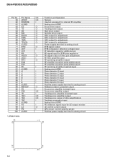
... power supply control output External relay output Test program mode input Not used Tuner power control output Reset input Not used (open) Not used (GND) GND Crystal oscillator connection pin Crystal oscillator connection pin Connect to VSS Capacitor for regulator connect pin Power supply Green illumination select output Not used A/D converter power supply output Amber illumination select output Power supply control output for IP BUS interface IC Slave power supply control output Not used System mute output RDS decoder power select output LOCL output LOCH output PLL IC chip enable output Clock...
... power supply control output External relay output Test program mode input Not used Tuner power control output Reset input Not used (open) Not used (GND) GND Crystal oscillator connection pin Crystal oscillator connection pin Connect to VSS Capacitor for regulator connect pin Power supply Green illumination select output Not used A/D converter power supply output Amber illumination select output Power supply control output for IP BUS interface IC Slave power supply control output Not used System mute output RDS decoder power select output LOCL output LOCH output PLL IC chip enable output Clock...

Service Manual
Page 50
... they are very 100 liable to be damaged by * are MOS type. DEH-P2000,P20,P2050 30 Pin No. 64 65 66 67 68 69 70 71 72 73 74 75 ...Function and Operation CD disc clamp sense input CD LSI clock output CD LSI data input CD LSI data output CD LSI command/data control output CD LSI reset output CD LSI strobe output Sub woofer electronic volume control output Sub woofer mute output Test terminal Tuner signal level input Model select input Not used CD disc EJECT position detect CD disc detect input CD VD over voltage / short-circuit sense input CD temperature sense input (CD) A/D converter power...
... they are very 100 liable to be damaged by * are MOS type. DEH-P2000,P20,P2050 30 Pin No. 64 65 66 67 68 69 70 71 72 73 74 75 ...Function and Operation CD disc clamp sense input CD LSI clock output CD LSI data input CD LSI data output CD LSI command/data control output CD LSI reset output CD LSI strobe output Sub woofer electronic volume control output Sub woofer mute output Test terminal Tuner signal level input Model select input Not used CD disc EJECT position detect CD disc detect input CD VD over voltage / short-circuit sense input CD temperature sense input (CD) A/D converter power...

Service Manual
Page 51
... 21 1 Function and Operation GND Crystal oscillator connection pin Crystal oscillator connection pin Not used Connect to GND Not used Key data output Display data input Remote control pulse input Not used Key data input Key strobe output VDD LCD segment output LCD common output LCD voltage input Power supply terminal BR9010FV 80 NC 1 8 WC 40 PAL005A 41 60 VCC 2 CS : Chip select input 7 SK : Serial data clock input DI : Serial data input DO : Serial data output CS...
... 21 1 Function and Operation GND Crystal oscillator connection pin Crystal oscillator connection pin Not used Connect to GND Not used Key data output Display data input Remote control pulse input Not used Key data input Key strobe output VDD LCD segment output LCD common output LCD voltage input Power supply terminal BR9010FV 80 NC 1 8 WC 40 PAL005A 41 60 VCC 2 CS : Chip select input 7 SK : Serial data clock input DI : Serial data input DO : Serial data output CS...
Service Manual
Page 54
...not use select for internal RF amplifier Analog circuit GND O Focus drive output O Tracking drive output O Sled drive output O Spindle drive output O DAC output for adjustment O DAC output for adjustment O DAC output for adjustment O DAC output for adjustment Power supply terminal to analog circuit O EFM signal output I EFM comparator reference voltage input 3T detection capacitor additional pin I RF signal input for EFM data regulation O RF signal output of after gain adjustment I RF-AGC amplifier input O RF summing amplifier output RF amplifier equalizer parts...
...not use select for internal RF amplifier Analog circuit GND O Focus drive output O Tracking drive output O Sled drive output O Spindle drive output O DAC output for adjustment O DAC output for adjustment O DAC output for adjustment O DAC output for adjustment Power supply terminal to analog circuit O EFM signal output I EFM comparator reference voltage input 3T detection capacitor additional pin I RF signal input for EFM data regulation O RF signal output of after gain adjustment I RF-AGC amplifier input O RF summing amplifier output RF amplifier equalizer parts...
Service Manual
Page 58
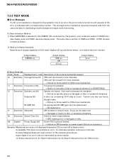
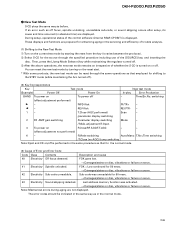
... below : 1x: Setup relevant errors, 3x: Search relevant errors, 3x: Search relevant errors, Ax: Other errors. 58 An intended operation continues in these errors). DEH-P2000,P20,P2050 7.2.2 TEST MODE - DTNO remains in blank as before. 2) Head unit display examples Depending on display capability of the error is written to the example given above. Sub-code is ground faulted. → Failure on SW transistor or power supply (failure...
... below : 1x: Setup relevant errors, 3x: Search relevant errors, 3x: Search relevant errors, Ax: Other errors. 58 An intended operation continues in these errors). DEH-P2000,P20,P2050 7.2.2 TEST MODE - DTNO remains in blank as before. 2) Head unit display examples Depending on display capability of the error is written to the example given above. Sub-code is ground faulted. → Failure on SW transistor or power supply (failure...
Service Manual
Page 59
... off is displayed. During setup, operational status of the [SOURCE] key, and inserting the disc. Time/Err.No. REV-Kick REV/TR- - 1- T.Close (AGC performed) Scan - /parameter display switching 2 RF AMP gain switching Parameter display switching Mode - /T.BAL adjustment/T.Open 3 To power on servo. 43 Electricity Sound skipping detected. Sub-code was activated. → Damages/stains on disc, vibrations or failure on servo. 42 Electricity Sub-code unreadable. If an error such as...
... off is displayed. During setup, operational status of the [SOURCE] key, and inserting the disc. Time/Err.No. REV-Kick REV/TR- - 1- T.Close (AGC performed) Scan - /parameter display switching 2 RF AMP gain switching Parameter display switching Mode - /T.BAL adjustment/T.Open 3 To power on servo. 43 Electricity Sound skipping detected. Sub-code was activated. → Damages/stains on disc, vibrations or failure on servo. 42 Electricity Sub-code unreadable. If an error such as...

Service Manual
Page 66
... Number Indicator Disc Search Switching the Display Each press of time. Switching the Multi-CD Player Using a multiple connection adapter lets you switch displays when disc titles have not been input, "NO TITLE" is displayed. M-CD 1 = M-CD 2 = M-CD 3 (Displayed about for a different length of the DISPLAY button changes the display in the following order: Playback mode (Elapsed play time) = Disc Title Note: • If you connect up to three Multi-CD players. DEH-P2000,P20,P2050 Basic Operation Basic Operation...
... Number Indicator Disc Search Switching the Display Each press of time. Switching the Multi-CD Player Using a multiple connection adapter lets you switch displays when disc titles have not been input, "NO TITLE" is displayed. M-CD 1 = M-CD 2 = M-CD 3 (Displayed about for a different length of the DISPLAY button changes the display in the following order: Playback mode (Elapsed play time) = Disc Title Note: • If you connect up to three Multi-CD players. DEH-P2000,P20,P2050 Basic Operation Basic Operation...
Service Manual
Page 67
... is selected for playback. Refer to Multi-CD Player's Owner's Manual for operation details. * Title display switching * Title scroll • You cannot switch to the Disc Title Input mode in moved from using the 1 to 5 buttons. DEH-P2000,P20,P2050 Disc Number Search (for 6-Disc, 12-Disc types) • You can use the 5 and ∞ buttons to . The 50 discs are no discs in the multi-CD player magazine, "NO DISC" is connected and you start playing a disc...
... is selected for playback. Refer to Multi-CD Player's Owner's Manual for operation details. * Title display switching * Title scroll • You cannot switch to the Disc Title Input mode in moved from using the 1 to 5 buttons. DEH-P2000,P20,P2050 Disc Number Search (for 6-Disc, 12-Disc types) • You can use the 5 and ∞ buttons to . The 50 discs are no discs in the multi-CD player magazine, "NO DISC" is connected and you start playing a disc...
Service Manual
Page 69
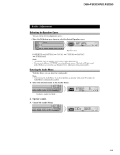
... can switch between Equalizer curves. • Move the EQ button up or down to select the desired Equalizer curve. Operate a mode. 3. Equalizer curve POWERFUL += NATURAL += VOCAL += CUSTOM += EQ FLAT += SUPER BASS Note: • "CUSTOM" stores an equalizer curve you have made adjustments to. • You can create different "CUSTOM" curves for different sources. (The built-in the Audio Menu. Cancel the Audio Menu. 69 Each press changes the Mode ... 2. DEH-P2000...
... can switch between Equalizer curves. • Move the EQ button up or down to select the desired Equalizer curve. Operate a mode. 3. Equalizer curve POWERFUL += NATURAL += VOCAL += CUSTOM += EQ FLAT += SUPER BASS Note: • "CUSTOM" stores an equalizer curve you have made adjustments to. • You can create different "CUSTOM" curves for different sources. (The built-in the Audio Menu. Cancel the Audio Menu. 69 Each press changes the Mode ... 2. DEH-P2000...
Service Manual
Page 70
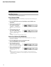
... you want to right. "BAL L 9" - EQ-LOW += EQ-MID += EQ-HIGH 3. The display shows "+6" - "BAL R 9" is displayed as desired. Adjusted equalizer curve settings are in all occupied seats. 1. Press the AUDIO button and select the Equalizer mode (EQ-LOW/MID/HIGH) in memory as it moves from left /right speaker balance with the 5/∞ buttons. DEH-P2000,P20,P2050 Audio Menu Functions The Audio Menu features the following functions. Adjust front/rear speaker balance with the...
... you want to right. "BAL L 9" - EQ-LOW += EQ-MID += EQ-HIGH 3. The display shows "+6" - "BAL R 9" is displayed as desired. Adjusted equalizer curve settings are in all occupied seats. 1. Press the AUDIO button and select the Equalizer mode (EQ-LOW/MID/HIGH) in memory as it moves from left /right speaker balance with the 5/∞ buttons. DEH-P2000,P20,P2050 Audio Menu Functions The Audio Menu features the following functions. Adjust front/rear speaker balance with the...
Service Manual
Page 72
... 2/3 buttons. 100 += 160 += 250 (Hz) Note: • After switching the F.I.E. to the same volume adjustment setting automatically. 1. DEH-P2000,P20,P2050 Front Image Enhancer Function (FIE) The F.I.E. (Front Image Enhancer) function is deactivated, the rear speakers output sound of all be adjusted. function is a simple method of enhancing front imaging by cutting mid- mode (FIE) in volume when switching between sources. Switch the F.I .E. function ON, select the Fader/Balance mode in the Audio Menu, and adjust front...
... 2/3 buttons. 100 += 160 += 250 (Hz) Note: • After switching the F.I.E. to the same volume adjustment setting automatically. 1. DEH-P2000,P20,P2050 Front Image Enhancer Function (FIE) The F.I.E. (Front Image Enhancer) function is deactivated, the rear speakers output sound of all be adjusted. function is a simple method of enhancing front imaging by cutting mid- mode (FIE) in volume when switching between sources. Switch the F.I .E. function ON, select the Fader/Balance mode in the Audio Menu, and adjust front...
Service Manual
Page 73
... the same function. + Front speaker ≠ Left + Rear speaker ≠ + Rear speaker ≠ Connecting cords with power regardless of ignition switch position. DEH-P2000,P20,P2050 73 Antenna jack This Product Multi-CD player (sold separately) IP-BUS cable Rear output IP-BUS input (Blue) Fuse Blue/white To system control terminal of the power amp or Auto-antenna relay control terminal. (Max. 300 mA 12 V DC.) Yellow To terminal always supplied with RCA pin plugs (sold separately) System remote control White White...
... the same function. + Front speaker ≠ Left + Rear speaker ≠ + Rear speaker ≠ Connecting cords with power regardless of ignition switch position. DEH-P2000,P20,P2050 73 Antenna jack This Product Multi-CD player (sold separately) IP-BUS cable Rear output IP-BUS input (Blue) Fuse Blue/white To system control terminal of the power amp or Auto-antenna relay control terminal. (Max. 300 mA 12 V DC.) Yellow To terminal always supplied with RCA pin plugs (sold separately) System remote control White White...


