Service Manual
Page 1
... 4. PIONEER ELECTRONIC [EUROPE] N.V. CRT2192 AV SYSTEM MONITOR AVX-505 UC - PCB CONNECTION DIAGRAM 30 5. Wait awhile after the power switch of Backlight • High voltage is generated in Japan CONTENTS 1. GENERAL INFORMATION 50 7.1 IC 50 7.2 DIAGNOSIS 51 7.2.1 DISASSEMBLY 51 7.2.2 TROUBLESHOOTING FOR LCD 5.5 MONITOR 58 7.3 EXPLANATION 68 7.3.1 MECHANISM DESCRIPTIONS 68 7.3.2 BLOCK DIAGRAM 70 8. ELECTRICAL PARTS...
... 4. PIONEER ELECTRONIC [EUROPE] N.V. CRT2192 AV SYSTEM MONITOR AVX-505 UC - PCB CONNECTION DIAGRAM 30 5. Wait awhile after the power switch of Backlight • High voltage is generated in Japan CONTENTS 1. GENERAL INFORMATION 50 7.1 IC 50 7.2 DIAGNOSIS 51 7.2.1 DISASSEMBLY 51 7.2.2 TROUBLESHOOTING FOR LCD 5.5 MONITOR 58 7.3 EXPLANATION 68 7.3.1 MECHANISM DESCRIPTIONS 68 7.3.2 BLOCK DIAGRAM 70 8. ELECTRICAL PARTS...
Service Manual
Page 2
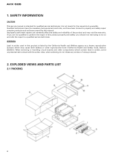
... and may cause birth defects or other components which may void the warranty. EXPLODED VIEWS AND PARTS LIST 2.1 PACKING 2 When servicing or handling circuit boards and other reproductive harm (California Health and Safety Code, Section 25249.5). AVX-505 1. Improperly performed repairs can adversely affect the safety and reliability of this manual. If you...
... and may cause birth defects or other components which may void the warranty. EXPLODED VIEWS AND PARTS LIST 2.1 PACKING 2 When servicing or handling circuit boards and other reproductive harm (California Health and Safety Code, Section 25249.5). AVX-505 1. Improperly performed repairs can adversely affect the safety and reliability of this manual. If you...
Service Manual
Page 3
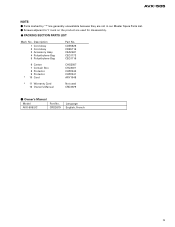
.... - Description 1 Cord Assy 2 Cord Assy 3 Accessory Assy 4 Polyethylene Bag 5 Polyethylene Bag Part No. Owner's Manual Model AVX-505/UC Part No. Parts marked by "*"are generally unavailable because they are used CRD2679 - PACKING SECTION PARTS LIST Mark No. CRD2679 Language English, French 3 AVX-505 NOTE: - CDE5626 CDE5716 CEA2467 CEG1173 CEG1116 6 Carton 7 Contain Box 8 Protector 9 Protector * 10 Card CHG3507...
.... - Description 1 Cord Assy 2 Cord Assy 3 Accessory Assy 4 Polyethylene Bag 5 Polyethylene Bag Part No. Owner's Manual Model AVX-505/UC Part No. Parts marked by "*"are generally unavailable because they are used CRD2679 - PACKING SECTION PARTS LIST Mark No. CRD2679 Language English, French 3 AVX-505 NOTE: - CDE5626 CDE5716 CEA2467 CEG1173 CEG1116 6 Carton 7 Contain Box 8 Protector 9 Protector * 10 Card CHG3507...
Service Manual
Page 7
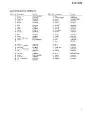
AVX-505 - Description 1 Screw 2 Spring 3 Grille Unit 4 Screw 5 Handle Part No. CNS4011 CWM5896 BPZ20P080FMC CAC5180 CBA1215 CBH2099 CBH2100 CBH2107 CKS2780 CNC7643 CNC7644 CNC7645 CNM5032 CNP5168 CNV5311 CNV5312 CNV5313 CXB2378 CNS4898 CBH2101 BPZ20P100FZK CAC5547 CAC5548 CAC5549 7 ... 38 Sheet 39 PCB 40 Arm 41 Arm 42 Arm 43 Panel Unit 44 Cover 45 Spring 46 Screw 47 Button 48 Button 49 Button Part No. EXTERIOR SECTION (1) PARTS LIST Mark No.
AVX-505 - Description 1 Screw 2 Spring 3 Grille Unit 4 Screw 5 Handle Part No. CNS4011 CWM5896 BPZ20P080FMC CAC5180 CBA1215 CBH2099 CBH2100 CBH2107 CKS2780 CNC7643 CNC7644 CNC7645 CNM5032 CNP5168 CNV5311 CNV5312 CNV5313 CXB2378 CNS4898 CBH2101 BPZ20P100FZK CAC5547 CAC5548 CAC5549 7 ... 38 Sheet 39 PCB 40 Arm 41 Arm 42 Arm 43 Panel Unit 44 Cover 45 Spring 46 Screw 47 Button 48 Button 49 Button Part No. EXTERIOR SECTION (1) PARTS LIST Mark No.
Service Manual
Page 9
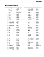
...48 Connector(CN932) 49 Connector(CN939) 50 Connector(CN933) BMZ30P060FMC CKS2235 CKS2258 CKS2260 CKS3124 Mark No. AVX-505 - Description 1 Cord Assy 2 Resistor 3 Cap 4 Cord Assy 5 Drive Mechanism Unit Part No. Description 51 Connector(CN934) 52 Connector(CN935) 53 Connector(CN937) 54 Connector(CN936) 55 ... Connector(CN100) 92 Holder 93 Holder 94 Clamper 95 Screw 96 Spring 97 Transistor(Q931) 98 Connector(CN500) 99 Screw Part No. CKS3124 CKS3124 CKS3125 CKS3126 CNC6695 CNM5849 CNC6506 CNM4892 CNM5001 CXA8990 CXA8992 CXA9007 CXA9624 CXA9627 CXA9679 CXB2591 CXX1251 CNM5034 CNM5038 CNM5049...
...48 Connector(CN932) 49 Connector(CN939) 50 Connector(CN933) BMZ30P060FMC CKS2235 CKS2258 CKS2260 CKS3124 Mark No. AVX-505 - Description 1 Cord Assy 2 Resistor 3 Cap 4 Cord Assy 5 Drive Mechanism Unit Part No. Description 51 Connector(CN934) 52 Connector(CN935) 53 Connector(CN937) 54 Connector(CN936) 55 ... Connector(CN100) 92 Holder 93 Holder 94 Clamper 95 Screw 96 Spring 97 Transistor(Q931) 98 Connector(CN500) 99 Screw Part No. CKS3124 CKS3124 CKS3125 CKS3126 CNC6695 CNM5849 CNC6506 CNM4892 CNM5001 CXA8990 CXA8992 CXA9007 CXA9624 CXA9627 CXA9679 CXB2591 CXX1251 CNM5034 CNM5038 CNM5049...
Service Manual
Page 10
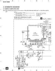
A B C RESET D A 10 B 1 2 3 4 SCHEMATIC DIAGRAM A 3.1 MICRO COMPUTER UNIT Note: When ordering service parts, be sure to refer to "EXPLODED VIEWS AND PARTS LIST" or "ELECTRICAL PARTS LIST". 1 2 3 4 AVX-505 3.
A B C RESET D A 10 B 1 2 3 4 SCHEMATIC DIAGRAM A 3.1 MICRO COMPUTER UNIT Note: When ordering service parts, be sure to refer to "EXPLODED VIEWS AND PARTS LIST" or "ELECTRICAL PARTS LIST". 1 2 3 4 AVX-505 3.
Service Manual
Page 30
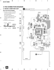
Viewpoint of PCB diagrams A MICRO COMPUTER UNIT Connector Capacitor SIDE A B P.C.Board Chip Part SIDE B C D A 30 1 2 B CN900 R 3 4 1 2 3 4 AVX-505 4. The parts mounted on this PCB include all necessary parts for respective destinations, be sure to check with the schematic diagram. 2. For further information for several destination. PCB CONNECTION DIAGRAM 4.1 MICRO COMPUTER UNIT A NOTE FOR PCB DIAGRAMS 1.
Viewpoint of PCB diagrams A MICRO COMPUTER UNIT Connector Capacitor SIDE A B P.C.Board Chip Part SIDE B C D A 30 1 2 B CN900 R 3 4 1 2 3 4 AVX-505 4. The parts mounted on this PCB include all necessary parts for respective destinations, be sure to check with the schematic diagram. 2. For further information for several destination. PCB CONNECTION DIAGRAM 4.1 MICRO COMPUTER UNIT A NOTE FOR PCB DIAGRAMS 1.
Service Manual
Page 42
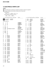
... 2SC4177 2SC4177 2SC4177 2SC4177 2SA1611 2SA1611 2SA1611 2SC4177 2SC4177 2SC4177 2SC4177 2SD999 2SB798 2SK160 2SJ316 2SB1123T 2SA1832 2SJ316 2SK1470 2SA1832 2SB1123T =====Circuit Symbol and No.===Part Name Q 908 Q 909 Q 910 D 1 D 2 Transistor Transistor Transistor Diode Diode D 3 Diode D 4 Diode D 5 Diode D 6 Diode D 7 Diode D 8 Diode D 701 Diode D 702 ...CZC5116 CZT3078 CZT3078 CZT3077 CZT3077 CZS3028 CZS3027 CZC5099 CZC5099 CZC5095 CZC5095 CZC5100 CZC5096 CZC5100 42 The part numbers shown below indicate chip components. ELECTRICAL PARTS LIST NOTE: - AVX-505 5.
... 2SC4177 2SC4177 2SC4177 2SC4177 2SA1611 2SA1611 2SA1611 2SC4177 2SC4177 2SC4177 2SC4177 2SD999 2SB798 2SK160 2SJ316 2SB1123T 2SA1832 2SJ316 2SK1470 2SA1832 2SB1123T =====Circuit Symbol and No.===Part Name Q 908 Q 909 Q 910 D 1 D 2 Transistor Transistor Transistor Diode Diode D 3 Diode D 4 Diode D 5 Diode D 6 Diode D 7 Diode D 8 Diode D 701 Diode D 702 ...CZC5116 CZT3078 CZT3078 CZT3077 CZT3077 CZS3028 CZS3027 CZC5099 CZC5099 CZC5095 CZC5095 CZC5100 CZC5096 CZC5100 42 The part numbers shown below indicate chip components. ELECTRICAL PARTS LIST NOTE: - AVX-505 5.
Service Manual
Page 43
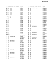
AVX-505 =====Circuit Symbol and No.===Part Name VR 305 VR 306 VR 307 VR 308 VR... 309 Volume Volume Volume Volume Volume VR 801 VR 802 VR 901 VR 902 VR 903 Volume Volume Volume Volume Volume VR 904 F 901 F 1 F 601 F 101 Volume Fuse Fuse F 102 EF 102 EF 503 EF 504 EF 505.../16-222F) R 27 (RMC1/16-203F) R 28 R 29 R 30 R 31 R 32 (RMC1/16-512F) R 33 Part No CZC5100 CZC5100 CZC5095 CZC5100 CZC5100 CZC5095 CZC5095 CZC5099 CZC5099 CZC5095 CZC5100 CZE3024 CZE3024 RS1/10S0R0J CZC5093 CZC5094 CCG1067 CCG1067 CCG1067 CCG1067 CCG1067 CCG1067 CCG1067...
AVX-505 =====Circuit Symbol and No.===Part Name VR 305 VR 306 VR 307 VR 308 VR... 309 Volume Volume Volume Volume Volume VR 801 VR 802 VR 901 VR 902 VR 903 Volume Volume Volume Volume Volume VR 904 F 901 F 1 F 601 F 101 Volume Fuse Fuse F 102 EF 102 EF 503 EF 504 EF 505.../16-222F) R 27 (RMC1/16-203F) R 28 R 29 R 30 R 31 R 32 (RMC1/16-512F) R 33 Part No CZC5100 CZC5100 CZC5095 CZC5100 CZC5100 CZC5095 CZC5095 CZC5099 CZC5099 CZC5095 CZC5100 CZE3024 CZE3024 RS1/10S0R0J CZC5093 CZC5094 CCG1067 CCG1067 CCG1067 CCG1067 CCG1067 CCG1067 CCG1067...
Service Manual
Page 45
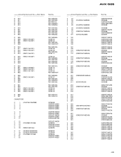
AVX-505 =====Circuit Symbol and No.===Part Name R 810 R 811 R 812 R 813 R 814 R 815 R 901 R 902 R 903 R 904 R 905 R 906 (RMC1/16-203F) R 907 (RMC1/16-203F) R.../10S471J CZC5088 CKSRYF104Z25 CKSRYF104Z25 CKSRYF104Z25 CKSRYF104Z25 CKSRYB103K50 CKSRYF104Z25 CKSQYF104Z50 CKSRYF104Z25 CCSRCH331J50 CKSQYF104Z50 CZC5092 CKSRYB471K50 CKSRYB471K50 CZC5090 CZC5084 CZC5084 CZC5092 CKSRYF104Z25 CKSRYF104Z25 =====Circuit Symbol and No.===Part Name C 24 C 25 (CX43Y5U106Z25B) C 26 C 27 C 28 (CX43Y5U106Z25B) C 29 (CX43Y5U106Z25B) C 30 C 31 (CM32Y5V105Z50A) C 32 C 101 (SVHD21A336M) C 102 C 103 C 104 C 105...
AVX-505 =====Circuit Symbol and No.===Part Name R 810 R 811 R 812 R 813 R 814 R 815 R 901 R 902 R 903 R 904 R 905 R 906 (RMC1/16-203F) R 907 (RMC1/16-203F) R.../10S471J CZC5088 CKSRYF104Z25 CKSRYF104Z25 CKSRYF104Z25 CKSRYF104Z25 CKSRYB103K50 CKSRYF104Z25 CKSQYF104Z50 CKSRYF104Z25 CCSRCH331J50 CKSQYF104Z50 CZC5092 CKSRYB471K50 CKSRYB471K50 CZC5090 CZC5084 CZC5084 CZC5092 CKSRYF104Z25 CKSRYF104Z25 =====Circuit Symbol and No.===Part Name C 24 C 25 (CX43Y5U106Z25B) C 26 C 27 C 28 (CX43Y5U106Z25B) C 29 (CX43Y5U106Z25B) C 30 C 31 (CM32Y5V105Z50A) C 32 C 101 (SVHD21A336M) C 102 C 103 C 104 C 105...
Service Manual
Page 54
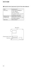
Panel No. 54 AVX-505 - Replacement should be made according to page 57. Same as above Rear frame Product name, Lot No. Precautions after replacement of parts of the LCD 5.5 Monitor Parts Rear frame Substrate Unit Backlight Assy Side frame Checking point Product name (NL3224xxx) Lot No. (B65xxx) Panel No. (K026xxx) For quality control of the LCD 5.5 Monitor, write down: Adjust flicker in advance.
Panel No. 54 AVX-505 - Replacement should be made according to page 57. Same as above Rear frame Product name, Lot No. Precautions after replacement of parts of the LCD 5.5 Monitor Parts Rear frame Substrate Unit Backlight Assy Side frame Checking point Product name (NL3224xxx) Lot No. (B65xxx) Panel No. (K026xxx) For quality control of the LCD 5.5 Monitor, write down: Adjust flicker in advance.
Service Manual
Page 55
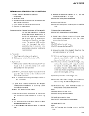
...the lamp is broken inside the Backlight Assy, remove the assembly with a cleanbench (equivalent to Class C) or in the lamp holder compartment. AVX-505 - To avoid this, replacement should be a possibility of pieces of broken glass. Replacement (1) Set the power switch of the Backlight Assy ...(12) Hook the cable of the Backlight Assy on the two tabs ("a" in Fig. 6. Notes: 1) Do NOT damage the electrical parts on parts "a" (three places) to ON. 3. Facilities and tools required for replacement Recommendation: Uneven luminance will be damaged by static electricity. Replacement ...
...the lamp is broken inside the Backlight Assy, remove the assembly with a cleanbench (equivalent to Class C) or in the lamp holder compartment. AVX-505 - To avoid this, replacement should be a possibility of pieces of broken glass. Replacement (1) Set the power switch of the Backlight Assy ...(12) Hook the cable of the Backlight Assy on the two tabs ("a" in Fig. 6. Notes: 1) Do NOT damage the electrical parts on parts "a" (three places) to ON. 3. Facilities and tools required for replacement Recommendation: Uneven luminance will be damaged by static electricity. Replacement ...
Service Manual
Page 56
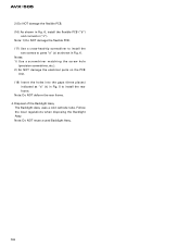
... the PCB Unit. (18) Insert the holes into the gaps (three places) indicated as "a" (∆) in Fig. 5 to parts "a" (∆) as shown in Fig. 6, install the flexible PCB ("b") and connector ("c"). Note: 1) Do NOT damage the flexible PCB. (17) Use a cross-head-tip screwdriver to ... Backlight Assy The Backlight Assy uses a cold cathode tube. Follow the local regulations when disposing the Backlight Assy. Note: Do NOT deform the rear frame. 4. AVX-505 2) Do NOT damage the flexible PCB. (16) As shown in Fig. 6. Note: Do NOT reuse a used Backlight Assy. 56
... the PCB Unit. (18) Insert the holes into the gaps (three places) indicated as "a" (∆) in Fig. 5 to parts "a" (∆) as shown in Fig. 6, install the flexible PCB ("b") and connector ("c"). Note: 1) Do NOT damage the flexible PCB. (17) Use a cross-head-tip screwdriver to ... Backlight Assy The Backlight Assy uses a cold cathode tube. Follow the local regulations when disposing the Backlight Assy. Note: Do NOT deform the rear frame. 4. AVX-505 2) Do NOT damage the flexible PCB. (16) As shown in Fig. 6. Note: Do NOT reuse a used Backlight Assy. 56


