Service Manual
Page 1
... power to OFF, then start operation. • In some cases, the cold cathode tube of backlight may be damaged. ADJUSTMENT 49 7. PCB CONNECTION DIAGRAM 30 5. Wait awhile after turning the power to the system. APR. 1998 Printed in the inverter when the power is set to OFF. SAFETY INFORMATION 2 2. CRT2192 AV SYSTEM MONITOR AVX-505 UC - Precautions on Safety for injury during operation. PIONEER...
... power to OFF, then start operation. • In some cases, the cold cathode tube of backlight may be damaged. ADJUSTMENT 49 7. PCB CONNECTION DIAGRAM 30 5. Wait awhile after turning the power to the system. APR. 1998 Printed in the inverter when the power is set to OFF. SAFETY INFORMATION 2 2. CRT2192 AV SYSTEM MONITOR AVX-505 UC - Precautions on Safety for injury during operation. PIONEER...
Service Manual
Page 2
... INFORMATION CAUTION This service manual is not meant for qualified service technicians; Improperly performed repairs can adversely affect the safety and reliability of this manual. When servicing or handling circuit boards and other reproductive harm (California Health and Safety Code, Section 25249.5). AVX-505 1. it is intended for the casual do not inhale any smoke or fumes produced. 2. EXPLODED VIEWS AND PARTS...
... INFORMATION CAUTION This service manual is not meant for qualified service technicians; Improperly performed repairs can adversely affect the safety and reliability of this manual. When servicing or handling circuit boards and other reproductive harm (California Health and Safety Code, Section 25249.5). AVX-505 1. it is intended for the casual do not inhale any smoke or fumes produced. 2. EXPLODED VIEWS AND PARTS...
Service Manual
Page 3
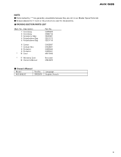
... Card 12 Owner's Manual Not used for disassembly. - PACKING SECTION PARTS LIST Mark No. Owner's Manual Model AVX-505/UC Part No. Screws adjacent to ∇ mark on the product are not in our Master Spare Parts List. - CRD2679 Language English, French 3 Parts marked by "*"are generally unavailable because they are used CRD2679 - Description 1 Cord Assy 2 Cord Assy 3 Accessory Assy 4 Polyethylene Bag 5 Polyethylene Bag Part No. AVX-505 NOTE: -
... Card 12 Owner's Manual Not used for disassembly. - PACKING SECTION PARTS LIST Mark No. Owner's Manual Model AVX-505/UC Part No. Screws adjacent to ∇ mark on the product are not in our Master Spare Parts List. - CRD2679 Language English, French 3 Parts marked by "*"are generally unavailable because they are used CRD2679 - Description 1 Cord Assy 2 Cord Assy 3 Accessory Assy 4 Polyethylene Bag 5 Polyethylene Bag Part No. AVX-505 NOTE: -
Service Manual
Page 7
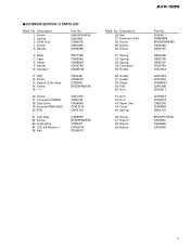
AVX-505 - EXTERIOR SECTION (1) PARTS LIST Mark No. CNS4011 CWM5896 BPZ20P080FMC CAC5180 CBA1215 CBH2099 CBH2100 CBH2107 CKS2780 CNC7643 CNC7644 CNC7645 CNM5032 CNP5168 CNV5311 CNV5312 CNV5313 CXB2378 CNS4898 CBH2101 BPZ20P100FZK CAC5547 CAC5548 CAC5549 7 Description 1 Screw 2 Spring 3 Grille Unit 4 Screw 5 Handle Part...Connector(CN900) 18 Sub Grille 19 Volume(VR951,952) 20 PCB CBA1378 CKS2733 CNS4900 CCW1019 CNP5119 21 LCD Assy 22 Screw 23 Grille Assy 24 LCD 5.5 Monitor 25 Rail CXB2539 BPZ20P080FZK CXB2377 CWX2010 CNS4010 Mark No. Description 26 Rail 27 Keyboard Unit 28 Screw 29 Button...
AVX-505 - EXTERIOR SECTION (1) PARTS LIST Mark No. CNS4011 CWM5896 BPZ20P080FMC CAC5180 CBA1215 CBH2099 CBH2100 CBH2107 CKS2780 CNC7643 CNC7644 CNC7645 CNM5032 CNP5168 CNV5311 CNV5312 CNV5313 CXB2378 CNS4898 CBH2101 BPZ20P100FZK CAC5547 CAC5548 CAC5549 7 Description 1 Screw 2 Spring 3 Grille Unit 4 Screw 5 Handle Part...Connector(CN900) 18 Sub Grille 19 Volume(VR951,952) 20 PCB CBA1378 CKS2733 CNS4900 CCW1019 CNP5119 21 LCD Assy 22 Screw 23 Grille Assy 24 LCD 5.5 Monitor 25 Rail CXB2539 BPZ20P080FZK CXB2377 CWX2010 CNS4010 Mark No. Description 26 Rail 27 Keyboard Unit 28 Screw 29 Button...
Service Manual
Page 9
... 71 Sheet 72 Screw 73 Switch(S932) 74 Switch(S933) 75 Chassis Assy 76 Screw 77 Washer 78 Chassis 79 Insulator 80 Rack 81 Roller 82 Rail Unit(L) 83 Rail Unit(R) 84 Holder 85 Speaker 86 Micro Computer Unit 87 Plug(CN200) 88 Connector(CN501) 89 90 Connector(CN502) 91 Connector(CN100) 92 Holder 93 Holder... CNV4587 CXA8988 CXA8989 CNC7718 CPV1041 CWM5895 CKS-461 CKS2258 CKS3645 CKS3822 CNC7646 CNC7647 CNV1335 BMZ20P040FMC CBL1277 2SD2396 CKS3124 CBA1457 9 EXTERIOR SECTION (2) PARTS LIST Mark No. Description 1 Cord Assy 2 Resistor 3 Cap 4 Cord Assy 5 Drive Mechanism Unit Part No. AVX-505 -
... 71 Sheet 72 Screw 73 Switch(S932) 74 Switch(S933) 75 Chassis Assy 76 Screw 77 Washer 78 Chassis 79 Insulator 80 Rack 81 Roller 82 Rail Unit(L) 83 Rail Unit(R) 84 Holder 85 Speaker 86 Micro Computer Unit 87 Plug(CN200) 88 Connector(CN501) 89 90 Connector(CN502) 91 Connector(CN100) 92 Holder 93 Holder... CNV4587 CXA8988 CXA8989 CNC7718 CPV1041 CWM5895 CKS-461 CKS2258 CKS3645 CKS3822 CNC7646 CNC7647 CNV1335 BMZ20P040FMC CBL1277 2SD2396 CKS3124 CBA1457 9 EXTERIOR SECTION (2) PARTS LIST Mark No. Description 1 Cord Assy 2 Resistor 3 Cap 4 Cord Assy 5 Drive Mechanism Unit Part No. AVX-505 -
Service Manual
Page 10
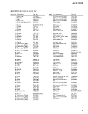
A B C RESET D A 10 B 1 2 3 4 SCHEMATIC DIAGRAM A 3.1 MICRO COMPUTER UNIT Note: When ordering service parts, be sure to refer to "EXPLODED VIEWS AND PARTS LIST" or "ELECTRICAL PARTS LIST". 1 2 3 4 AVX-505 3.
A B C RESET D A 10 B 1 2 3 4 SCHEMATIC DIAGRAM A 3.1 MICRO COMPUTER UNIT Note: When ordering service parts, be sure to refer to "EXPLODED VIEWS AND PARTS LIST" or "ELECTRICAL PARTS LIST". 1 2 3 4 AVX-505 3.
Service Manual
Page 30
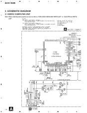
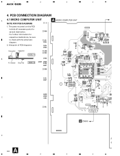
PCB CONNECTION DIAGRAM 4.1 MICRO COMPUTER UNIT A NOTE FOR PCB DIAGRAMS 1. For further information for several destination. 1 2 3 4 AVX-505 4. Viewpoint of PCB diagrams A MICRO COMPUTER UNIT Connector Capacitor SIDE A B P.C.Board Chip Part SIDE B C D A 30 1 2 B CN900 R 3 4 The parts mounted on this PCB include all necessary parts for respective destinations, be sure to check with the schematic diagram. 2.
PCB CONNECTION DIAGRAM 4.1 MICRO COMPUTER UNIT A NOTE FOR PCB DIAGRAMS 1. For further information for several destination. 1 2 3 4 AVX-505 4. Viewpoint of PCB diagrams A MICRO COMPUTER UNIT Connector Capacitor SIDE A B P.C.Board Chip Part SIDE B C D A 30 1 2 B CN900 R 3 4 The parts mounted on this PCB include all necessary parts for respective destinations, be sure to check with the schematic diagram. 2.
Service Manual
Page 43
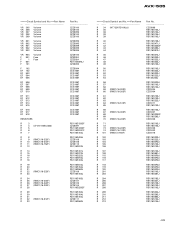
AVX-505 =====Circuit Symbol and No.===Part Name VR 305 VR 306 VR 307 VR 308 VR 309 Volume Volume Volume Volume Volume VR 801 VR 802 VR 901 VR 902 VR 903 Volume Volume Volume Volume Volume VR 904 F 901 F 1 F 601 F 101 Volume Fuse Fuse F 102 EF 102 EF 503 EF 504 EF 505 EF 506 EF 507 EF... (RMC1/16-303F) R 26 (RMC1/16-222F) R 27 (RMC1/16-203F) R 28 R 29 R 30 R 31 R 32 (RMC1/16-512F) R 33 Part No CZC5100 CZC5100 CZC5095 CZC5100 CZC5100 CZC5095 CZC5095 CZC5099 CZC5099 CZC5095 CZC5100 CZE3024 CZE3024 RS1/10S0R0J CZC5093 CZC5094 CCG1067 CCG1067 CCG1067 CCG1067 CCG1067 CCG1067 CCG1067...
AVX-505 =====Circuit Symbol and No.===Part Name VR 305 VR 306 VR 307 VR 308 VR 309 Volume Volume Volume Volume Volume VR 801 VR 802 VR 901 VR 902 VR 903 Volume Volume Volume Volume Volume VR 904 F 901 F 1 F 601 F 101 Volume Fuse Fuse F 102 EF 102 EF 503 EF 504 EF 505 EF 506 EF 507 EF... (RMC1/16-303F) R 26 (RMC1/16-222F) R 27 (RMC1/16-203F) R 28 R 29 R 30 R 31 R 32 (RMC1/16-512F) R 33 Part No CZC5100 CZC5100 CZC5095 CZC5100 CZC5100 CZC5095 CZC5095 CZC5099 CZC5099 CZC5095 CZC5100 CZE3024 CZE3024 RS1/10S0R0J CZC5093 CZC5094 CCG1067 CCG1067 CCG1067 CCG1067 CCG1067 CCG1067 CCG1067...
Service Manual
Page 49
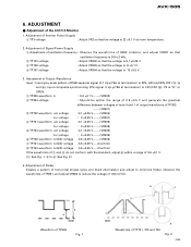
... not conform with the standard, adjust 6 within the range of 2.5 ±0.5 V and generate the greatest difference between voltages of tone 0 and 1 of output waveforms of Invertor Power Supply 1 TP3 voltage : Adjust VR2 so that the voltage is "H" or OPEN. 1 TP305 waveform b : 9.0 ±0.1 V VR302) 2 TP304 voltage : Should be within a range of the LCD 5.5 Monitor 1. Adjustment of 3.6 ±0.1 V. (1: See Fig...
... not conform with the standard, adjust 6 within the range of 2.5 ±0.5 V and generate the greatest difference between voltages of tone 0 and 1 of output waveforms of Invertor Power Supply 1 TP3 voltage : Adjust VR2 so that the voltage is "H" or OPEN. 1 TP305 waveform b : 9.0 ±0.1 V VR302) 2 TP304 voltage : Should be within a range of the LCD 5.5 Monitor 1. Adjustment of 3.6 ±0.1 V. (1: See Fig...

Service Manual
Page 50
...C Function and Operation Key data input Not used A/D converter GND Not used A/D converter reference voltage Not used Not used Not used Not used GND Not used Keyboard Unit power supply control output Display dimmer output Not used Not used LCD back light power supply control output Motor power supply control output Beep tone output Motor position control output Motor speed control output Motor position control output Monitor position sense control input 0 degree switch input Lift switch input Monitor degree sense input Not used Not used Not used Not used Not used Illumination power sense input...
...C Function and Operation Key data input Not used A/D converter GND Not used A/D converter reference voltage Not used Not used Not used Not used GND Not used Keyboard Unit power supply control output Display dimmer output Not used Not used LCD back light power supply control output Motor power supply control output Beep tone output Motor position control output Motor speed control output Motor position control output Monitor position sense control input 0 degree switch input Lift switch input Monitor degree sense input Not used Not used Not used Not used Not used Illumination power sense input...

Service Manual
Page 51
... of the Case to remove the Panel. 2. Removing the Panel Unit 1. Removing the Micro Computer Unit 1. ector. Remove the two rails. 3. Removing the Case (Not shown) 1. Remove screw D, then pull out the Monitor. Remove the three screws A to remove it. - Remove the four screws E. Rail F F E E PCB Connector F LCD Assy F Rail FE E F 51 Press the button indicated with arrows. 4. A B Micro Computer Unit A Panel B A B B - AVX-505 7.2 DIAGNOSIS 7.2.1 DISASSEMBLY - Upright the...
... of the Case to remove the Panel. 2. Removing the Panel Unit 1. Removing the Micro Computer Unit 1. ector. Remove the two rails. 3. Removing the Case (Not shown) 1. Remove screw D, then pull out the Monitor. Remove the three screws A to remove it. - Remove the four screws E. Rail F F E E PCB Connector F LCD Assy F Rail FE E F 51 Press the button indicated with arrows. 4. A B Micro Computer Unit A Panel B A B B - AVX-505 7.2 DIAGNOSIS 7.2.1 DISASSEMBLY - Upright the...

Service Manual
Page 53
... Drive Mechanism Unit is installed as shown in incorrect operation of the Drive Mechanism Unit 1. AVX-505 - PCB Volume Unit Sheet Insulator Frame Unit Fig. 4 - Remove the connector to remove the PCB and Volume Unit. Remove the connector to remove the Keyboard Unit. - Frame Unit Insulator Fig. 3 Keyboard Unit - Mark Rail Unit (L) Spring Guide Rail Unit (R) Drive Mechanism Unit 53 Check the mark on assembly of the Monitor. Precautions on assembly of the Case Unit Install the...
... Drive Mechanism Unit is installed as shown in incorrect operation of the Drive Mechanism Unit 1. AVX-505 - PCB Volume Unit Sheet Insulator Frame Unit Fig. 4 - Remove the connector to remove the PCB and Volume Unit. Remove the connector to remove the Keyboard Unit. - Frame Unit Insulator Fig. 3 Keyboard Unit - Mark Rail Unit (L) Spring Guide Rail Unit (R) Drive Mechanism Unit 53 Check the mark on assembly of the Monitor. Precautions on assembly of the Case Unit Install the...
Service Manual
Page 54
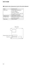
AVX-505 - Panel No. 54 Replacement should be made according to page 57. Same as above Rear frame Product name, Lot No. Precautions after replacement of parts of the LCD 5.5 Monitor Parts Rear frame Substrate Unit Backlight Assy Side frame Checking point Product name (NL3224xxx) Lot No. (B65xxx) Panel No. (K026xxx) For quality control of the LCD 5.5 Monitor, write down: Adjust flicker in advance.
AVX-505 - Panel No. 54 Replacement should be made according to page 57. Same as above Rear frame Product name, Lot No. Precautions after replacement of parts of the LCD 5.5 Monitor Parts Rear frame Substrate Unit Backlight Assy Side frame Checking point Product name (NL3224xxx) Lot No. (B65xxx) Panel No. (K026xxx) For quality control of the LCD 5.5 Monitor, write down: Adjust flicker in advance.
Service Manual
Page 55
AVX-505 - Facilities and tools required for operation (1) Fingerstalls (2) Grounding band (3) Workbench with conductive mat (workbench with electrostatic protection. To avoid this, replacement should be damaged by static electricity. Replacement (1) Set the power switch of ionizer (or other electrostatic protection facilities) is recommended. 2. Note: Do NOT deform the rear frame. (4) Use a cross-head-tip screwdriver to remove the two screws from the two...
AVX-505 - Facilities and tools required for operation (1) Fingerstalls (2) Grounding band (3) Workbench with conductive mat (workbench with electrostatic protection. To avoid this, replacement should be damaged by static electricity. Replacement (1) Set the power switch of ionizer (or other electrostatic protection facilities) is recommended. 2. Note: Do NOT deform the rear frame. (4) Use a cross-head-tip screwdriver to remove the two screws from the two...

Service Manual
Page 57
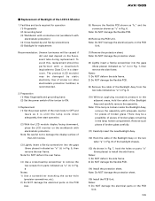
... the surface of the LCD module from breaking, be sure to connect the lamp cable into its original gap. (See step (13) of the replacement procedures.) • The cables of the flexible PCB and backlight may occur if you touch the connector located in the rear panel of glass. Take safety measures against static electricity (grounding band, ion shower, etc...
... the surface of the LCD module from breaking, be sure to connect the lamp cable into its original gap. (See step (13) of the replacement procedures.) • The cables of the flexible PCB and backlight may occur if you touch the connector located in the rear panel of glass. Take safety measures against static electricity (grounding band, ion shower, etc...

Service Manual
Page 61
...177;1.0 V? NO Check whether power is turned ON. YES NO B1 NO B2 NO Replace U903. Is the voltage 18 ±1.0 V? Connect CN1 and CN3 NO correctly. Check the voltage of TP105. Is the voltage 5 ±0.5 V? YES To the next page AVX-505 61 YES Replace F901. YES Check the ...voltage of CN1-8, 9 and PWRVI. Is the voltage 12.5 ±1.0 V? Check the system power NO and correct. YES Check connection between CN1 and CN3. Display shows white screen when the power is supplied to F901. Check the ...
...177;1.0 V? NO Check whether power is turned ON. YES NO B1 NO B2 NO Replace U903. Is the voltage 18 ±1.0 V? Connect CN1 and CN3 NO correctly. Check the voltage of TP105. Is the voltage 5 ±0.5 V? YES To the next page AVX-505 61 YES Replace F901. YES Check the ...voltage of CN1-8, 9 and PWRVI. Is the voltage 12.5 ±1.0 V? Check the system power NO and correct. YES Check connection between CN1 and CN3. Display shows white screen when the power is supplied to F901. Check the ...

Service Manual
Page 68
... enters Brake mode by using the forward/backward driving motor and the angle controlling motor. 2. To detect statuses and positions of operation 1. Encoder pulse Conditions for input to controlling microcomputer : H = 5 V, L = 0 V Error timer (time to OFF. 3. Operation stops mechanically when the motor withdraws. Withdraws slowly. 68 AVX-505 7.3 EXPLANATION 7.3.1 MECHANISM DESCRIPTIONS - Outline of operation, the system detects pulses by the Reset button. Then, the system ejects the monitor...
... enters Brake mode by using the forward/backward driving motor and the angle controlling motor. 2. To detect statuses and positions of operation 1. Encoder pulse Conditions for input to controlling microcomputer : H = 5 V, L = 0 V Error timer (time to OFF. 3. Operation stops mechanically when the motor withdraws. Withdraws slowly. 68 AVX-505 7.3 EXPLANATION 7.3.1 MECHANISM DESCRIPTIONS - Outline of operation, the system detects pulses by the Reset button. Then, the system ejects the monitor...

Service Manual
Page 69
... until the Position Sensing switch (Lift switch) is set to be output. Then, the system enters Brake mode. 2. The system stops the angle motor when the Angle Sensing switch (Angle 0 switch) is pressed. Precautions: angle upward/downward. 1. The system operates in contact mechanically. AVX-505 Comes in the same manner when the DOWN key is set to drive the display - Storage 1. Angle motor...
... until the Position Sensing switch (Lift switch) is set to be output. Then, the system enters Brake mode. 2. The system stops the angle motor when the Angle Sensing switch (Angle 0 switch) is pressed. Precautions: angle upward/downward. 1. The system operates in contact mechanically. AVX-505 Comes in the same manner when the DOWN key is set to drive the display - Storage 1. Angle motor...

Service Manual
Page 71
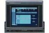
... with power regardless of ignition switch position. Fuse holder Fuse resistor Fuse resistor 71 Brightness control Volume control AVX-505 Monitor OPEN/CLOSE button Signal receptor ANGLE button DETACH button Note: • Use the remote control products for the AUDIO VISUAL MASTER UNIT by ignition switch (12 V DC) ON/OFF. Yellow To lighting switch terminal. OPERATIONS AND SPECIFICATIONS AV Monitor System The following diagram shows the monitor when it is deployed. Red To electric terminal controlled by pointing them at this product's signal receptor. Black (ground...
... with power regardless of ignition switch position. Fuse holder Fuse resistor Fuse resistor 71 Brightness control Volume control AVX-505 Monitor OPEN/CLOSE button Signal receptor ANGLE button DETACH button Note: • Use the remote control products for the AUDIO VISUAL MASTER UNIT by ignition switch (12 V DC) ON/OFF. Yellow To lighting switch terminal. OPERATIONS AND SPECIFICATIONS AV Monitor System The following diagram shows the monitor when it is deployed. Red To electric terminal controlled by pointing them at this product's signal receptor. Black (ground...
Service Manual
Page 72
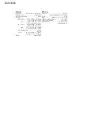
AVX-505 General Power source 14.4 V DC (10.8 - 15.1 V allowable) Grounding system Negative type Max. current consumption 1.5 A Dimensions (DIN) (chassis) ........ 178 (W) × 50 (H)...monitor 156 (W) × 124.6 (H) × 23.5 (D) mm [6-1/8 (W) × 4-7/8 (H) × 7/8 (D) in] Weight 1.6 kg (3.5 lbs) Monitor Screen size 5.5 in dia (effective display area: 83.5 × 111.36 mm) Pixels 224,640 Type TFT active matrix, transmissive type Operation temperature range 10 - +50° C Storage temperature range 20 - +80° C Angle Adjustment 56 ~ 107° (7 steps) intial setting...
AVX-505 General Power source 14.4 V DC (10.8 - 15.1 V allowable) Grounding system Negative type Max. current consumption 1.5 A Dimensions (DIN) (chassis) ........ 178 (W) × 50 (H)...monitor 156 (W) × 124.6 (H) × 23.5 (D) mm [6-1/8 (W) × 4-7/8 (H) × 7/8 (D) in] Weight 1.6 kg (3.5 lbs) Monitor Screen size 5.5 in dia (effective display area: 83.5 × 111.36 mm) Pixels 224,640 Type TFT active matrix, transmissive type Operation temperature range 10 - +50° C Storage temperature range 20 - +80° C Angle Adjustment 56 ~ 107° (7 steps) intial setting...

