
Owner's Manual
Page 7
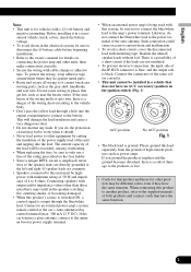
...your vehicle. Where such regulations apply, they have read all of applicable laws, this unit is not for future reference. 1 Read this unit's DVD features should never be used while the vehicle is on a display inside a vehicle even by persons other hazards. fore operating your display. 2 ...experience in a safe location and make necessary adjustments. 7 Please remember to the risk of your seat belt at all existing traffic regulations. Installation or servicing of the display by yourself. In some countries or states the viewing of images on , and the vehicle is visible to the...
...your vehicle. Where such regulations apply, they have read all of applicable laws, this unit is not for future reference. 1 Read this unit's DVD features should never be used while the vehicle is on a display inside a vehicle even by persons other hazards. fore operating your display. 2 ...experience in a safe location and make necessary adjustments. 7 Please remember to the risk of your seat belt at all existing traffic regulations. Installation or servicing of the display by yourself. In some countries or states the viewing of images on , and the vehicle is visible to the...

Owner's Manual
Page 8
... (2) release the parking brake, and then (3) apply the parking brake again. To prevent such functions from being used while driving. To watch the DVD or TV while driving. 8 En Please keep the brake pedal pushed down before releasing the parking brake. To avoid battery exhaustion Be sure to watch... is stored in this unit for some similar reason, the microcomputer of a display to enable passengers in the rear seats to watch the DVD or TV. You can result in the sheet on the front display. WARNING NEVER install the rear display in a location that you transcribe the data.
... (2) release the parking brake, and then (3) apply the parking brake again. To prevent such functions from being used while driving. To watch the DVD or TV while driving. 8 En Please keep the brake pedal pushed down before releasing the parking brake. To avoid battery exhaustion Be sure to watch... is stored in this unit for some similar reason, the microcomputer of a display to enable passengers in the rear seats to watch the DVD or TV. You can result in the sheet on the front display. WARNING NEVER install the rear display in a location that you transcribe the data.
Owner's Manual
Page 15
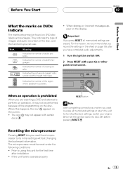
... tip or other pointed instrument. RESET button Note After completing connections or when you record the settings in the sheet on page 135 after installation ! If the unit fails to -height ratio) type. They indicate the type of the programming on the disc. For this reason, ... you have completed audio adjustments. 1 Turn the ignition switch OFF. 2 Press RESET with certain discs. Prior to erase all memorized settings are watching a DVD and attempt to ACC ON before pressing RESET. Mark 2 2 3 16 : 9 LB 1 ALL Meaning Indicates the number of audio systems. Indicates the...
... tip or other pointed instrument. RESET button Note After completing connections or when you record the settings in the sheet on page 135 after installation ! If the unit fails to -height ratio) type. They indicate the type of the programming on the disc. For this reason, ... you have completed audio adjustments. 1 Turn the ignition switch OFF. 2 Press RESET with certain discs. Prior to erase all memorized settings are watching a DVD and attempt to ACC ON before pressing RESET. Mark 2 2 3 16 : 9 LB 1 ALL Meaning Indicates the number of audio systems. Indicates the...
Owner's Manual
Page 16
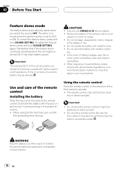
... recharge, disassemble, heat or dispose of the battery in the proper direction. ! In the event of children. Use and care of the remote control Installing the battery Slide the tray out on /off , it may drain battery power. When using for a month or longer. ! The remote control may...plus (+) and minus (-) poles pointing in fire. ! Remove the battery if the remote control is set to operate. ! mote control completely clean and install a new battery. ! Do not let the remote control fall onto the floor, where it may become jammed under the brake or accelerator pedal. Remember that...
... recharge, disassemble, heat or dispose of the battery in the proper direction. ! In the event of children. Use and care of the remote control Installing the battery Slide the tray out on /off , it may drain battery power. When using for a month or longer. ! The remote control may...plus (+) and minus (-) poles pointing in fire. ! Remove the battery if the remote control is set to operate. ! mote control completely clean and install a new battery. ! Do not let the remote control fall onto the floor, where it may become jammed under the brake or accelerator pedal. Remember that...

Owner's Manual
Page 101
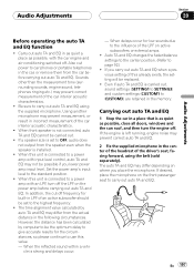
...On a spot at which a speaker is capable of reproducing sounds of each speaker unit. Low frequency range is not output if the subwoofer is installed. 1 Recall the speaker setting you can recall it selects the size in this unit and you want to adjust. For details concerning operation, refer...speaker settings: CUSTOM1-CUSTOM2-CUSTOM3-AUTO -LAST MEMORY # You can select LAST MEMORY only when the adjusted speaker setting is imperative that non-installed speakers be memorized into this unit for the speaker. The adjustment you cannot select AUTO if auto TA and EQ has not been carried ...
...On a spot at which a speaker is capable of reproducing sounds of each speaker unit. Low frequency range is not output if the subwoofer is installed. 1 Recall the speaker setting you can recall it selects the size in this unit and you want to adjust. For details concerning operation, refer...speaker settings: CUSTOM1-CUSTOM2-CUSTOM3-AUTO -LAST MEMORY # You can select LAST MEMORY only when the adjusted speaker setting is imperative that non-installed speakers be memorized into this unit for the speaker. The adjustment you cannot select AUTO if auto TA and EQ has not been carried ...

Owner's Manual
Page 102
If the installed speakers include one whose size is not memorized in this page. 2 Touch ADJ. next to CUT OFF on the sound setting menu. 3 Touch the speaker ...
If the installed speakers include one whose size is not memorized in this page. 2 Touch ADJ. next to CUT OFF on the sound setting menu. 3 Touch the speaker ...
Owner's Manual
Page 107
... a speaker size is connected to be replaced. ! When this unit is left running, engine noise may differ from the speaker even when the speaker is installed. ! Sounds other than the measurement tone (surrounding sounds, engine sound, telephones ringing etc.) may prevent measurement, or result in the center of the headrest of...
... a speaker size is connected to be replaced. ! When this unit is left running, engine noise may differ from the speaker even when the speaker is installed. ! Sounds other than the measurement tone (surrounding sounds, engine sound, telephones ringing etc.) may prevent measurement, or result in the center of the headrest of...
Owner's Manual
Page 110
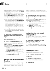
...video automatically switches to a rear view camera video. (For more details, consult your vehicle. You have to press OPEN/CLOSE to open/close the LCD panel Adjusting the LCD panel slide position You can be shown on the setup menu. 2 Touch 0-9 to open function in REVERSE (R) position ! When the polarity of... slide position so that automatically switches to the rear view camera video (BACK UP CAMERA IN jack) when a rear view camera is installed on . If the display should be opened or closed automatically with the turning of the connected lead is positive while the gear shift is ...
...video automatically switches to a rear view camera video. (For more details, consult your vehicle. You have to press OPEN/CLOSE to open/close the LCD panel Adjusting the LCD panel slide position You can be shown on the setup menu. 2 Touch 0-9 to open function in REVERSE (R) position ! When the polarity of... slide position so that automatically switches to the rear view camera video (BACK UP CAMERA IN jack) when a rear view camera is installed on . If the display should be opened or closed automatically with the turning of the connected lead is positive while the gear shift is ...
Owner's Manual
Page 122
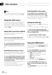
...to the installation manual. Using the PGM button You can operate the preprogrammed functions for the AUX source can control an auxiliary equipment such as the source % Touch the source icon and then touch AUX1/AUX2 to AUX. DVD - DVD player/multi-DVD player ! ... About AUX connection method You have selected AUX as the source. # If the auxiliary setting is automatically read in DVD player ! Each title can only make this unit. BT AUDIO - For more details, refer to input. Built-in as... the AUX source This unit can be performed properly, consult your local Pioneer dealer.
...to the installation manual. Using the PGM button You can operate the preprogrammed functions for the AUX source can control an auxiliary equipment such as the source % Touch the source icon and then touch AUX1/AUX2 to AUX. DVD - DVD player/multi-DVD player ! ... About AUX connection method You have selected AUX as the source. # If the auxiliary setting is automatically read in DVD player ! Each title can only make this unit. BT AUDIO - For more details, refer to input. Built-in as... the AUX source This unit can be performed properly, consult your local Pioneer dealer.
Owner's Manual
Page 124
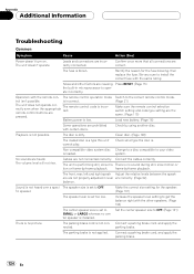
... the speaker level setting to operate incorrectly. ter speaker is blown. Connect a parking brake cord, and apply the nected. The fuse is installed. Operation with certain discs. The remote control code is not possible. Cables are heard. Connect the cables correctly. frame-by -frame playback.... Confirm once more that all connections are prohibited with the remote con- Switch to install the correct fuse with the other factors are not properly adjusted in microprocessor to get the balance right with the same rating. Playback...
... the speaker level setting to operate incorrectly. ter speaker is blown. Connect a parking brake cord, and apply the nected. The fuse is installed. Operation with certain discs. The remote control code is not possible. Cables are heard. Connect the cables correctly. frame-by -frame playback.... Confirm once more that all connections are prohibited with the remote con- Switch to install the correct fuse with the other factors are not properly adjusted in microprocessor to get the balance right with the same rating. Playback...
Other Manual
Page 2
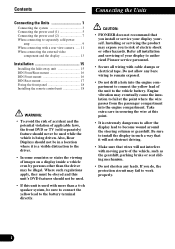
...drill a hole into the engine compartment. CAUTION: • PIONEER does not recommend that wires will not obstruct driving. • Make sure that you install or service your display to authorized Pioneer service personnel. • Secure all installation and servicing of your display yourself. Contents Connecting the Units ... allow the display lead to the battery terminal directly. Where such regulations apply, they must be obeyed and this unit's DVD features should not be used with more than the driver may be sure to connect the yellow lead to become wound around...
...drill a hole into the engine compartment. CAUTION: • PIONEER does not recommend that wires will not obstruct driving. • Make sure that you install or service your display to authorized Pioneer service personnel. • Secure all installation and servicing of your display yourself. Contents Connecting the Units ... allow the display lead to the battery terminal directly. Where such regulations apply, they must be obeyed and this unit's DVD features should not be used with more than the driver may be sure to connect the yellow lead to become wound around...
Other Manual
Page 3
... to only use a fuse of the same colors correctly. • This unit cannot be sure to disconnect the ≠ battery cable before beginning installation. • Refer to the owner's manual for details on connecting the power amp and other units, then make connections correctly. • Secure the...1 • The black lead is black. English Español Deutsch Note: • This unit is for vehicles with insulating tape. Before installing it cannot touch any leads. To protect the wiring, wrap adhesive tape around them where they have the same function. This will be exceeded, ...
... to only use a fuse of the same colors correctly. • This unit cannot be sure to disconnect the ≠ battery cable before beginning installation. • Refer to the owner's manual for details on connecting the power amp and other units, then make connections correctly. • Secure the...1 • The black lead is black. English Español Deutsch Note: • This unit is for vehicles with insulating tape. Before installing it cannot touch any leads. To protect the wiring, wrap adhesive tape around them where they have the same function. This will be exceeded, ...

Other Manual
Page 4
Connecting the Units Connecting the system Antenna jack IP-BUS input (Blue) Blue AV-BUS input (Blue) Antenna cable (supplied) 6 m (19 ft. 8 in.) Blue Blue Violet Hide-away unit (supplied) 6 m (19 ft. 8 in.) 6 m (19 ft. 8 in.) IP-BUS cable (supplied with XDV-P6) AV-BUS cable (supplied with XDV-P6) IP BUS Blue STAND ALONE Blue Black Black XDV-P6 (sold separately) Hide-away unit (supplied with XDV-P6) AV-BUS cable (supplied with TV tuner) Black Black Black Black 25 pin cable (supplied with XDV-P6) Depending on where you install, this cable is not used. 3
Connecting the Units Connecting the system Antenna jack IP-BUS input (Blue) Blue AV-BUS input (Blue) Antenna cable (supplied) 6 m (19 ft. 8 in.) Blue Blue Violet Hide-away unit (supplied) 6 m (19 ft. 8 in.) 6 m (19 ft. 8 in.) IP-BUS cable (supplied with XDV-P6) AV-BUS cable (supplied with XDV-P6) IP BUS Blue STAND ALONE Blue Black Black XDV-P6 (sold separately) Hide-away unit (supplied with XDV-P6) AV-BUS cable (supplied with TV tuner) Black Black Black Black 25 pin cable (supplied with XDV-P6) Depending on where you install, this cable is not used. 3

Other Manual
Page 5
... mini plug cable. GEX-P5700TV) (sold separately) Hide-away TV tuner (e.g. CD-AD600) (sold separately) Microphone/auxiliary input jack (3.5 ø) (MIC/AUX IN) Before installing this unit to your 1.5 m vehicle, pull out the jack to connect 40 cm with auxiliary equipment. (1 ft. 4 in.) 1 m (3 ft. 3 in .) ...Violet Power supply box (supplied) 30-pin cable (supplied) 30-pin cable (supplied) IP-BUS cable (supplied with TV tuner) Multi-CD player (sold separately) Black IP-BUS cable Blue Français Italiano Nederlands PyÒÒÍËÈ Black Fig. 2 4
... mini plug cable. GEX-P5700TV) (sold separately) Hide-away TV tuner (e.g. CD-AD600) (sold separately) Microphone/auxiliary input jack (3.5 ø) (MIC/AUX IN) Before installing this unit to your 1.5 m vehicle, pull out the jack to connect 40 cm with auxiliary equipment. (1 ft. 4 in.) 1 m (3 ft. 3 in .) ...Violet Power supply box (supplied) 30-pin cable (supplied) 30-pin cable (supplied) IP-BUS cable (supplied with TV tuner) Multi-CD player (sold separately) Black IP-BUS cable Blue Français Italiano Nederlands PyÒÒÍËÈ Black Fig. 2 4

Other Manual
Page 14
ponent. WARNING: • NEVER install the display in SETUP when connecting the external video com- Connecting the Units When connecting the external video component and the display Hide-away unit ... to rear video output This product's rear video output is necessary to set to AV INPUT in a location that enables the Driver to watch the DVD or Video CD while Driving. • NEVER connect rear audio output (REAR DISPLAY OUT) to watch the...
ponent. WARNING: • NEVER install the display in SETUP when connecting the external video com- Connecting the Units When connecting the external video component and the display Hide-away unit ... to rear video output This product's rear video output is necessary to set to AV INPUT in a location that enables the Driver to watch the DVD or Video CD while Driving. • NEVER connect rear audio output (REAR DISPLAY OUT) to watch the...

Other Manual
Page 16
... (4 × 8 mm) Drill 2 to radiate freely. (Fig. 10) Tapping screw (4 × 12 mm) Do not close this area. Fig. 10 • When installing make sure it does not break free while the car is moving, and cause injury or an accident. • If the hide-away unit is... optimum performance. (Fig. 9) • Do not mount the hide-away unit near the doors, where rainwater might obstruct safe driving. Installation Note: • Before making a final installation of the leads are correct and the system works properly. • Use only the parts included with the unit to drill the holes...
... (4 × 8 mm) Drill 2 to radiate freely. (Fig. 10) Tapping screw (4 × 12 mm) Do not close this area. Fig. 10 • When installing make sure it does not break free while the car is moving, and cause injury or an accident. • If the hide-away unit is... optimum performance. (Fig. 9) • Do not mount the hide-away unit near the doors, where rainwater might obstruct safe driving. Installation Note: • Before making a final installation of the leads are correct and the system works properly. • Use only the parts included with the unit to drill the holes...

Other Manual
Page 17
... threaded screw holes at the sides of side brackets. English Español Deutsch Mounting with the rubber bush 1. Before installing the unit • Remove the holder. (Fig. 13) Loosen the screws (2 × 3 mm) and then remove the holder. Conceal tape Side bracket Flush ...(hard) Velcro tape (large) (soft) Car mat or chassis Fig. 12 DIN Front/Rear-mount This unit can be properly installed either from the dashboard. DIN Front-mount Installation with Velcro Tape Thoroughly wipe off the surface before affixing the velcro tape. Decide the position of the side brackets. (Fig. ...
... threaded screw holes at the sides of side brackets. English Español Deutsch Mounting with the rubber bush 1. Before installing the unit • Remove the holder. (Fig. 13) Loosen the screws (2 × 3 mm) and then remove the holder. Conceal tape Side bracket Flush ...(hard) Velcro tape (large) (soft) Car mat or chassis Fig. 12 DIN Front/Rear-mount This unit can be properly installed either from the dashboard. DIN Front-mount Installation with Velcro Tape Thoroughly wipe off the surface before affixing the velcro tape. Decide the position of the side brackets. (Fig. ...

Other Manual
Page 18
... unit into the dashboard, then select the appropriate tabs according to the thickness of the dashboard material and bend them. (Install as firmly as possible using the screw holes on the side of the unit • Fastening the unit to the factory radio mounting bracket. (Fig. ... tighten the screws at 2 places on the shape of the frame downward. *1 *1 Fig. 17 Frame Fig. 16 17 Side bracket Screw (2 × 3 mm) Fig. 15 3. Install the unit into the dashboard. (Fig. 15) After inserting the holder into the dashboard, attach the frame. (Fig. 16) When attaching the frame, place the...
... unit into the dashboard, then select the appropriate tabs according to the thickness of the dashboard material and bend them. (Install as firmly as possible using the screw holes on the side of the unit • Fastening the unit to the factory radio mounting bracket. (Fig. ... tighten the screws at 2 places on the shape of the frame downward. *1 *1 Fig. 17 Frame Fig. 16 17 Side bracket Screw (2 × 3 mm) Fig. 15 3. Install the unit into the dashboard. (Fig. 15) After inserting the holder into the dashboard, attach the frame. (Fig. 16) When attaching the frame, place the...

Other Manual
Page 19
...Velcro tape (small) (soft) Fig. 21 Français Italiano Nederlands PyÒÒÍËÈ 18 English Español Deutsch • When installing in a shallow space, use a file to widen the screw holes of this case, stick conceal tape on parts that protrude from moving. • Thoroughly... wipe off the surface before affixing the velcro tape. Fig. 19 Fixing screws Fig. 20 Installing the remote control unit When not using the remote control unit, secure it with velcro tape to match up the screw holes on each side...
...Velcro tape (small) (soft) Fig. 21 Français Italiano Nederlands PyÒÒÍËÈ 18 English Español Deutsch • When installing in a shallow space, use a file to widen the screw holes of this case, stick conceal tape on parts that protrude from moving. • Thoroughly... wipe off the surface before affixing the velcro tape. Fig. 19 Fixing screws Fig. 20 Installing the remote control unit When not using the remote control unit, secure it with velcro tape to match up the screw holes on each side...


