Owner's Manual
Page 3
... 57 Adjusting the response positions of the touch panels (Touch Panel Calibration) 57 Using an AUX source 58 Using an external unit 58 Installation Connecting the units 60 Installation 68 Additional Information Troubleshooting 69 Error messages 71 Understanding messages 74 Indicator list 75 Handling guidelines 76 Compressed audio compatibility (disc, USB) 78...
... 57 Adjusting the response positions of the touch panels (Touch Panel Calibration) 57 Using an AUX source 58 Using an external unit 58 Installation Connecting the units 60 Installation 68 Additional Information Troubleshooting 69 Error messages 71 Understanding messages 74 Indicator list 75 Handling guidelines 76 Compressed audio compatibility (disc, USB) 78...
Owner's Manual
Page 4
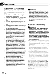
...attempt to the risk of your vehicle. Where such regulations apply, they have read all existing traffic regulations. If you to install or service your display by persons without training and experience in electronic equipment and automotive accessories may be dangerous and could expose ... parking brake is on the front display. Section 01 Precautions IMPORTANT SAFEGUARDS Please read and understood the operating instructions. 5 Do not install the display where it may be illegal. will divert your attention from the safe operation of the vehicle's operating systems or safety ...
...attempt to the risk of your vehicle. Where such regulations apply, they have read all existing traffic regulations. If you to install or service your display by persons without training and experience in electronic equipment and automotive accessories may be dangerous and could expose ... parking brake is on the front display. Section 01 Precautions IMPORTANT SAFEGUARDS Please read and understood the operating instructions. 5 Do not install the display where it may be illegal. will divert your attention from the safe operation of the vehicle's operating systems or safety ...
Owner's Manual
Page 5
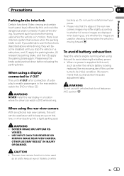
... to V OUT This unit's V OUT is for checking the rear when the vehicle is supplied to this unit returns to its initial condition. WARNING NEVER install the rear display in a safe place, and (1) apply the parking brake, (2) release the parking brake, and then (3) apply the parking brake again. To avoid battery...
... to V OUT This unit's V OUT is for checking the rear when the vehicle is supplied to this unit returns to its initial condition. WARNING NEVER install the rear display in a safe place, and (1) apply the parking brake, (2) release the parking brake, and then (3) apply the parking brake again. To avoid battery...
Owner's Manual
Page 8
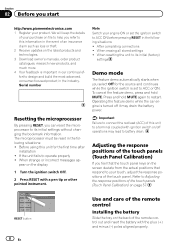
...that the touch panel keys on /off it may lead to your purchase on file to help you select Off for the first time after installation ! Adjusting the response positions of an insurance claim such as loss or theft. 2 Receive updates on page 57. Serial number Resetting the ...When strange or incorrect messages ap- To cancel the feature demo, press and hold MUTE again to Adjusting the response positions of the remote control Installing the battery Slide the tray on the display 1 Turn the ignition switch OFF. 2 Press RESET with ignition switch on the screen deviate from the...
...that the touch panel keys on /off it may lead to your purchase on file to help you select Off for the first time after installation ! Adjusting the response positions of an insurance claim such as loss or theft. 2 Receive updates on page 57. Serial number Resetting the ...When strange or incorrect messages ap- To cancel the feature demo, press and hold MUTE again to Adjusting the response positions of the remote control Installing the battery Slide the tray on the display 1 Turn the ignition switch OFF. 2 Press RESET with ignition switch on the screen deviate from the...
Owner's Manual
Page 9
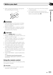
Before you start Section 02 ! There is a danger of children. If the battery leaks, wipe the remote control completely clean and install a new battery. ! peratures or direct sunlight. Use one CR2025 (3 V) lithium battery. ! Before you start WARNING ! Keep the ...out the film protruding from the tray. ! The remote control may not function properly in high tem- En 9 Batteries (battery pack or batteries installed) must not be swallowed, consult a doctor immediately. ! Important ! special handling may become jammed under the brake or accelerator pedal. CAUTION !...
Before you start Section 02 ! There is a danger of children. If the battery leaks, wipe the remote control completely clean and install a new battery. ! peratures or direct sunlight. Use one CR2025 (3 V) lithium battery. ! Before you start WARNING ! Keep the ...out the film protruding from the tray. ! The remote control may not function properly in high tem- En 9 Batteries (battery pack or batteries installed) must not be swallowed, consult a doctor immediately. ! Important ! special handling may become jammed under the brake or accelerator pedal. CAUTION !...
Owner's Manual
Page 54
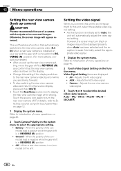
... source icon again to REVERSE (R) and confirm that automatically switches to the rear view camera video (R.C IN) when a rear view camera is installed on the system menu to Auto, the unit will appear reversed. When the polarity of a camera which outputs mirror-reversed images. AV - Adjusts... suitable video signal setting. ! Touch the RearView source icon to this unit Setting the video signal When you set up camera) CAUTION Pioneer recommends the use of the connected lead is positive while the gear shift is in REVERSE (R) position ! When the polarity of menu ...
... source icon again to REVERSE (R) and confirm that automatically switches to the rear view camera video (R.C IN) when a rear view camera is installed on the system menu to Auto, the unit will appear reversed. When the polarity of a camera which outputs mirror-reversed images. AV - Adjusts... suitable video signal setting. ! Touch the RearView source icon to this unit Setting the video signal When you set up camera) CAUTION Pioneer recommends the use of the connected lead is positive while the gear shift is in REVERSE (R) position ! When the polarity of menu ...
Owner's Manual
Page 60
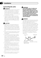
...steering column or gearstick. WARNING ! LIGHT GREEN LEAD AT POWER CON- WARNING ! The black cable is extremely dangerous to allow any cables. Installing or servicing the product may eventually cause the insulation to connect the yellow cable of car's body (Another electronic device in - It is ground... speakers over 50 W (output value) and between 4 W to metal parts of electric shock or other than the driver may fail to authorized Pioneer service personnel. ! CAUTION ! Do not allow the microphone lead to connect the ground wire first. Do not shorten any bare wiring to the ...
...steering column or gearstick. WARNING ! LIGHT GREEN LEAD AT POWER CON- WARNING ! The black cable is extremely dangerous to allow any cables. Installing or servicing the product may eventually cause the insulation to connect the yellow cable of car's body (Another electronic device in - It is ground... speakers over 50 W (output value) and between 4 W to metal parts of electric shock or other than the driver may fail to authorized Pioneer service personnel. ! CAUTION ! Do not allow the microphone lead to connect the ground wire first. Do not shorten any bare wiring to the ...
Owner's Manual
Page 61
...together negative cables of the same color. F O OF T ACC position No ACC position ! To prevent a short-circuit, overheating or malfunction, be installed in order to share the power with metal parts to connect connectors of multiple speakers. ! Place all cables away from hot places, such as the... gear shift and seat rails. - Never cut the insulation of the power cable of this cable to the power terminal of the battery before installation. - Connect this unit in a vehicle without ACC (accessory) position on , control signals are color-coded. Be sure to protect the wiring...
...together negative cables of the same color. F O OF T ACC position No ACC position ! To prevent a short-circuit, overheating or malfunction, be installed in order to share the power with metal parts to connect connectors of multiple speakers. ! Place all cables away from hot places, such as the... gear shift and seat rails. - Never cut the insulation of the power cable of this cable to the power terminal of the battery before installation. - Connect this unit in a vehicle without ACC (accessory) position on , control signals are color-coded. Be sure to protect the wiring...
Owner's Manual
Page 62
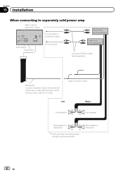
...; Front speaker Front speaker Rear speaker or Subwoofer Perform these connections when using the optional amplifier. Section 15 Installation When connecting to separately sold power amp Rear output or subwoofer output To rear output or subwoofer output Power amp (sold separately) Front output This...
...; Front speaker Front speaker Rear speaker or Subwoofer Perform these connections when using the optional amplifier. Section 15 Installation When connecting to separately sold power amp Rear output or subwoofer output To rear output or subwoofer output Power amp (sold separately) Front output This...
Owner's Manual
Page 63
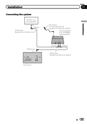
CD-BTB200) (sold separately) Black IP-BUS cable (Supplied with HD Radio tuner) Section 15 Microphone for hands-free phoning (supplied with Bluetooth adapter) En 63 Installation Connecting the system HD Radio tuner (sold separately) Installation IP-BUS input This product Blue Black IP-BUS cable (Supplied with Bluetooth adapter) Bluetooth adapter (e.g.
CD-BTB200) (sold separately) Black IP-BUS cable (Supplied with HD Radio tuner) Section 15 Microphone for hands-free phoning (supplied with Bluetooth adapter) En 63 Installation Connecting the system HD Radio tuner (sold separately) Installation IP-BUS input This product Blue Black IP-BUS cable (Supplied with Bluetooth adapter) Bluetooth adapter (e.g.
Owner's Manual
Page 64
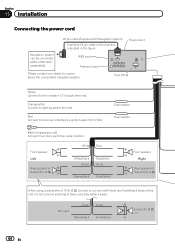
... to the constant 12 V supply terminal. Red Connect to lighting switch terminal. Orange/white Connect to terminal controlled by ignition switch (12 V DC). Section 15 Installation Connecting the power cord Navigation system can be connected (AVIC-U220 (sold separately)). 26 pin cable (Supplied with Violet and Violet/black leads of 70...
... to the constant 12 V supply terminal. Red Connect to lighting switch terminal. Orange/white Connect to terminal controlled by ignition switch (12 V DC). Section 15 Installation Connecting the power cord Navigation system can be connected (AVIC-U220 (sold separately)). 26 pin cable (Supplied with Violet and Violet/black leads of 70...
Owner's Manual
Page 65
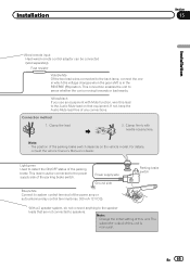
... brake switch depends on that are not connected to speakers. Clamp the lead. 2. The subwoofer output of this unit is moving forwards or backwards. Installation Section 15 Installation Wired remote input Hard-wired remote control adaptor can be connected to the power supply side of the parking brake switch. Fuse resistor Violet...
... brake switch depends on that are not connected to speakers. Clamp the lead. 2. The subwoofer output of this unit is moving forwards or backwards. Installation Section 15 Installation Wired remote input Hard-wired remote control adaptor can be connected to the power supply side of the parking brake switch. Fuse resistor Violet...
Owner's Manual
Page 66
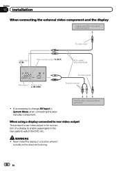
WARNING ! Section 15 Installation When connecting the external video component and the display Display with RCA input jacks (sold separately) To video input Video input (V IN) Rear monitor output (V ... (sold separately) This product Audio inputs (L IN, R IN) To video output To audio outputs ! It is visible to the driver while driving. 66 En Never install the display in System Menu when connecting the external video component.
WARNING ! Section 15 Installation When connecting the external video component and the display Display with RCA input jacks (sold separately) To video input Video input (V IN) Rear monitor output (V ... (sold separately) This product Audio inputs (L IN, R IN) To video output To audio outputs ! It is visible to the driver while driving. 66 En Never install the display in System Menu when connecting the external video component.
Owner's Manual
Page 67
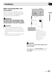
..., connect the one in the REVERSE (R) position. This connection enables the unit to sense whether the car is in which outputs mirror reversed images. Installation Section 15 Installation When connecting with a rear view camera When this product is used with a rear view camera, it is possible to automatically switch from the video...
..., connect the one in the REVERSE (R) position. This connection enables the unit to sense whether the car is in which outputs mirror reversed images. Installation Section 15 Installation When connecting with a rear view camera When this product is used with a rear view camera, it is possible to automatically switch from the video...
Owner's Manual
Page 68
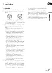
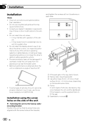
... holes of the bracket, and tighten the screws at an angle of vehicles, this unit where: - cle. - Optimum performance is obtained when the unit is installed at 3 or 4 locations on each side. 1 2 3 4 5 1 If the pawl gets in the way, bend it may cause malfunctions. ! To some ...from hot places such as a re- In such case, use unauthorized parts as this may cause injury to a passenger as near the heater outlet. ! Install this happens, use the supplied frame to the factory radiomounting bracket. it down. 2 Factory radio mounting bracket 3 Use either truss (5 mm × 8...
... holes of the bracket, and tighten the screws at an angle of vehicles, this unit where: - cle. - Optimum performance is obtained when the unit is installed at 3 or 4 locations on each side. 1 2 3 4 5 1 If the pawl gets in the way, bend it may cause malfunctions. ! To some ...from hot places such as a re- In such case, use unauthorized parts as this may cause injury to a passenger as near the heater outlet. ! Install this happens, use the supplied frame to the factory radiomounting bracket. it down. 2 Factory radio mounting bracket 3 Use either truss (5 mm × 8...
Owner's Manual
Page 69
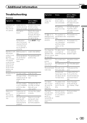
... parking brake. The data could no longer be read during still, slow motion or frameby-frame playback. There is low. The attenuator is turned to install a fuse with this unit. En 69 Leads and con- that is no sound. Battery power is no sound during playback. Try operating with the config...
... parking brake. The data could no longer be read during still, slow motion or frameby-frame playback. There is low. The attenuator is turned to install a fuse with this unit. En 69 Leads and con- that is no sound. Battery power is no sound during playback. Try operating with the config...


