
Owner's Manual
Page 4
... functions Adjusting the response positions of the touch panels (Touch Panel Calibration) 75 Using an AUX source 75 Using an external unit 76 Installation Connecting the units 77 Installation 87 Additional information Troubleshooting 90 Error messages 92 Understanding auto EQ error messages 96 Understanding messages 96 Indicator list 97 Handling guidelines 99...
... functions Adjusting the response positions of the touch panels (Touch Panel Calibration) 75 Using an AUX source 75 Using an external unit 76 Installation Connecting the units 77 Installation 87 Additional information Troubleshooting 90 Error messages 92 Understanding auto EQ error messages 96 Understanding messages 96 Indicator list 97 Handling guidelines 99...

Owner's Manual
Page 5
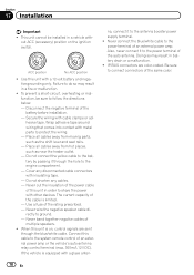
...of any of the vehicle's operating systems or safety features, including air bags, hazard lamp buttons or (iii) impair the driver's ability to install or service your display by persons other hazards. To ensure safe driving WARNING ! To avoid the risk of damage and injury and the potential ...is not for operating procedures and safety information. 3 Pay close attention to wear your seat belt at all times while operating your vehicle. Installation or servicing of the display by persons without training and experience in motion. 10 Never set the volume of your display so high that you...
...of any of the vehicle's operating systems or safety features, including air bags, hazard lamp buttons or (iii) impair the driver's ability to install or service your display by persons other hazards. To ensure safe driving WARNING ! To avoid the risk of damage and injury and the potential ...is not for operating procedures and safety information. 3 Pay close attention to wear your seat belt at all times while operating your vehicle. Installation or servicing of the display by persons without training and experience in motion. 10 Never set the volume of your display so high that you...

Owner's Manual
Page 6
... and/or unlawful if used while the vehicle is in motion, there is an interlock system that do not feature an ACC position. WARNING NEVER install the rear display in a location where the driver can be used as an aid to avoid draining the battery power. ! Do not use the functions...
... and/or unlawful if used while the vehicle is in motion, there is an interlock system that do not feature an ACC position. WARNING NEVER install the rear display in a location where the driver can be used as an aid to avoid draining the battery power. ! Do not use the functions...

Owner's Manual
Page 7
...to provide reasonable protection against harmful interference in conjunction with any other antenna or transmitter. En 7 This transmitter must not be installed and operated keeping the radiator at least 20 cm or more of the following two conditions: (1) this device may not ...equipment complies with FCC/IC radiation exposure limits set forth for help. Reorient or relocate the receiving antenna. - MODEL NO.: AVH-P1400DVD This device complies with the instructions, may cause undesired operation. Operation is no guarantee that may cause harmful interference to the following...
...to provide reasonable protection against harmful interference in conjunction with any other antenna or transmitter. En 7 This transmitter must not be installed and operated keeping the radiator at least 20 cm or more of the following two conditions: (1) this device may not ...equipment complies with FCC/IC radiation exposure limits set forth for help. Reorient or relocate the receiving antenna. - MODEL NO.: AVH-P1400DVD This device complies with the instructions, may cause undesired operation. Operation is no guarantee that may cause harmful interference to the following...
Owner's Manual
Page 10
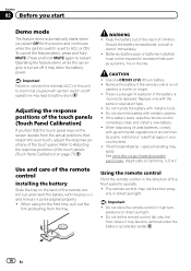
... batteries, comply with ignition switch on the screen deviate from the tray. peratures or direct sunlight. ! Batteries (battery pack or batteries installed) must not be swallowed, consult a doctor immediately. ! There is a danger of children. Important Failure to connect the red lead ... to California, U.S.A.)" Using the remote control Point the remote control in your touch, adjust the response positions of the remote control Installing the battery Slide the tray on page 75. Press and hold MUTE. Use one CR2025 (3 V) lithium battery. ! Use and...
... batteries, comply with ignition switch on the screen deviate from the tray. peratures or direct sunlight. ! Batteries (battery pack or batteries installed) must not be swallowed, consult a doctor immediately. ! There is a danger of children. Important Failure to connect the red lead ... to California, U.S.A.)" Using the remote control Point the remote control in your touch, adjust the response positions of the remote control Installing the battery Slide the tray on page 75. Press and hold MUTE. Use one CR2025 (3 V) lithium battery. ! Use and...

Owner's Manual
Page 30
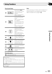
... application for "Pandora"). ! iPhone Data Plan. Limitations: ! compatibility issues with Pioneer. discontinuation of the Pandora music service by connecting your iPod which was installed the Pandora application and starting up the Pandora application. 30 En Current Pandora account... music service not affiliated with future firmware versions of the Pandora application for purposes of allowing your iPod which was installed the Pandora application. 8 12 3 Pandora S.Rtrv Abcdeabcdeabcdeabcde Abcdeabcdeabcdeabcde Abcdeabcdeabcdeabcde Abcdeabcdeabcdeabcde Wed 28 May 12:45 PM 01:...
... application for "Pandora"). ! iPhone Data Plan. Limitations: ! compatibility issues with Pioneer. discontinuation of the Pandora music service by connecting your iPod which was installed the Pandora application and starting up the Pandora application. 30 En Current Pandora account... music service not affiliated with future firmware versions of the Pandora application for purposes of allowing your iPod which was installed the Pandora application. 8 12 3 Pandora S.Rtrv Abcdeabcdeabcdeabcde Abcdeabcdeabcdeabcde Abcdeabcdeabcdeabcde Abcdeabcdeabcdeabcde Wed 28 May 12:45 PM 01:...
Owner's Manual
Page 31
... on the iPod. Note Touch panel keys not listed under Introduction of Pandora operations may appear on page 46. Giving a "Thumbs-up the Pandora application installed on or off. En 31 Refer to Selecting and playing the QuickMix/station list on page 57. Refer to Using sound retriever on the display...
... on the iPod. Note Touch panel keys not listed under Introduction of Pandora operations may appear on page 46. Giving a "Thumbs-up the Pandora application installed on or off. En 31 Refer to Selecting and playing the QuickMix/station list on page 57. Refer to Using sound retriever on the display...
Owner's Manual
Page 67
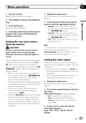
...2 Touch Camera Polarity on the function menu. Setting the rear view camera (back up the rear view camera set up camera) CAUTION Pioneer recommends the use of this setting if the display switches to Auto, the unit will appear reversed. Setting the video signal When you ... IN) when a rear view camera is in REVERSE (R) position ! When the polarity of the connected lead is positive while the shift lever is installed on page 14. After you are displayed. ! ting, move the shift lever to REVERSE (R) and confirm that automatically switches to Introduction of the...
...2 Touch Camera Polarity on the function menu. Setting the rear view camera (back up the rear view camera set up camera) CAUTION Pioneer recommends the use of this setting if the display switches to Auto, the unit will appear reversed. Setting the video signal When you ... IN) when a rear view camera is in REVERSE (R) position ! When the polarity of the connected lead is positive while the shift lever is installed on page 14. After you are displayed. ! ting, move the shift lever to REVERSE (R) and confirm that automatically switches to Introduction of the...

Owner's Manual
Page 75
... to this unit via 3.5 mm plug (4 pole) cable (such as an AUX source and is assigned to AUX. nected to this unit. Refer to Installation on the entire screen. ! After you touch all the marks, the data for adjustment. and 16-point adjustment, in which you make fine-adjustments on... reproduced correctly. % Insert the stereo mini plug into the AUX input jack on the screen deviate from the actual positions that respond to your local Pioneer dealer. 1 Turn the unit off the engine while the data is being saved. 5 Press HOME to proceed to 16-point adjustment. Forcefully pressing the...
... to this unit via 3.5 mm plug (4 pole) cable (such as an AUX source and is assigned to AUX. nected to this unit. Refer to Installation on the entire screen. ! After you touch all the marks, the data for adjustment. and 16-point adjustment, in which you make fine-adjustments on... reproduced correctly. % Insert the stereo mini plug into the AUX input jack on the screen deviate from the actual positions that respond to your local Pioneer dealer. 1 Turn the unit off the engine while the data is being saved. 5 Press HOME to proceed to 16-point adjustment. Forcefully pressing the...

Owner's Manual
Page 77
...car's body (Another electronic device in fire, generation of front seat video should ever occur while the vehicle is ground. Installation Section 17 Installation Connecting the units WARNING ! To avoid the risk of accident and the potential violation of applicable laws, no viewing of smoke...LEAD MAY VIOLATE APPLICABLE LAW AND MAY RESULT IN SERIOUS INJURY OR DAMAGE. When installing this unit. ! CAUTION ! PIONEER does not recommend that cables will not obstruct driving. ! Secure all installation and servicing of this unit or any other than the driver may eventually cause the...
...car's body (Another electronic device in fire, generation of front seat video should ever occur while the vehicle is ground. Installation Section 17 Installation Connecting the units WARNING ! To avoid the risk of accident and the potential violation of applicable laws, no viewing of smoke...LEAD MAY VIOLATE APPLICABLE LAW AND MAY RESULT IN SERIOUS INJURY OR DAMAGE. When installing this unit. ! CAUTION ! PIONEER does not recommend that cables will not obstruct driving. ! Secure all installation and servicing of this unit or any other than the driver may eventually cause the...
Owner's Manual
Page 78
... terminal of this unit is limited. - IP-BUS connectors are sent through the hole to connect connectors of the rating prescribed. - Section 17 Installation Important ! This unit cannot be sure to ground. - F O OF N STAR T ACC position No ACC position ! Use this cable to... Failure to the system remote control of the cable is on the ignition switch. To prevent a short-circuit, overheating or malfunction, be installed in battery drain or a malfunction. ! Disconnect the negative terminal of multiple speakers. ! Secure the wiring with a glass anten- Wrap adhesive...
... terminal of this unit is limited. - IP-BUS connectors are sent through the hole to connect connectors of the rating prescribed. - Section 17 Installation Important ! This unit cannot be sure to ground. - F O OF N STAR T ACC position No ACC position ! Use this cable to... Failure to the system remote control of the cable is on the ignition switch. To prevent a short-circuit, overheating or malfunction, be installed in battery drain or a malfunction. ! Disconnect the negative terminal of multiple speakers. ! Secure the wiring with a glass anten- Wrap adhesive...

Owner's Manual
Page 79
Installation Section 17 Installation En 79
Installation Section 17 Installation En 79
Owner's Manual
Page 80
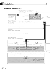
This product Antenna input Fuse (10 A) AUX jack (3.5 ø) (AVH-P4400BH only) Use a mini plug cable to terminal controlled by ignition switch (12 V DC). Red Connect to connect with auxiliary device. Green Green/black Violet .../black leads. Not used. RGB input Navigation system (AVIC-U220(sold separately)) Please contact your dealer to inquire about the connectable navigation unit. Section 17 Installation Connecting the power cord 26 pin cable (Supplied with Violet and Violet/black leads of this unit.
This product Antenna input Fuse (10 A) AUX jack (3.5 ø) (AVH-P4400BH only) Use a mini plug cable to terminal controlled by ignition switch (12 V DC). Red Connect to connect with auxiliary device. Green Green/black Violet .../black leads. Not used. RGB input Navigation system (AVIC-U220(sold separately)) Please contact your dealer to inquire about the connectable navigation unit. Section 17 Installation Connecting the power cord 26 pin cable (Supplied with Violet and Violet/black leads of this unit.

Owner's Manual
Page 81
Installation Section 17 Installation 4 m (13 ft. 1 in.) Microphone (AVH-P4400BH/AVH-P3400BH/AVH-P2400BT only) Microphone input (AVH-P4400BH/AVH-P3400BH/AVH-P2400BT only) Wired remote input Hard-wired remote control adaptor can be connected to the power supply side of this unit. This lead must be ...
Installation Section 17 Installation 4 m (13 ft. 1 in.) Microphone (AVH-P4400BH/AVH-P3400BH/AVH-P2400BT only) Microphone input (AVH-P4400BH/AVH-P3400BH/AVH-P2400BT only) Wired remote input Hard-wired remote control adaptor can be connected to the power supply side of this unit. This lead must be ...
Owner's Manual
Page 82
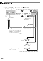
Section 17 Installation When connecting to separately sold power amp Rear output Front output Subwoofer output This product To rear output To front output To subwoofer output Power ...
Section 17 Installation When connecting to separately sold power amp Rear output Front output Subwoofer output This product To rear output To front output To subwoofer output Power ...

Owner's Manual
Page 83
CD-BTB200) (sold separately) Section 17 Installation IP-BUS input Black IP-BUS cable (Supplied with Bluetooth adapter) Connecting the system (for hands-free phoning (supplied with HD Radio tuner) En 83 Installation Connecting the system (for AVH-P1400DVD model) This product Microphone for AVH-P2400BT/AVH-P1400DVD model) This product HD Radio tuner (sold separately) IP-BUS input IP-BUS cable (Supplied with Bluetooth adapter) Bluetooth adapter (e.g.
CD-BTB200) (sold separately) Section 17 Installation IP-BUS input Black IP-BUS cable (Supplied with Bluetooth adapter) Connecting the system (for hands-free phoning (supplied with HD Radio tuner) En 83 Installation Connecting the system (for AVH-P1400DVD model) This product Microphone for AVH-P2400BT/AVH-P1400DVD model) This product HD Radio tuner (sold separately) IP-BUS input IP-BUS cable (Supplied with Bluetooth adapter) Bluetooth adapter (e.g.

Owner's Manual
Page 84
Section 17 Installation When connecting with optional CD-IU201V cable This product USB input iPod with video capabilities (sold separately) 2 m (6 ft. 7 in .) USB cable (Supplied with this unit for AVH-P4400BH. Sold separately for other models.) Interface cable (CD-IU201V) (sold separately) Dock connector AUX input (AUX) 1.5 m (4 ft. 11 in .) 84 En
Section 17 Installation When connecting with optional CD-IU201V cable This product USB input iPod with video capabilities (sold separately) 2 m (6 ft. 7 in .) USB cable (Supplied with this unit for AVH-P4400BH. Sold separately for other models.) Interface cable (CD-IU201V) (sold separately) Dock connector AUX input (AUX) 1.5 m (4 ft. 11 in .) 84 En

Owner's Manual
Page 85
WARNING ! Never install the display in the system menu when connecting the external video component. En 85 Refer to Setting AV input on page 64. Display with RCA ... is necessary to change AV Input in a location where it is visible to the driver while driving. Installation Section 17 When connecting the external video component and the display External video component (sold separately) Installation Audio inputs (L IN, R IN) To audio outputs To video output Video input (V IN) RCA cables (sold separately...
WARNING ! Never install the display in the system menu when connecting the external video component. En 85 Refer to Setting AV input on page 64. Display with RCA ... is necessary to change AV Input in a location where it is visible to the driver while driving. Installation Section 17 When connecting the external video component and the display External video component (sold separately) Installation Audio inputs (L IN, R IN) To audio outputs To video output Video input (V IN) RCA cables (sold separately...

Owner's Manual
Page 86
... to keep an eye on page 67. For details, refer to Basic operations on this unit automatically switches to the rear view image. Section 17 Installation When connecting with a rear view camera When the shift lever is switched to REVERSE (R), the display on page 14. Do not use a camera which the...
... to keep an eye on page 67. For details, refer to Basic operations on this unit automatically switches to the rear view image. Section 17 Installation When connecting with a rear view camera When the shift lever is switched to REVERSE (R), the display on page 14. Do not use a camera which the...

Owner's Manual
Page 87
...with the screw holes of the bracket, and tighten the screws at an angle of holes or other modifications to safely operate the vehicle. ! When installing, to the factory radiomounting bracket. it may cause injury to a passenger as a result of the unit % Fastening the unit to ensure proper ...heat dispersal when using the screw holes on each side. Do not install the display where it overheats. Install this unit away from hot places such as this unit cannot be damaged if it may cause malfunctions. ! Optimum performance is ...
...with the screw holes of the bracket, and tighten the screws at an angle of holes or other modifications to safely operate the vehicle. ! When installing, to the factory radiomounting bracket. it may cause injury to a passenger as a result of the unit % Fastening the unit to ensure proper ...heat dispersal when using the screw holes on each side. Do not install the display where it overheats. Install this unit away from hot places such as this unit cannot be damaged if it may cause malfunctions. ! Optimum performance is ...


