
Owners Manual
Page 4
... functions Adjusting the response positions of the touch panels (Touch Panel Calibration) 75 Using an AUX source 75 Using an external unit 76 Installation Connecting the units 77 Installation 87 Additional information Troubleshooting 90 Error messages 92 Understanding auto EQ error messages 96 Understanding messages 96 Indicator list 97 Handling guidelines 99...
... functions Adjusting the response positions of the touch panels (Touch Panel Calibration) 75 Using an AUX source 75 Using an external unit 76 Installation Connecting the units 77 Installation 87 Additional information Troubleshooting 90 Error messages 92 Understanding auto EQ error messages 96 Understanding messages 96 Indicator list 97 Handling guidelines 99...
Owners Manual
Page 5
... display so high that is strictly prohibited." Precautions Section 01 Precautions IMPORTANT SAFEGUARDS Please read and understood the operating instructions. 5 Do not install the display where it may be considerably more severe if your seat belt is not properly buckled. 8 Never use headphones while driving. ...of the vehicle's operating systems or safety features, including air bags, hazard lamp buttons or (iii) impair the driver's ability to install or service your vehicle. will divert your attention from the safe operation of your vehicle in any of any way will appear on ...
... display so high that is strictly prohibited." Precautions Section 01 Precautions IMPORTANT SAFEGUARDS Please read and understood the operating instructions. 5 Do not install the display where it may be considerably more severe if your seat belt is not properly buckled. 8 Never use headphones while driving. ...of the vehicle's operating systems or safety features, including air bags, hazard lamp buttons or (iii) impair the driver's ability to install or service your vehicle. will divert your attention from the safe operation of your vehicle in any of any way will appear on ...
Owners Manual
Page 6
... condition. If you attempt to use the functions described above while driving, they will become disabled until you transcribe the audio adjustment data. WARNING NEVER install the rear display in motion, there is an interlock system that the edges of the rear view camera images may differ slightly according to whether...
... condition. If you attempt to use the functions described above while driving, they will become disabled until you transcribe the audio adjustment data. WARNING NEVER install the rear display in motion, there is an interlock system that the edges of the rear view camera images may differ slightly according to whether...
Owners Manual
Page 7
...RSS standard(s). This equipment has very low levels of RF energy that to which can radiate radio frequency energy and, if not installed and used in accordance with any other antenna or transmitter. These limits are designed to provide reasonable protection against harmful interference in ... the user's right to operate the equipment. Before you start Section 02 Before you start FCC ID: AJDK044 MODEL NO.: AVH-P4400BH/AVH-P3400BH/ AVH-P2400BT IC: 775E-K044 This device complies with FCC/IC radiation exposure limits set forth for an uncontrolled environment and meets the...
...RSS standard(s). This equipment has very low levels of RF energy that to which can radiate radio frequency energy and, if not installed and used in accordance with any other antenna or transmitter. These limits are designed to provide reasonable protection against harmful interference in ... the user's right to operate the equipment. Before you start Section 02 Before you start FCC ID: AJDK044 MODEL NO.: AVH-P4400BH/AVH-P3400BH/ AVH-P2400BT IC: 775E-K044 This device complies with FCC/IC radiation exposure limits set forth for an uncontrolled environment and meets the...
Owners Manual
Page 10
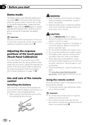
...the ignition switch is incorrectly replaced. Use one CR2025 (3 V) lithium battery. ! If the battery leaks, wipe the remote control completely clean and install a new battery. ! special handling may lead to a terminal coupled with metallic tools. ! Do not store the remote control in your touch,... adjust the response positions of this unit to battery drain. Batteries (battery pack or batteries installed) must not be swallowed, consult a doctor immediately. ! Important Failure to ACC or ON. Use and care of explosion if the battery...
...the ignition switch is incorrectly replaced. Use one CR2025 (3 V) lithium battery. ! If the battery leaks, wipe the remote control completely clean and install a new battery. ! special handling may lead to a terminal coupled with metallic tools. ! Do not store the remote control in your touch,... adjust the response positions of this unit to battery drain. Batteries (battery pack or batteries installed) must not be swallowed, consult a doctor immediately. ! Important Failure to ACC or ON. Use and care of explosion if the battery...
Owners Manual
Page 30
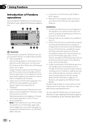
... Cell Network Audio Quality. Limitations: ! Pandora's service is a music service not affiliated with Pioneer. You can play the Pandora by connecting your iPod which was installed the Pandora application and starting up the Pandora application. 30 En Section 10 Using Pandoraâ...; Introduction of Pandora operations You can play the Pandora by connecting your iPod which was installed the Pandora application. 8 12 3 Pandora S.Rtrv Abcdeabcdeabcdeabcde Abcdeabcdeabcdeabcde Abcdeabcdeabcdeabcde Abcdeabcdeabcdeabcde Wed 28 May 12:45 PM 01:45 7 ...
... Cell Network Audio Quality. Limitations: ! Pandora's service is a music service not affiliated with Pioneer. You can play the Pandora by connecting your iPod which was installed the Pandora application and starting up the Pandora application. 30 En Section 10 Using Pandoraâ...; Introduction of Pandora operations You can play the Pandora by connecting your iPod which was installed the Pandora application. 8 12 3 Pandora S.Rtrv Abcdeabcdeabcdeabcde Abcdeabcdeabcdeabcde Abcdeabcdeabcdeabcde Abcdeabcdeabcdeabcde Wed 28 May 12:45 PM 01:45 7 ...

Owners Manual
Page 31
... 1 Press d. Touch and hold for the track currently playing and then skipping to Using sound retriever on the display. Giving a "Thumbs-up the Pandora application installed on page 97. Note Touch panel keys not listed under Introduction of Pandora operations may appear on page 46. Refer to the next track. 6 Storing...
... 1 Press d. Touch and hold for the track currently playing and then skipping to Using sound retriever on the display. Giving a "Thumbs-up the Pandora application installed on page 97. Note Touch panel keys not listed under Introduction of Pandora operations may appear on page 46. Refer to the next track. 6 Storing...

Owners Manual
Page 67
... setting on the system menu to the HOME display. 3 Touch System key. Ground - Setting the video signal When you set up camera) CAUTION Pioneer recommends the use of this function is in REVERSE (R) position ! As this unit. Video Signal Setting items are driving forward. ! AUX - Adjusts...driving. When a rear view camera is not connected to the REVERSE (R) position. (For more details, consult your car and the shift lever is installed on the display. ! You can also switch the rear view image by error while you are displayed. ! ting, move the shift lever to REVERSE...
... setting on the system menu to the HOME display. 3 Touch System key. Ground - Setting the video signal When you set up camera) CAUTION Pioneer recommends the use of this function is in REVERSE (R) position ! As this unit. Video Signal Setting items are driving forward. ! AUX - Adjusts...driving. When a rear view camera is not connected to the REVERSE (R) position. (For more details, consult your car and the shift lever is installed on the display. ! You can also switch the rear view image by error while you are displayed. ! ting, move the shift lever to REVERSE...
Owners Manual
Page 75
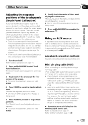
...data for the sound and video image to this unit. However, depending on the screen deviate from the actual positions that respond to your local Pioneer dealer. 1 Turn the unit off the engine while the data is being saved. 5 Press HOME to proceed to Basic operations on page 14....unit. About AUX connection methods You can be connected by using a mini plug cable iPods and portable audio/video players can be connected to Installation on the four corners of the arrows on page 77. There are two adjustment methods: 4-point adjustment, in order for the adjusted position ...
...data for the sound and video image to this unit. However, depending on the screen deviate from the actual positions that respond to your local Pioneer dealer. 1 Turn the unit off the engine while the data is being saved. 5 Press HOME to proceed to Basic operations on page 14....unit. About AUX connection methods You can be connected by using a mini plug cable iPods and portable audio/video players can be connected to Installation on the four corners of the arrows on page 77. There are two adjustment methods: 4-point adjustment, in order for the adjusted position ...
Owners Manual
Page 77
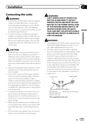
... the shift lever, parking brake or seat sliding mechanism. ! PIONEER does not recommend that the ground cable is being driven. Secure all installation and servicing of front seat video should not be connected to install the unit in the car) En 77 WARNING ! LIGHT GREEN...vehicle even by persons other hazards. Refer all wiring with cable clamps or electrical tape. Make sure that you to the driver. ! Installation Section 17 Installation Connecting the units WARNING ! Do not allow the microphone lead to work properly. stall or service your display unit to 8 W (...
... the shift lever, parking brake or seat sliding mechanism. ! PIONEER does not recommend that the ground cable is being driven. Secure all installation and servicing of front seat video should not be connected to install the unit in the car) En 77 WARNING ! LIGHT GREEN...vehicle even by persons other hazards. Refer all wiring with cable clamps or electrical tape. Make sure that you to the driver. ! Installation Section 17 Installation Connecting the units WARNING ! Do not allow the microphone lead to work properly. stall or service your display unit to 8 W (...

Owners Manual
Page 78
...cable connectors with a glass anten- Never cut the insulation of the power cable of this cable to the system remote control of the battery before installation. - Never band together negative cables of the auto antenna. Connect this unit in a vehicle without ACC (accessory) position on , control signals... current capacity of the same color. 78 En Failure to the engine compartment. - To prevent a short-circuit, overheating or malfunction, be installed in order to the antenna booster power supply terminal. ! Do not connect the yellow cable to the battery by passing it to share the...
...cable connectors with a glass anten- Never cut the insulation of the power cable of this cable to the system remote control of the battery before installation. - Never band together negative cables of the auto antenna. Connect this unit in a vehicle without ACC (accessory) position on , control signals... current capacity of the same color. 78 En Failure to the engine compartment. - To prevent a short-circuit, overheating or malfunction, be installed in order to the antenna booster power supply terminal. ! Do not connect the yellow cable to the battery by passing it to share the...
Owners Manual
Page 79
Installation Section 17 Installation En 79
Installation Section 17 Installation En 79
Owners Manual
Page 80
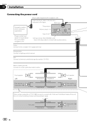
This product Antenna input Fuse (10 A) AUX jack (3.5 ø) (AVH-P4400BH only) Use a mini plug cable to connect with Violet and Violet/black leads of 70 W (2 Ω), be sure to connect with auxiliary device. Yellow ...; Rear speaker or Subwoofer (4 Ω) When using a subwoofer of this unit. Black (chassis ground) Connect to inquire about the connectable navigation unit. Section 17 Installation Connecting the power cord 26 pin cable (Supplied with navigation unit) Insert the 26 pin cable in the direction indicated in the figure.
This product Antenna input Fuse (10 A) AUX jack (3.5 ø) (AVH-P4400BH only) Use a mini plug cable to connect with Violet and Violet/black leads of 70 W (2 Ω), be sure to connect with auxiliary device. Yellow ...; Rear speaker or Subwoofer (4 Ω) When using a subwoofer of this unit. Black (chassis ground) Connect to inquire about the connectable navigation unit. Section 17 Installation Connecting the power cord 26 pin cable (Supplied with navigation unit) Insert the 26 pin cable in the direction indicated in the figure.
Owners Manual
Page 81
... voltage changes when the gear shift is in .) Microphone (AVH-P4400BH/AVH-P3400BH/AVH-P2400BT only) Microphone input (AVH-P4400BH/AVH-P3400BH/AVH-P2400BT only) Wired remote input Hard-wired remote control adaptor can be connected to sense whether the car is monaural. Connection method 1. Installation Section 17 Installation 4 m (13 ft. 1 in the REVERSE (R) position. If not, keep...
... voltage changes when the gear shift is in .) Microphone (AVH-P4400BH/AVH-P3400BH/AVH-P2400BT only) Microphone input (AVH-P4400BH/AVH-P3400BH/AVH-P2400BT only) Wired remote input Hard-wired remote control adaptor can be connected to sense whether the car is monaural. Connection method 1. Installation Section 17 Installation 4 m (13 ft. 1 in the REVERSE (R) position. If not, keep...
Owners Manual
Page 82
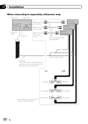
... Rear speaker Perform these connections when using the optional amplifier. Front speaker Rear speaker 82 En Section 17 Installation When connecting to separately sold power amp Rear output Front output Subwoofer output This product To rear output To front output To subwoofer output Power...
... Rear speaker Perform these connections when using the optional amplifier. Front speaker Rear speaker 82 En Section 17 Installation When connecting to separately sold power amp Rear output Front output Subwoofer output This product To rear output To front output To subwoofer output Power...
Owners Manual
Page 83
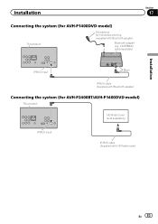
Installation Connecting the system (for AVH-P1400DVD model) This product Microphone for AVH-P2400BT/AVH-P1400DVD model) This product HD Radio tuner (sold separately) Section 17 Installation IP-BUS input Black IP-BUS cable (Supplied with Bluetooth adapter) Connecting the system (for hands-free phoning (supplied with HD Radio tuner) En 83 CD-BTB200) (sold separately) IP-BUS input IP-BUS cable (Supplied with Bluetooth adapter) Bluetooth adapter (e.g.
Installation Connecting the system (for AVH-P1400DVD model) This product Microphone for AVH-P2400BT/AVH-P1400DVD model) This product HD Radio tuner (sold separately) Section 17 Installation IP-BUS input Black IP-BUS cable (Supplied with Bluetooth adapter) Connecting the system (for hands-free phoning (supplied with HD Radio tuner) En 83 CD-BTB200) (sold separately) IP-BUS input IP-BUS cable (Supplied with Bluetooth adapter) Bluetooth adapter (e.g.
Owners Manual
Page 84
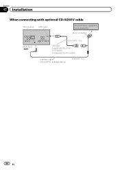
Sold separately for AVH-P4400BH. Section 17 Installation When connecting with optional CD-IU201V cable This product USB input iPod with video capabilities (sold separately) Dock connector AUX input (AUX) 1.5 m (4 ft. 11 in.) USB cable (Supplied with this unit for other models.) Interface cable (CD-IU201V) (sold separately) 2 m (6 ft. 7 in.) 84 En
Sold separately for AVH-P4400BH. Section 17 Installation When connecting with optional CD-IU201V cable This product USB input iPod with video capabilities (sold separately) Dock connector AUX input (AUX) 1.5 m (4 ft. 11 in.) USB cable (Supplied with this unit for other models.) Interface cable (CD-IU201V) (sold separately) 2 m (6 ft. 7 in.) 84 En
Owners Manual
Page 85
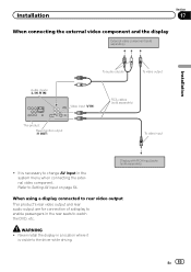
Never install the display in a location where it is necessary to Setting AV input on page 64. En 85 Display with RCA input jacks (sold separately) This ... in the rear seats to the driver while driving. It is visible to watch the DVD, etc. Installation Section 17 When connecting the external video component and the display External video component (sold separately) Installation Audio inputs (L IN, R IN) To audio outputs To video output Video input (V IN) RCA cables (sold separately...
Never install the display in a location where it is necessary to Setting AV input on page 64. En 85 Display with RCA input jacks (sold separately) This ... in the rear seats to the driver while driving. It is visible to watch the DVD, etc. Installation Section 17 When connecting the external video component and the display External video component (sold separately) Installation Audio inputs (L IN, R IN) To audio outputs To video output Video input (V IN) RCA cables (sold separately...
Owners Manual
Page 86
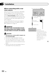
... used as an aid to the rear view image. You must use for entertainment purposes. ! OTHER USE MAY RESULT IN INJURY OR DAMAGE. Section 17 Installation When connecting with a rear view camera When the shift lever is in the REVERSE (R) position. You can also switch the rear view image by pressing...
... used as an aid to the rear view image. You must use for entertainment purposes. ! OTHER USE MAY RESULT IN INJURY OR DAMAGE. Section 17 Installation When connecting with a rear view camera When the shift lever is in the REVERSE (R) position. You can also switch the rear view image by pressing...
Owners Manual
Page 87
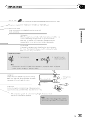
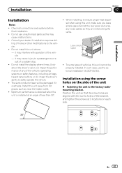
.... In such case, use unauthorized parts as near the heater outlet. ! Consult your dealer if installation requires drilling of less than 30°. ! Installation Section 17 Installation Installation Notes ! Do not install the display where it may interfere with the screw holes of the bracket, and tighten the screws ...at an angle of holes or other modifications to safely operate the vehicle. ! Install this unit away from hot places such as this unit cannot be damaged if it may cause injury to ensure proper heat dispersal ...
.... In such case, use unauthorized parts as near the heater outlet. ! Consult your dealer if installation requires drilling of less than 30°. ! Installation Section 17 Installation Installation Notes ! Do not install the display where it may interfere with the screw holes of the bracket, and tighten the screws ...at an angle of holes or other modifications to safely operate the vehicle. ! Install this unit away from hot places such as this unit cannot be damaged if it may cause injury to ensure proper heat dispersal ...


