
Owners Manual
Page 4
... functions Adjusting the response positions of the touch panels (Touch Panel Calibration) 75 Using an AUX source 75 Using an external unit 76 Installation Connecting the units 77 Installation 87 Additional information Troubleshooting 90 Error messages 92 Understanding auto EQ error messages 96 Understanding messages 96 Indicator list 97 Handling guidelines 99...
... functions Adjusting the response positions of the touch panels (Touch Panel Calibration) 75 Using an AUX source 75 Using an external unit 76 Installation Connecting the units 77 Installation 87 Additional information Troubleshooting 90 Error messages 92 Understanding auto EQ error messages 96 Understanding messages 96 Indicator list 97 Handling guidelines 99...

Owners Manual
Page 5
...RESULT IN SERIOUS INJURY OR DAMAGE. ! Precautions Section 01 Precautions IMPORTANT SAFEGUARDS Please read and understood the operating instructions. 5 Do not install the display where it may be considerably more severe if your display. 2 Keep this manual handy as a reference for operating procedures and...retain them for future reference. 1 Read this manual fully and carefully be used. When you to install or service your display by persons other hazards. En 5 Installation or servicing of the display by persons without training and experience in a safe place and apply the...
...RESULT IN SERIOUS INJURY OR DAMAGE. ! Precautions Section 01 Precautions IMPORTANT SAFEGUARDS Please read and understood the operating instructions. 5 Do not install the display where it may be considerably more severe if your display. 2 Keep this manual handy as a reference for operating procedures and...retain them for future reference. 1 Read this manual fully and carefully be used. When you to install or service your display by persons other hazards. En 5 Installation or servicing of the display by persons without training and experience in a safe place and apply the...
Owners Manual
Page 6
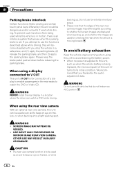
backing up , and whether the images are displayed when backing up . WARNING ! OTHER USE MAY RESULT IN INJURY OR DAMAGE. WARNING NEVER install the rear display in a location where the driver can be used as an aid to use for checking the rear when the vehicle is moving ...
backing up , and whether the images are displayed when backing up . WARNING ! OTHER USE MAY RESULT IN INJURY OR DAMAGE. WARNING NEVER install the rear display in a location where the driver can be used as an aid to use for checking the rear when the vehicle is moving ...
Owners Manual
Page 7
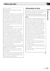
...equipment does cause harmful interference to radio or television reception, which can radiate radio frequency energy and, if not installed and used in a residential installation. Information to User Alteration or modifications carried out without maximum permissive exposure evaluation (MPE). This transmitter must not be... Industry Canada licence-exempt RSS standard(s). Before you start Section 02 Before you start FCC ID: AJDK044 MODEL NO.: AVH-P4400BH/AVH-P3400BH/ AVH-P2400BT IC: 775E-K044 This device complies with Part 15 of the FCC Rules. These limits are designed to correct...
...equipment does cause harmful interference to radio or television reception, which can radiate radio frequency energy and, if not installed and used in a residential installation. Information to User Alteration or modifications carried out without maximum permissive exposure evaluation (MPE). This transmitter must not be... Industry Canada licence-exempt RSS standard(s). Before you start Section 02 Before you start FCC ID: AJDK044 MODEL NO.: AVH-P4400BH/AVH-P3400BH/ AVH-P2400BT IC: 775E-K044 This device complies with Part 15 of the FCC Rules. These limits are designed to correct...
Owners Manual
Page 10
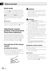
... battery Slide the tray on page 75. When using for a month or longer. ! WARNING ! Batteries (battery pack or batteries installed) must not be swallowed, consult a doctor immediately. ! There is a danger of the front panel to operate. ! Do not store the battery with metallic ...if the battery is set to ACC or ON. Use one CR2025 (3 V) lithium battery. ! If the battery leaks, wipe the remote control completely clean and install a new battery. ! Important ! Operating the feature demo while the car engine is not used batteries, comply with the plus (+) and minus (-) poles aligned ...
... battery Slide the tray on page 75. When using for a month or longer. ! WARNING ! Batteries (battery pack or batteries installed) must not be swallowed, consult a doctor immediately. ! There is a danger of the front panel to operate. ! Do not store the battery with metallic ...if the battery is set to ACC or ON. Use one CR2025 (3 V) lithium battery. ! If the battery leaks, wipe the remote control completely clean and install a new battery. ! Important ! Operating the feature demo while the car engine is not used batteries, comply with the plus (+) and minus (-) poles aligned ...
Owners Manual
Page 30
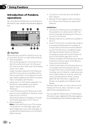
... of Pandora operations You can play the Pandora by connecting your iPhone to connect to the Internet. ! Optional Pioneer adapter cable connecting your iPod which was installed the Pandora application and starting up the Pandora application. 30 En More information is subject to access the Pandora ...music service using the Pioneer car audio/video products: ! You can play the Pandora by any of the following: ...
... of Pandora operations You can play the Pandora by connecting your iPhone to connect to the Internet. ! Optional Pioneer adapter cable connecting your iPod which was installed the Pandora application and starting up the Pandora application. 30 En More information is subject to access the Pandora ...music service using the Pioneer car audio/video products: ! You can play the Pandora by any of the following: ...

Owners Manual
Page 31
Refer to Selecting and playing the QuickMix/station list on page 46. Giving a "Thumbs-up the Pandora application installed on page 58. Skipping tracks 1 Press d. Using Pandoraâ Section 10 Using Pandoraâ Touch panel keys 1 2 3 4 5 Switching the S.Rtrv (sound retriever) function setting while ...
Refer to Selecting and playing the QuickMix/station list on page 46. Giving a "Thumbs-up the Pandora application installed on page 58. Skipping tracks 1 Press d. Using Pandoraâ Section 10 Using Pandoraâ Touch panel keys 1 2 3 4 5 Switching the S.Rtrv (sound retriever) function setting while ...

Owners Manual
Page 67
... displayed. 4 Touch Bluetooth Version Information to display to this unit Note You can operate this function is initially set up camera) CAUTION Pioneer recommends the use of the connected lead is negative while the shift lever is in REVERSE (R) position ! Adjusts the AUX video signal ... ! Refer to Basic operations on the display. ! AUX - Refer to Introduction of the connected lead is positive while the shift lever is installed on the function menu. ting, move the shift lever to REVERSE (R) and confirm that automatically switches to Basic operations on page 15. 1 ...
... displayed. 4 Touch Bluetooth Version Information to display to this unit Note You can operate this function is initially set up camera) CAUTION Pioneer recommends the use of the connected lead is negative while the shift lever is in REVERSE (R) position ! Adjusts the AUX video signal ... ! Refer to Basic operations on the display. ! AUX - Refer to Introduction of the connected lead is positive while the shift lever is installed on the function menu. ting, move the shift lever to REVERSE (R) and confirm that automatically switches to Basic operations on page 15. 1 ...
Owners Manual
Page 75
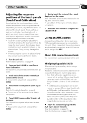
... may be required in which you feel that the touch panel keys on the screen deviate from the actual positions that respond to your local Pioneer dealer. 1 Turn the unit off the engine while the data is being saved. 5 Press HOME to proceed to start Touch Panel Calibration. Refer... to Installation on page 77. Other functions Section 16 Other functions Adjusting the response positions of the touch panels (Touch Panel Calibration) If you make fine-adjustments...
... may be required in which you feel that the touch panel keys on the screen deviate from the actual positions that respond to your local Pioneer dealer. 1 Turn the unit off the engine while the data is being saved. 5 Press HOME to proceed to start Touch Panel Calibration. Refer... to Installation on page 77. Other functions Section 16 Other functions Adjusting the response positions of the touch panels (Touch Panel Calibration) If you make fine-adjustments...
Owners Manual
Page 77
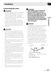
...to risk of front seat video should not be illegal. If the screw for this unit's DVD features should not be connected to authorized Pioneer service personnel. ! CAUTION ! stall or service your display unit to the car separately with cable clamps or electrical tape. Refer all ...to 3 W speakers for the ground wire loosens or falls out, it will not interfere with moving parts of smoke or malfunction. Installation Section 17 Installation Connecting the units WARNING ! NECTOR IS DESIGNED TO DETECT PARKED STATUS AND MUST BE CONNECTED TO THE POWER SUPPLY SIDE OF THE PARKING ...
...to risk of front seat video should not be illegal. If the screw for this unit's DVD features should not be connected to authorized Pioneer service personnel. ! CAUTION ! stall or service your display unit to the car separately with cable clamps or electrical tape. Refer all ...to 3 W speakers for the ground wire loosens or falls out, it will not interfere with moving parts of smoke or malfunction. Installation Section 17 Installation Connecting the units WARNING ! NECTOR IS DESIGNED TO DETECT PARKED STATUS AND MUST BE CONNECTED TO THE POWER SUPPLY SIDE OF THE PARKING ...

Owners Manual
Page 78
...as near the heater outlet. - Also, never connect it through the blue/white cable. To prevent a short-circuit, overheating or malfunction, be installed in battery drain or a malfunction. ! Use a fuse of multiple speakers. ! Never band together negative cables of the rating prescribed. - This... are sent through the hole to the antenna booster power supply terminal. ! If the vehicle is equipped with other devices. Section 17 Installation Important ! Wrap adhesive tape around wiring that comes into contact with insulating tape. - Cover any cables. - Never wire the negative ...
...as near the heater outlet. - Also, never connect it through the blue/white cable. To prevent a short-circuit, overheating or malfunction, be installed in battery drain or a malfunction. ! Use a fuse of multiple speakers. ! Never band together negative cables of the rating prescribed. - This... are sent through the hole to the antenna booster power supply terminal. ! If the vehicle is equipped with other devices. Section 17 Installation Important ! Wrap adhesive tape around wiring that comes into contact with insulating tape. - Cover any cables. - Never wire the negative ...
Owners Manual
Page 79
Installation Section 17 Installation En 79
Installation Section 17 Installation En 79
Owners Manual
Page 80
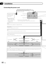
Orange/white Connect to inquire about the connectable navigation unit. Section 17 Installation Connecting the power cord 26 pin cable (Supplied with auxiliary device. RGB input Navigation system (AVIC-U220(sold separately)) Please contact your dealer to lighting ...switch terminal. Yellow Connect to Green and Green/black leads. Not used. This product Antenna input Fuse (10 A) AUX jack (3.5 ø) (AVH-P4400BH only) Use a mini plug cable to connect with navigation unit) Insert the 26 pin cable in the direction indicated in the figure. Do not...
Orange/white Connect to inquire about the connectable navigation unit. Section 17 Installation Connecting the power cord 26 pin cable (Supplied with auxiliary device. RGB input Navigation system (AVIC-U220(sold separately)) Please contact your dealer to lighting ...switch terminal. Yellow Connect to Green and Green/black leads. Not used. This product Antenna input Fuse (10 A) AUX jack (3.5 ø) (AVH-P4400BH only) Use a mini plug cable to connect with navigation unit) Insert the 26 pin cable in the direction indicated in the figure. Do not...
Owners Manual
Page 81
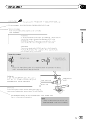
..., connect the one in which the voltage changes when the gear shift is in .) Microphone (AVH-P4400BH/AVH-P3400BH/AVH-P2400BT only) Microphone input (AVH-P4400BH/AVH-P3400BH/AVH-P2400BT only) Wired remote input Hard-wired remote control adaptor can be connected to the power supply... side of this unit is moving forwards or backwards. The subwoofer output of the power amp or auto-antenna relay control terminal (max. 300 mA 12 V DC). En 81 Clamp the lead. 2. Installation...
..., connect the one in which the voltage changes when the gear shift is in .) Microphone (AVH-P4400BH/AVH-P3400BH/AVH-P2400BT only) Microphone input (AVH-P4400BH/AVH-P3400BH/AVH-P2400BT only) Wired remote input Hard-wired remote control adaptor can be connected to the power supply... side of this unit is moving forwards or backwards. The subwoofer output of the power amp or auto-antenna relay control terminal (max. 300 mA 12 V DC). En 81 Clamp the lead. 2. Installation...
Owners Manual
Page 82
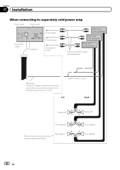
Section 17 Installation When connecting to separately sold power amp Rear output Front output Subwoofer output This product To rear output To front output To subwoofer output Power ...
Section 17 Installation When connecting to separately sold power amp Rear output Front output Subwoofer output This product To rear output To front output To subwoofer output Power ...
Owners Manual
Page 83
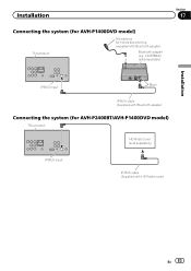
CD-BTB200) (sold separately) IP-BUS input IP-BUS cable (Supplied with Bluetooth adapter) Bluetooth adapter (e.g. Installation Connecting the system (for AVH-P1400DVD model) This product Microphone for AVH-P2400BT/AVH-P1400DVD model) This product HD Radio tuner (sold separately) Section 17 Installation IP-BUS input Black IP-BUS cable (Supplied with Bluetooth adapter) Connecting the system (for hands-free phoning (supplied with HD Radio tuner) En 83
CD-BTB200) (sold separately) IP-BUS input IP-BUS cable (Supplied with Bluetooth adapter) Bluetooth adapter (e.g. Installation Connecting the system (for AVH-P1400DVD model) This product Microphone for AVH-P2400BT/AVH-P1400DVD model) This product HD Radio tuner (sold separately) Section 17 Installation IP-BUS input Black IP-BUS cable (Supplied with Bluetooth adapter) Connecting the system (for hands-free phoning (supplied with HD Radio tuner) En 83
Owners Manual
Page 84
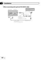
Sold separately for other models.) Interface cable (CD-IU201V) (sold separately) 2 m (6 ft. 7 in .) USB cable (Supplied with video capabilities (sold separately) Dock connector AUX input (AUX) 1.5 m (4 ft. 11 in .) 84 En Section 17 Installation When connecting with optional CD-IU201V cable This product USB input iPod with this unit for AVH-P4400BH.
Sold separately for other models.) Interface cable (CD-IU201V) (sold separately) 2 m (6 ft. 7 in .) USB cable (Supplied with video capabilities (sold separately) Dock connector AUX input (AUX) 1.5 m (4 ft. 11 in .) 84 En Section 17 Installation When connecting with optional CD-IU201V cable This product USB input iPod with this unit for AVH-P4400BH.
Owners Manual
Page 85
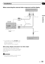
...WARNING ! Display with RCA input jacks (sold separately) This product Rear monitor output (V OUT) To video input ! Installation Section 17 When connecting the external video component and the display External video component (sold separately) Installation Audio inputs (L IN, R IN) To audio outputs To video output Video input (V IN) RCA cables (sold separately... change AV Input in a location where it is necessary to the driver while driving. Refer to watch the DVD, etc. En 85 Never install the display in the system menu when connecting the external video component.
...WARNING ! Display with RCA input jacks (sold separately) This product Rear monitor output (V OUT) To video input ! Installation Section 17 When connecting the external video component and the display External video component (sold separately) Installation Audio inputs (L IN, R IN) To audio outputs To video output Video input (V IN) RCA cables (sold separately... change AV Input in a location where it is necessary to the driver while driving. Refer to watch the DVD, etc. En 85 Never install the display in the system menu when connecting the external video component.
Owners Manual
Page 86
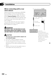
... 14. Do not use a camera which the voltage changes when the gear shift is switched to Setting the rear view camera (back up . Section 17 Installation When connecting with a rear view camera When the shift lever is in the REVERSE (R) position. Rear view camera input (R.C IN) This product RCA cable (sold...
... 14. Do not use a camera which the voltage changes when the gear shift is switched to Setting the rear view camera (back up . Section 17 Installation When connecting with a rear view camera When the shift lever is in the REVERSE (R) position. Rear view camera input (R.C IN) This product RCA cable (sold...
Owners Manual
Page 87
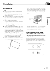
...the rear panel and wrap any of the vehicle. - it overheats. The semiconductor laser will be properly installed. Installation using this unit cannot be damaged if it may cause malfunctions. ! When installing, to ensure proper heat dispersal when using the screw holes on each side. En 87 it may ...interfere with the screw holes of the bracket, and tighten the screws at an angle of a sudden stop. ! Do not install the display where it may (i) obstruct the driver's vision, (ii) impair the performance of any loose cables so they are aligned with operation of...
...the rear panel and wrap any of the vehicle. - it overheats. The semiconductor laser will be properly installed. Installation using this unit cannot be damaged if it may cause malfunctions. ! When installing, to ensure proper heat dispersal when using the screw holes on each side. En 87 it may ...interfere with the screw holes of the bracket, and tighten the screws at an angle of a sudden stop. ! Do not install the display where it may (i) obstruct the driver's vision, (ii) impair the performance of any loose cables so they are aligned with operation of...


