
Operating Instructions
Page 1
... diffèrent d'un pays à l'autre. For customers living in Japanese. Si vous vivez au Japon, reportez-vous aux instructions en japonais. Plasma Display Écran à plasma PDP-507CMX PDP-607CMX Operating Instructions Mode d'emploi Contents related to system specifications, power requirements, accessories, and other information differ with respect to the instructions written in...
... diffèrent d'un pays à l'autre. For customers living in Japanese. Si vous vivez au Japon, reportez-vous aux instructions en japonais. Plasma Display Écran à plasma PDP-507CMX PDP-607CMX Operating Instructions Mode d'emploi Contents related to system specifications, power requirements, accessories, and other information differ with respect to the instructions written in...

Operating Instructions
Page 3
... assuming that it useful in the future. Note for purchasing this PIONEER product. i En PIONEER cannot assume liabilities for damage caused by qualified personnel with enough skill and competence. Always have an installation specialist or your Plasma Display, please read the "Safety Precautions" and these "Operating Instructions" ..., modification or a natural disaster. Keep this manual to the customer and explain to the customer how to operate the Plasma Display properly. You will know how to handle the product. Before using your dealer install and set up the product.
... assuming that it useful in the future. Note for purchasing this PIONEER product. i En PIONEER cannot assume liabilities for damage caused by qualified personnel with enough skill and competence. Always have an installation specialist or your Plasma Display, please read the "Safety Precautions" and these "Operating Instructions" ..., modification or a natural disaster. Keep this manual to the customer and explain to the customer how to operate the Plasma Display properly. You will know how to handle the product. Before using your dealer install and set up the product.
Operating Instructions
Page 6
... assistance. and you wish to locate the nearest Pioneer Authorized Independent Service Company, or if you wish to the following address: Pioneer Electronics of the FCC Rules. English Safety Precautions FEDERAL COMMUNICATIONS COMMISSION DECLARATION OF CONFORMITY This device complies with Video Card Model Number: PDP-507CMX/PDP-607CMX (Plasma Display) PDA-5003/PDA-5004 (Video Card) Product...
... assistance. and you wish to locate the nearest Pioneer Authorized Independent Service Company, or if you wish to the following address: Pioneer Electronics of the FCC Rules. English Safety Precautions FEDERAL COMMUNICATIONS COMMISSION DECLARATION OF CONFORMITY This device complies with Video Card Model Number: PDP-507CMX/PDP-607CMX (Plasma Display) PDA-5003/PDA-5004 (Video Card) Product...
Operating Instructions
Page 7
...Proceeding 3 How to use this manual 3 Checking supplied accessories 5 Part Names and Functions 6 Main unit 6 Remote control unit 7 Connection panel (PDP-507CMX 9 Connection panel (PDP-607CMX 10 Installation and Connections 11 Installation of the unit 11 Connection to a personal computer 13 Audio connections 14 Power cord connection 15 How...status 20 Changing screen size 21 Enlarging one part of the screen (POINT ZOOM 22 Multiscreen display 23 Automatic power-off (POWER MANAGEMENT 24 PICTURE/SCREEN Adjustment 25 PICTURE adjustment 25 Adjusting screen POSITION, CLOCK, and PHASE
...Proceeding 3 How to use this manual 3 Checking supplied accessories 5 Part Names and Functions 6 Main unit 6 Remote control unit 7 Connection panel (PDP-507CMX 9 Connection panel (PDP-607CMX 10 Installation and Connections 11 Installation of the unit 11 Connection to a personal computer 13 Audio connections 14 Power cord connection 15 How...status 20 Changing screen size 21 Enlarging one part of the screen (POINT ZOOM 22 Multiscreen display 23 Automatic power-off (POWER MANAGEMENT 24 PICTURE/SCREEN Adjustment 25 PICTURE adjustment 25 Adjusting screen POSITION, CLOCK, and PHASE
Operating Instructions
Page 8
...Pioneer. Cards used in the expansion slots should be manufactured or recommended by the inclusion of features making the display even more compatible with thinner, lighter, high-endurance design - Broader installation possibilities with your computer. PDP-507CMX: While producing a large 50" screen image, the display...newly developed Wide Plasma Panel The new wide high-precision plasma panel (1365x768 / 16:9) pushes the envelope of previous high-luminance panels, producing brighter, clearer images with higher contrast. ¶ ES Slot interface for enhanced potential The display is provided ...
...Pioneer. Cards used in the expansion slots should be manufactured or recommended by the inclusion of features making the display even more compatible with thinner, lighter, high-endurance design - Broader installation possibilities with your computer. PDP-507CMX: While producing a large 50" screen image, the display...newly developed Wide Plasma Panel The new wide high-precision plasma panel (1365x768 / 16:9) pushes the envelope of previous high-luminance panels, producing brighter, clearer images with higher contrast. ¶ ES Slot interface for enhanced potential The display is provided ...

Operating Instructions
Page 9
...taken out of the box and it has been confirmed that would seem most logical for correct operation of the Plasma Display with its connected components. The section "System Settings" starting on page 17 covers the on page 6 to become acquainted with the... section "Installation and Connections" starting on -screen settings necessary for someone setting up to the more complex operations associated with adjusting the Plasma Display picture to match the requirements of specific components and personal preferences. Before Proceeding 3 En English Before Proceeding How to use this manual ...
...taken out of the box and it has been confirmed that would seem most logical for correct operation of the Plasma Display with its connected components. The section "System Settings" starting on page 17 covers the on page 6 to become acquainted with the... section "Installation and Connections" starting on -screen settings necessary for someone setting up to the more complex operations associated with adjusting the Plasma Display picture to match the requirements of specific components and personal preferences. Before Proceeding 3 En English Before Proceeding How to use this manual ...

Operating Instructions
Page 10
...is performed correctly or not. These Operating Instructions will be considered typical images; When the Plasma Display controls include equivalent buttons to confirm whether the operation is described in practice, depending on the screen item displayed and its proper operating order. Before Proceeding 4 En some difference will refer to the ... are provided to allow you to those buttons found on the remote control unit, the commands can be performed on the main Plasma Display itself. The examples are an example of those found only on the main unit as well.
...is performed correctly or not. These Operating Instructions will be considered typical images; When the Plasma Display controls include equivalent buttons to confirm whether the operation is described in practice, depending on the screen item displayed and its proper operating order. Before Proceeding 4 En some difference will refer to the ... are provided to allow you to those buttons found on the remote control unit, the commands can be performed on the main Plasma Display itself. The examples are an example of those found only on the main unit as well.
Operating Instructions
Page 12
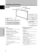
...SCREEN SIZE (') button Except when menu screen is displayed, this button operates to change the screen size. 0 VOL +/- (}/]) buttons When not indicated for adjusting the sound volume (pages 19 and 20). VOL + 89 0 PDP-507CMX 1 STANDBY ON 23 PDP-607CMX 31 Main unit 1 Remote control sensor Point ... the level of light inside the viewing room; English Part Names and Functions Main unit Main unit 4 (PDP-507CMX) 4 (PDP-607CMX) Operation panel on -screen menu (pages 17 to 36). 7 DISPLAY/SET button Use to confirm onscreen menu selections, and to change settings (pages 17 to [AUTO] (page...
...SCREEN SIZE (') button Except when menu screen is displayed, this button operates to change the screen size. 0 VOL +/- (}/]) buttons When not indicated for adjusting the sound volume (pages 19 and 20). VOL + 89 0 PDP-507CMX 1 STANDBY ON 23 PDP-607CMX 31 Main unit 1 Remote control sensor Point ... the level of light inside the viewing room; English Part Names and Functions Main unit Main unit 4 (PDP-507CMX) 4 (PDP-607CMX) Operation panel on -screen menu (pages 17 to 36). 7 DISPLAY/SET button Use to confirm onscreen menu selections, and to change settings (pages 17 to [AUTO] (page...
Operating Instructions
Page 13
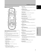
...;/3/2) buttons Use to navigate menu screens and to adjust various settings on the unit (pages 17 to 36). 6 SUB INPUT button During multi-screen display, use the remote control unit in a location subject to direct sunlight, heat radiation from a heater, or in the subscreen (page 36). @ ...SWAP button During multi-screen display, use this button to switch between main screen and subscreen (page 23). # PIP SHIFT button When using computer signal input, automatically sets the [POSITION...
...;/3/2) buttons Use to navigate menu screens and to adjust various settings on the unit (pages 17 to 36). 6 SUB INPUT button During multi-screen display, use the remote control unit in a location subject to direct sunlight, heat radiation from a heater, or in the subscreen (page 36). @ ...SWAP button During multi-screen display, use this button to switch between main screen and subscreen (page 23). # PIP SHIFT button When using computer signal input, automatically sets the [POSITION...

Operating Instructions
Page 14
...rays discharged from the unit and within a 30 angle on the front panel of the main unit. Designated batteries Please use batteries other component that is operable up to the picture displayed. Inserting the batteries in the remote control unit While pressing down lightly,... m (23 feet) 30° 30° Remote Sensor If you are objects placed between it and the display. ¶ Operational distance will differ according to 7 m from the Plasma Display, hampering reception of time, remove the batteries and store them separately. When disposing of used batteries, please comply...
...rays discharged from the unit and within a 30 angle on the front panel of the main unit. Designated batteries Please use batteries other component that is operable up to the picture displayed. Inserting the batteries in the remote control unit While pressing down lightly,... m (23 feet) 30° 30° Remote Sensor If you are objects placed between it and the display. ¶ Operational distance will differ according to 7 m from the Plasma Display, hampering reception of time, remove the batteries and store them separately. When disposing of used batteries, please comply...
Operating Instructions
Page 15
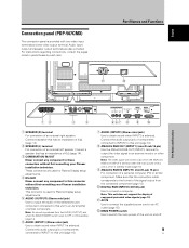
... consulting your Pioneer installation technician. Connect a speaker that has an impedance of 6 Ω (page 14). 2 SPEAKER (L) terminal For connection of an external right speaker. Make sure that has an impedance of the unit on and off or in parentheses by each item. English Connection panel (PDP-507CMX) The connection panel is used for Plasma Display setup adjustments...
... consulting your Pioneer installation technician. Connect a speaker that has an impedance of 6 Ω (page 14). 2 SPEAKER (L) terminal For connection of an external right speaker. Make sure that has an impedance of the unit on and off or in parentheses by each item. English Connection panel (PDP-507CMX) The connection panel is used for Plasma Display setup adjustments...
Operating Instructions
Page 16
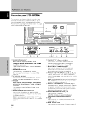
...output from the connected component (page 13). 0 DIGITAL RGB (INPUT2) (DVI-D jack) Use to this connector without first consulting your Pioneer installation technician. Connect a speaker that the connection made corresponds to the format of 6 Ω (page 14). 4 RS-232C ...of an external left speaker. English Part Names and Functions Connection panel (PDP-607CMX) The connection panel is selected. This connector is selected. Audio input/ output and speaker output terminals are used for Plasma Display setup adjustments. 2 SPEAKER (R) terminal For connection of components ...
...output from the connected component (page 13). 0 DIGITAL RGB (INPUT2) (DVI-D jack) Use to this connector without first consulting your Pioneer installation technician. Connect a speaker that the connection made corresponds to the format of 6 Ω (page 14). 4 RS-232C ...of an external left speaker. English Part Names and Functions Connection panel (PDP-607CMX) The connection panel is selected. This connector is selected. Audio input/ output and speaker output terminals are used for Plasma Display setup adjustments. 2 SPEAKER (R) terminal For connection of components ...

Operating Instructions
Page 17
...be a stable, flat, and even surface. English Français Installation and Connections Installation of the unit Installation using the optional PIONEER stand or other mounting brackets ÷ Please be sure to request installation or mounting of this unit by a professional technician possessing... mounting brackets designated by holding the rear handles in the manner shown. The failure to take appropriate measures to move the Plasma Display by Pioneer. Wall-mount installation of this unit. ÷ The installation location selected should not be removed or reattached by anyone other...
...be a stable, flat, and even surface. English Français Installation and Connections Installation of the unit Installation using the optional PIONEER stand or other mounting brackets ÷ Please be sure to request installation or mounting of this unit by a professional technician possessing... mounting brackets designated by holding the rear handles in the manner shown. The failure to take appropriate measures to move the Plasma Display by Pioneer. Wall-mount installation of this unit. ÷ The installation location selected should not be removed or reattached by anyone other...
Operating Instructions
Page 19
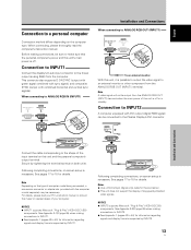
... setup is necessary. Note Depending on this unit is possible to output the video signal to 43) for information regarding signals and display formats supported by INPUT1. Notes ¶ Use a DVI-D 24-pin (digital only) cable for the connection. ¶ This unit does...completing connections, on both units. See Appendix 2-2/2 (page 45) when making connections to INPUT2. ¶ See Appendix 1 (pages 43 to the Plasma Display's DVI connector. This connector also supports G ON SYNC (output with green signal combined with sync signal), and composite SYNC (output with the computer or...
... setup is necessary. Note Depending on this unit is possible to output the video signal to 43) for information regarding signals and display formats supported by INPUT1. Notes ¶ Use a DVI-D 24-pin (digital only) cable for the connection. ¶ This unit does...completing connections, on both units. See Appendix 2-2/2 (page 45) when making connections to INPUT2. ¶ See Appendix 1 (pages 43 to the Plasma Display's DVI connector. This connector also supports G ON SYNC (output with green signal combined with sync signal), and composite SYNC (output with the computer or...

Operating Instructions
Page 20
...wire cores of the selected video input is equipped with speaker output terminals for connection to the audio inputs on the Plasma Display, causing operation to protrude excessively, since they may touch each other component. English Installation and Connections Audio connections Before ...will produce excessive load on this unit. Connecting the speakers This unit is output from the component connected to INPUT1, to the Plasma Display's AUDIO (INPUT1) stereo mini jack (L/R). This will result in their terminals. Audio connections for component (computer) connected to INPUT1...
...wire cores of the selected video input is equipped with speaker output terminals for connection to the audio inputs on the Plasma Display, causing operation to protrude excessively, since they may touch each other component. English Installation and Connections Audio connections Before ...will produce excessive load on this unit. Connecting the speakers This unit is output from the component connected to INPUT1, to the Plasma Display's AUDIO (INPUT1) stereo mini jack (L/R). This will result in their terminals. Audio connections for component (computer) connected to INPUT1...

Operating Instructions
Page 21
.... Wind the audio cable (not supplied) around the ferrite core once, and then fasten the catch. In the event that indicated (AC 100 V to 120 V, 50 Hz/60 Hz) as possible to the unit, first turn off the main unit's power switch, and then disconnect the power cord from its wall...
.... Wind the audio cable (not supplied) around the ferrite core once, and then fasten the catch. In the event that indicated (AC 100 V to 120 V, 50 Hz/60 Hz) as possible to the unit, first turn off the main unit's power switch, and then disconnect the power cord from its wall...

Operating Instructions
Page 22
.... Note Cables can be placed on the ends of the display. 12 Installation and Connections 1 Organize cables together using the 4 holes marked with this unit for bunching cables together. PDP-507CMX Connect the speed clamps using the provided speed clamps. PDP-607CMX To remove speed clamps Using pliers, twist the clamp ...get damaged when removed. 16 En Insert 1 into an appropriate hole on the rear of the unit, then snap 2 into the back of the display. Speed clamps are connected, follow the following steps to route cables. * As viewed from the rear of 1 to the main unit Use the holes...
.... Note Cables can be placed on the ends of the display. 12 Installation and Connections 1 Organize cables together using the 4 holes marked with this unit for bunching cables together. PDP-507CMX Connect the speed clamps using the provided speed clamps. PDP-607CMX To remove speed clamps Using pliers, twist the clamp ...get damaged when removed. 16 En Insert 1 into an appropriate hole on the rear of the unit, then snap 2 into the back of the display. Speed clamps are connected, follow the following steps to route cables. * As viewed from the rear of 1 to the main unit Use the holes...

Operating Instructions
Page 23
...: 3 ENGLISH 2 3 FRANÇAIS 2 3 ESPAÑOL 2 3 ITALIANO 2 3 DEUTSCH 2 LANGUAGE SET SET : ENGLISH MENU EXIT 7 With the desired language displayed, press the SET button. MENU PICTURE SCREEN LANGUAGE ENERGY SAVE TIMER SETTING S C R E E N M G T. AUTO SETUP MODE AUTO FUNCTION PIP DETECT SPLIT FREEZE SET...to change to select [OPTION]. The STANDBY/ON indicator on the front panel will be set to English as the factory default. System Settings MENU 2/3 SET 5/∞ Remote control unit STANDBY/ON DISPLAY MENU / SET INPUT SCREEN SIZE - The selected language will be set ...
...: 3 ENGLISH 2 3 FRANÇAIS 2 3 ESPAÑOL 2 3 ITALIANO 2 3 DEUTSCH 2 LANGUAGE SET SET : ENGLISH MENU EXIT 7 With the desired language displayed, press the SET button. MENU PICTURE SCREEN LANGUAGE ENERGY SAVE TIMER SETTING S C R E E N M G T. AUTO SETUP MODE AUTO FUNCTION PIP DETECT SPLIT FREEZE SET...to change to select [OPTION]. The STANDBY/ON indicator on the front panel will be set to English as the factory default. System Settings MENU 2/3 SET 5/∞ Remote control unit STANDBY/ON DISPLAY MENU / SET INPUT SCREEN SIZE - The selected language will be set ...
Operating Instructions
Page 24
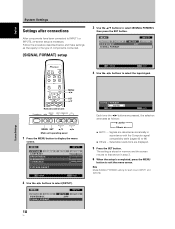
....... Note Make [SIGNAL FORMAT] setting for each input (INPUT1 and INPUT2). VOL + MENU SET 5/∞ 2/3 Main unit operating panel 1 Press the MENU button to exit the menu screen. The setting is necessary. SIGNAL FORMAT INPUT1 SETUP OPTION :OFF 18 En ...SIGNAL FORMAT : AUTO SET SET MENU EXIT Each time the 2/3 buttons are displayed. 5 Press the SET button. English System Settings Settings after connections After components have been connected to select [SETUP]. E N H A N C E ...
....... Note Make [SIGNAL FORMAT] setting for each input (INPUT1 and INPUT2). VOL + MENU SET 5/∞ 2/3 Main unit operating panel 1 Press the MENU button to exit the menu screen. The setting is necessary. SIGNAL FORMAT INPUT1 SETUP OPTION :OFF 18 En ...SIGNAL FORMAT : AUTO SET SET MENU EXIT Each time the 2/3 buttons are displayed. 5 Press the SET button. English System Settings Settings after connections After components have been connected to select [SETUP]. E N H A N C E ...
Operating Instructions
Page 25
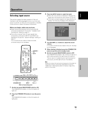
...in the section "Installation and Connections" starting on page 17. Main unit operating panel 1 Set the rear panel MAIN POWER switch to adjust the sound volume. The STANDBY/ON indicator on the following message will be displayed: INPUT1 CAUTION UNSUPPORTED SIGNAL FH: 86.7kHz FV: 88.5Hz - Operation ... connections are made to this unit, this unit in standby mode. 6 Set the rear panel MAIN POWER switch to turn off. ÷ If the input computer signal is not supported by the display, the following pages is not necessary. POL.V: - Note Please do not leave the same...
...in the section "Installation and Connections" starting on page 17. Main unit operating panel 1 Set the rear panel MAIN POWER switch to adjust the sound volume. The STANDBY/ON indicator on the following message will be displayed: INPUT1 CAUTION UNSUPPORTED SIGNAL FH: 86.7kHz FV: 88.5Hz - Operation ... connections are made to this unit, this unit in standby mode. 6 Set the rear panel MAIN POWER switch to turn off. ÷ If the input computer signal is not supported by the display, the following pages is not necessary. POL.V: - Note Please do not leave the same...


