
WVCW384 User Guide
Page 1
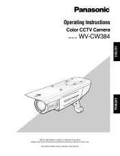
No model number suffix is shown in this manual for future use. FRANÇAIS ENGLISH Operating Instructions Color CCTV Camera WV-CW384 Model No. WV-CW384 Before attempting to connect or operate this product, please read these instructions carefully and save this manual.
No model number suffix is shown in this manual for future use. FRANÇAIS ENGLISH Operating Instructions Color CCTV Camera WV-CW384 Model No. WV-CW384 Before attempting to connect or operate this product, please read these instructions carefully and save this manual.
WVCW384 User Guide
Page 3
......5 Preface ...6 Features ...6 Precautions ...7 Major Operating Controls and Their Functions ...8 Precautions for Installation ...9 Installations/Connections ...10 Preparations ...10 Camera installation ...10 About Setup Menus ...21 Basic operation ...22 Setting Procedures ...23 Language Setup (LANGUAGE SETUP) ...23 1. Shutter Speed ...3 Light Control Mode Setting (ALC) ...24 3. Privacy Zone Setting (PRIVACY ZONE) ...30 13. Camera Identification Setting (CAMERA ID) ...23 2. Gain Control Setting (AGC) ...26 5. Motion Detection Setting (MOTION DET) ...27 9. LED Setting (LED) ......
......5 Preface ...6 Features ...6 Precautions ...7 Major Operating Controls and Their Functions ...8 Precautions for Installation ...9 Installations/Connections ...10 Preparations ...10 Camera installation ...10 About Setup Menus ...21 Basic operation ...22 Setting Procedures ...23 Language Setup (LANGUAGE SETUP) ...23 1. Shutter Speed ...3 Light Control Mode Setting (ALC) ...24 3. Privacy Zone Setting (PRIVACY ZONE) ...30 13. Camera Identification Setting (CAMERA ID) ...23 2. Gain Control Setting (AGC) ...26 5. Motion Detection Setting (MOTION DET) ...27 9. LED Setting (LED) ......
WVCW384 User Guide
Page 5
... CLAIM OR ACTION FOR DAMAGES, BROUGHT BY ANY PERSON OR ORGANIZATION BEING A PHOTOGENIC SUBJECT, DUE TO VIOLATION OF PRIVACY WITH THE RESULT OF THAT SURVEILLANCE-CAMERA'S PICTURE, INCLUDING SAVED DATA, FOR SOME REASON, BECOMES PUBLIC OR IS USED FOR THE PURPOSE OTHER THAN SURVEILLANCE. 5 Disclaimer of Liability THIS PUBLICATION IS PROVIDED...
... CLAIM OR ACTION FOR DAMAGES, BROUGHT BY ANY PERSON OR ORGANIZATION BEING A PHOTOGENIC SUBJECT, DUE TO VIOLATION OF PRIVACY WITH THE RESULT OF THAT SURVEILLANCE-CAMERA'S PICTURE, INCLUDING SAVED DATA, FOR SOME REASON, BECOMES PUBLIC OR IS USED FOR THE PURPOSE OTHER THAN SURVEILLANCE. 5 Disclaimer of Liability THIS PUBLICATION IS PROVIDED...
WVCW384 User Guide
Page 6
...back focus function (ABF) equipped The back focus adjustment can be naturally displayed in the minimum illuminance of focus when changing between color and black-and-white images. High sensitivity achieved thanks to noise reduction function The introduction of low noise circuit design has achieved ... signal processing LSIs. The auto back focus function also allows users to the black-and-white mode at low illuminance. Preface Panasonic's WV-CW384 camera introduces high picture quality by use of SUPER-D3 into the CCD and signal processing circuit has achieved approximately 128 times higher...
...back focus function (ABF) equipped The back focus adjustment can be naturally displayed in the minimum illuminance of focus when changing between color and black-and-white images. High sensitivity achieved thanks to noise reduction function The introduction of low noise circuit design has achieved ... signal processing LSIs. The auto back focus function also allows users to the black-and-white mode at low illuminance. Preface Panasonic's WV-CW384 camera introduces high picture quality by use of SUPER-D3 into the CCD and signal processing circuit has achieved approximately 128 times higher...

WVCW384 User Guide
Page 7
... Parts of the product when using in usage environment. What to observe this product. Immediately turn on the power to warm up the camera. • Images may cause discoloration. Precautions This product has no user-serviceable parts inside. Use a dry cloth to remove, use ... for cleaning, read the caution provided with strong or abrasive detergents. To prevent electric shock, do if OVER HEAT appears on the CCD color filter When continuously shooting a bright light source such as a spot light causes a blooming (light bleeding) or a smear (vertical lines)....
... Parts of the product when using in usage environment. What to observe this product. Immediately turn on the power to warm up the camera. • Images may cause discoloration. Precautions This product has no user-serviceable parts inside. Use a dry cloth to remove, use ... for cleaning, read the caution provided with strong or abrasive detergents. To prevent electric shock, do if OVER HEAT appears on the CCD color filter When continuously shooting a bright light source such as a spot light causes a blooming (light bleeding) or a smear (vertical lines)....

WVCW384 User Guide
Page 8
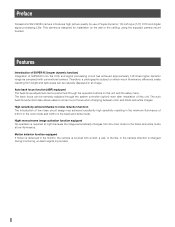
... fixing screws shall be securely tightened. ( page 17) !6 - @0 Operation buttons !6 Up button (UP) !7 Right button (RIGHT) !8 Down button (DOWN) !9 Left button (LEFT) @0 Set button (SET) @1 Camera mount bracket (accessory) @2 Adapter box (accessory) r Focus lock knob Locks the focal point. ( page 16) t Sunshield (accessory) y Front glass u Lens cover Protects the lens. After...
... fixing screws shall be securely tightened. ( page 17) !6 - @0 Operation buttons !6 Up button (UP) !7 Right button (RIGHT) !8 Down button (DOWN) !9 Left button (LEFT) @0 Set button (SET) @1 Camera mount bracket (accessory) @2 Adapter box (accessory) r Focus lock knob Locks the focal point. ( page 16) t Sunshield (accessory) y Front glass u Lens cover Protects the lens. After...
WVCW384 User Guide
Page 9
... to observe this product if it may be installed. The screws and bolts must be sure to install connecting tubes and run the camera cable through the tubes to strong magnetic field or radio waves • Locations where corrosive gas is produced • Locations where it... frozen or direct sunlight. 9 It is not designed for assistance if you are provided to the material and strength of extremely different color temperature (e.g. Piping for cables If this product with an appropriate tightening torque according to fix this product is operated outdoors, be tightened ...
... to observe this product if it may be installed. The screws and bolts must be sure to install connecting tubes and run the camera cable through the tubes to strong magnetic field or radio waves • Locations where corrosive gas is produced • Locations where it... frozen or direct sunlight. 9 It is not designed for assistance if you are provided to the material and strength of extremely different color temperature (e.g. Piping for cables If this product with an appropriate tightening torque according to fix this product is operated outdoors, be tightened ...

WVCW384 User Guide
Page 10
... other factors of the mounting area and the total weight of objects to loosen or tighten the tilting lock screw. Camera installation z Secure the camera to the camera mount bracket The tilt angle is too weak to the horizontal position. 2. Installations/Connections Caution: ONLY CONNECT THIS TO... DC CLASS 2 POWER SUPPLY. plied. Recommended tightening torque M4: 1.6 N·m {1.18 lbf·ft} • Required pull-out capacity of the camera to support the total weight, the area shall be mounted. [Mounting position on a wall are not sup- Note: • Use a hexagonal wrench ...
... other factors of the mounting area and the total weight of objects to loosen or tighten the tilting lock screw. Camera installation z Secure the camera to the camera mount bracket The tilt angle is too weak to the horizontal position. 2. Installations/Connections Caution: ONLY CONNECT THIS TO... DC CLASS 2 POWER SUPPLY. plied. Recommended tightening torque M4: 1.6 N·m {1.18 lbf·ft} • Required pull-out capacity of the camera to support the total weight, the area shall be mounted. [Mounting position on a wall are not sup- Note: • Use a hexagonal wrench ...
WVCW384 User Guide
Page 11
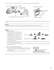
... to waterproof the cables. 4. twice (see the illustration at the connection parts of the power cord and video output cable to the camera mount bracket with tape in length 11 Important: • Ensure that the safety wire is waterproof, but the mount bracket and adapter ...box are not waterproof. Secure the camera to apply waterproof treatment. • Stretch the tape by approx. Twice in a half-overlapping manner. Recommended tightening torque: 0.59 N·m {0....
... to waterproof the cables. 4. twice (see the illustration at the connection parts of the power cord and video output cable to the camera mount bracket with tape in length 11 Important: • Ensure that the safety wire is waterproof, but the mount bracket and adapter ...box are not waterproof. Secure the camera to apply waterproof treatment. • Stretch the tape by approx. Twice in a half-overlapping manner. Recommended tightening torque: 0.59 N·m {0....
WVCW384 User Guide
Page 12
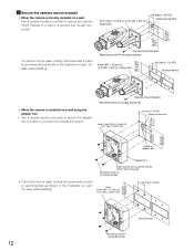
... side is installed on a wall Use 4 screws (locally procured) to secure the camera mount bracket to a wall or a junction box (locally procured). x Secure the camera mount bracket • When the camera is directly installed on a wall using the adapter box 1. Use 4 screws (locally...) 83.5 mm {3-1/4"} 6 mm (W) x 10 mm (L) {1/4" (W) x 3/8" (L)} (long hole) 46 mm {1-13/16"} Junction boxes Camera mount bracket Mounting screw x4 (locally procured) • When the camera is recommended as shown in the illustration at right. (for easy cable passing) Hole 6 mm (W) x 10 mm (H) {1/4" (W) x 13...
... side is installed on a wall Use 4 screws (locally procured) to secure the camera mount bracket to a wall or a junction box (locally procured). x Secure the camera mount bracket • When the camera is directly installed on a wall using the adapter box 1. Use 4 screws (locally...) 83.5 mm {3-1/4"} 6 mm (W) x 10 mm (L) {1/4" (W) x 3/8" (L)} (long hole) 46 mm {1-13/16"} Junction boxes Camera mount bracket Mounting screw x4 (locally procured) • When the camera is recommended as shown in the illustration at right. (for easy cable passing) Hole 6 mm (W) x 10 mm (H) {1/4" (W) x 13...

WVCW384 User Guide
Page 13
...of the adapter box shall be selected so as a wall when the camera mount bracket is connected to the left or right hinges of adapter box. Attach the camera mount bracket to the hinges of the camera mount bracket from being interfered with the 2 mount bracket cover screws (...accessories). Mount bracket cover x2 Camera mount bracket Mount bracket cover screw x2 (M3 x 6) (accessories) ...
...of the adapter box shall be selected so as a wall when the camera mount bracket is connected to the left or right hinges of adapter box. Attach the camera mount bracket to the hinges of the camera mount bracket from being interfered with the 2 mount bracket cover screws (...accessories). Mount bracket cover x2 Camera mount bracket Mount bracket cover screw x2 (M3 x 6) (accessories) ...
WVCW384 User Guide
Page 14
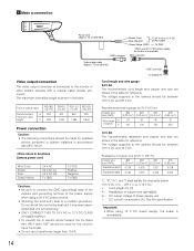
... 24 V AC The recommended cord length and copper wire size are shown in the table. Recommended wire gauge for reference. The voltage supplied to the camera should be between 10.5 V DC and 16 V DC. Important: • When using 12 V DC power supply, the heater is shown in the ... (0.83 mm2) 75 250 12 V DC The recommended resistance and copper wire size are shown in accordance with NEC 725-51. • Wire colors & functions Camera power cord Wire Color Brown Blue Green/Yellow 24 V AC 24 V AC (L) 24 V AC (N) To GND 12 V DC Positive Negative To GND Cautions: • ...
... 24 V AC The recommended cord length and copper wire size are shown in the table. Recommended wire gauge for reference. The voltage supplied to the camera should be between 10.5 V DC and 16 V DC. Important: • When using 12 V DC power supply, the heater is shown in the ... (0.83 mm2) 75 250 12 V DC The recommended resistance and copper wire size are shown in accordance with NEC 725-51. • Wire colors & functions Camera power cord Wire Color Brown Blue Green/Yellow 24 V AC 24 V AC (L) 24 V AC (N) To GND 12 V DC Positive Negative To GND Cautions: • ...
WVCW384 User Guide
Page 15
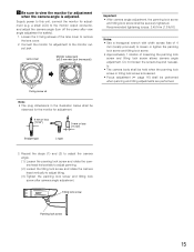
... 1. b Be sure to adjust tilting. (3) Tighten the panning lock screw and tilting lock screw after view angle adjustment for adjustment when the camera angle is loosened. • Focus adjustment ( page 16) shall be securely tightened. Tilting lock screw Panning lock screw 15 Supply power to ...cover. 2. Loosen the 4 fixing screws of loosening the panning lock screw and tilting lock screw allows camera angle adjustment. Do not loosen the screws beyond necessity. • The camera body shall be held when the panning lock screw or tilting lock screw is adjusted. Lens cover ...
... 1. b Be sure to adjust tilting. (3) Tighten the panning lock screw and tilting lock screw after view angle adjustment for adjustment when the camera angle is loosened. • Focus adjustment ( page 16) shall be securely tightened. Tilting lock screw Panning lock screw 15 Supply power to ...cover. 2. Loosen the 4 fixing screws of loosening the panning lock screw and tilting lock screw allows camera angle adjustment. Do not loosen the screws beyond necessity. • The camera body shall be held when the panning lock screw or tilting lock screw is adjusted. Lens cover ...
WVCW384 User Guide
Page 16
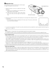
... the focus. • When an auto iris lens is used to automatically follow the variation in the visible light region. Defocus can be performed when camera angle ( page 15) adjustment are performed. Use of "ABF" of "BACK-FOCUS SETUP" in the setup menu ( page 31) allows users to adjust the focus...
... the focus. • When an auto iris lens is used to automatically follow the variation in the visible light region. Defocus can be performed when camera angle ( page 15) adjustment are performed. Use of "ABF" of "BACK-FOCUS SETUP" in the setup menu ( page 31) allows users to adjust the focus...
WVCW384 User Guide
Page 18
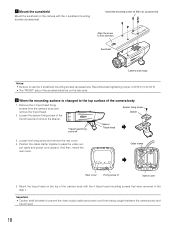
... the rear cover. When the mounting surface is changed to lens direction. Remove the 4 tripod head fixing screws from being caught between the camera body and tripod head. 18 Loosen the fixing screw and remove the rear cover. 4. Position the cable clamp topside to use the 4 sunshield...; Caution shall be on the lens side. . Recommended tightening torque: 0.59 N·m {0.44 lbf·ft} • The "FRONT" side of the camera body with the 4 sunshield mounting screws (accessories). Spacer fixing screw Spacer Tripod head fixing screw x4 Spacer Tripod head 3. Sunshield SDIII...
... the rear cover. When the mounting surface is changed to lens direction. Remove the 4 tripod head fixing screws from being caught between the camera body and tripod head. 18 Loosen the fixing screw and remove the rear cover. 4. Position the cable clamp topside to use the 4 sunshield...; Caution shall be on the lens side. . Recommended tightening torque: 0.59 N·m {0.44 lbf·ft} • The "FRONT" side of the camera body with the 4 sunshield mounting screws (accessories). Spacer fixing screw Spacer Tripod head fixing screw x4 Spacer Tripod head 3. Sunshield SDIII...
WVCW384 User Guide
Page 19
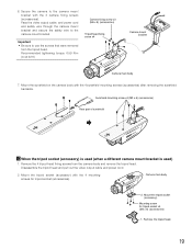
...mounting screw x4 (M3 x 6) (accessories) Rear part of sunshield ⁄0 When the tripod socket (accessory) is used (when a different camera mount bracket is used) 1. Remove the 4 tripod head fixing screws from the tripod head. Mount the tripod socket (accessory) with the 4...Mounting screw for tripod socket (accessories). Recommended tightening torque: 0.59 N·m {0.44 lbf·ft} Camera fixing screw x3 (M4 x 8) (accessories) Tripod head fixing screw x4 Camera mount bracket Camera main body 7. Disassemble the tripod head and pull out the video output cable and power cord. 2. ...
...mounting screw x4 (M3 x 6) (accessories) Rear part of sunshield ⁄0 When the tripod socket (accessory) is used (when a different camera mount bracket is used) 1. Remove the 4 tripod head fixing screws from the tripod head. Mount the tripod socket (accessory) with the 4...Mounting screw for tripod socket (accessories). Recommended tightening torque: 0.59 N·m {0.44 lbf·ft} Camera fixing screw x3 (M4 x 8) (accessories) Tripod head fixing screw x4 Camera mount bracket Camera main body 7. Disassemble the tripod head and pull out the video output cable and power cord. 2. ...

WVCW384 User Guide
Page 20
...head cannot be used indoors. For outdoor installation, use the 4 mounting screws for the following steps. Hook the tip (ring portion) of the camera according to use the camera mount bracket in the accessories. 20 Important: • Be sure to the installation position. Use a safety wire (locally procured) to take ...measures against a fall of the safety wire on the sunshield mounting stud and screw the sunshield to be used . • The camera mount brackets, WV-831 and WV-7010A, and the safety wires, WV-Q140 and WV-Q141, are designed to secure the safety wire.
...head cannot be used indoors. For outdoor installation, use the 4 mounting screws for the following steps. Hook the tip (ring portion) of the camera according to use the camera mount bracket in the accessories. 20 Important: • Be sure to the installation position. Use a safety wire (locally procured) to take ...measures against a fall of the safety wire on the sunshield mounting stud and screw the sunshield to be used . • The camera mount brackets, WV-831 and WV-7010A, and the safety wires, WV-Q140 and WV-Q141, are designed to secure the safety wire.
WVCW384 User Guide
Page 21
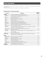
... as a privacy zone. Performs the settings for switching between the color mode and the BW mode. Reset the settings of the white balance adjustment. About Setup Menus Before operation, setup of this camera is an example of the synchronization. Configure the settings relating to ...the default settings. Check the serial number of this camera. Select "ON" or "OFF" to determine whether or not to use the image stabilizer to meet requirements. Adjust the chroma level (color density). Configure the light control method. Select a horizontal resolution mode. ...
... as a privacy zone. Performs the settings for switching between the color mode and the BW mode. Reset the settings of the white balance adjustment. About Setup Menus Before operation, setup of this camera is an example of the synchronization. Configure the settings relating to ...the default settings. Check the serial number of this camera. Select "ON" or "OFF" to determine whether or not to use the image stabilizer to meet requirements. Adjust the chroma level (color density). Configure the light control method. Select a horizontal resolution mode. ...
WVCW384 User Guide
Page 22
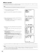
... [RIGHT] button. → The "DISABLE" indication will change into "ENABLE" and the settings will be displayed when the top page is displayed from the camera, move the cursor onto "END" and press the [SET] button. To operate the SETUP menu, switch the "DISABLE" indication to the "ENABLE" indication... the [SET] button. → The setup page of the selected setup item will always be displayed highlighted. 22 END SETUP ENABLE **CAMERA SETUP** 1/2 CAMERA ID OFF ALC ALC SHUTTER OFF AGC ON(HIGH) SENS UP OFF SYNC INT WHITE BAL ATW1 MOTION DET OFF DNR HIGH RESOLUTION HIGH ...
... [RIGHT] button. → The "DISABLE" indication will change into "ENABLE" and the settings will be displayed when the top page is displayed from the camera, move the cursor onto "END" and press the [SET] button. To operate the SETUP menu, switch the "DISABLE" indication to the "ENABLE" indication... the [SET] button. → The setup page of the selected setup item will always be displayed highlighted. 22 END SETUP ENABLE **CAMERA SETUP** 1/2 CAMERA ID OFF ALC ALC SHUTTER OFF AGC ON(HIGH) SENS UP OFF SYNC INT WHITE BAL ATW1 MOTION DET OFF DNR HIGH RESOLUTION HIGH ...
WVCW384 User Guide
Page 23
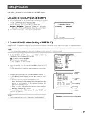
... ALC SHUTTER OFF AGC ON(HIGH) SENS UP OFF SYNC INT WHITE BAL ATW1 MOTION DET OFF DNR HIGH RESOLUTION HIGH BW MODE CAMERA ID 0123456789 ABCDEFGHIJKLM NOPQRSTUVWXYZ SPACE POSI RET TOP END RESET Character Cursor Character Area Command Editing Area Pointer FLOOR 1 Highlighted 23 OFF↓...and press the [SET] button. The default setting is "ENGLISH". Note: • If you change the language selection after the assignment of the camera ID, select "RESET" and press the [SET] button. Move the cursor to display it will be erased. 1. Select a character from the ...
... ALC SHUTTER OFF AGC ON(HIGH) SENS UP OFF SYNC INT WHITE BAL ATW1 MOTION DET OFF DNR HIGH RESOLUTION HIGH BW MODE CAMERA ID 0123456789 ABCDEFGHIJKLM NOPQRSTUVWXYZ SPACE POSI RET TOP END RESET Character Cursor Character Area Command Editing Area Pointer FLOOR 1 Highlighted 23 OFF↓...and press the [SET] button. The default setting is "ENGLISH". Note: • If you change the language selection after the assignment of the camera ID, select "RESET" and press the [SET] button. Move the cursor to display it will be erased. 1. Select a character from the ...


