
Operating Instructions
Page 4
... 7 Accessories 8 Accessories Supplied 8 Remote Control Batteries 8 Connections 9 Speaker connection 9 AC cord connection and fixing, cable fixing 9 Video equipment connection 10 VIDEO and COMPONENT / RGB IN connection... 10 HDMI connection 11 DVI-D IN connection 11 PC Input Terminals connection 12 SERIAL Terminals connection 13 Power ON / OFF 14 Selecting the input signal 16 Basic Controls 17 ASPECT Controls 19 MULTI PIP 20 Digital Zoom 23 On-Screen Menu Displays 24 Adjusting POS. /SIZE 26 PICTURE Adjustments 29 ADVANCED SETTINGS 30 Picture Profiles 31...
... 7 Accessories 8 Accessories Supplied 8 Remote Control Batteries 8 Connections 9 Speaker connection 9 AC cord connection and fixing, cable fixing 9 Video equipment connection 10 VIDEO and COMPONENT / RGB IN connection... 10 HDMI connection 11 DVI-D IN connection 11 PC Input Terminals connection 12 SERIAL Terminals connection 13 Power ON / OFF 14 Selecting the input signal 16 Basic Controls 17 ASPECT Controls 19 MULTI PIP 20 Digital Zoom 23 On-Screen Menu Displays 24 Adjusting POS. /SIZE 26 PICTURE Adjustments 29 ADVANCED SETTINGS 30 Picture Profiles 31...
Operating Instructions
Page 7
... fingernails or other setting-up the power switch for any power supply cord other than that need to the power cable which can cause fire or damage to the internal circuitry. If the Plasma Display will go. • If the plug is detected from rubber or PVC. 7 If water or foreign objects get inside the unit, operating problems may result. • Avoid...
... fingernails or other setting-up the power switch for any power supply cord other than that need to the power cable which can cause fire or damage to the internal circuitry. If the Plasma Display will go. • If the plug is detected from rubber or PVC. 7 If water or foreign objects get inside the unit, operating problems may result. • Avoid...

Operating Instructions
Page 9
... the wall-hanging bracket. If the clamper is locked on speaker installation. Speakers (Optional accessories) 1 Speaker terminal (R) Speaker terminal (L) AC cord connection (see page 14) Red Black While pressing the lever, insert the core wire. 2 Red Black Return the lever. Refer to the speaker's Installation Manual for details on both side snaps hooks Set the tip in a hole. Unplug the AC cord pressing the two knobs. Secure any excess cables with...
... the wall-hanging bracket. If the clamper is locked on speaker installation. Speakers (Optional accessories) 1 Speaker terminal (R) Speaker terminal (L) AC cord connection (see page 14) Red Black While pressing the lever, insert the core wire. 2 Red Black Return the lever. Refer to the speaker's Installation Manual for details on both side snaps hooks Set the tip in a hole. Unplug the AC cord pressing the two knobs. Secure any excess cables with...

Operating Instructions
Page 12
... need to make setting changes to the computer at the time of connection. • Some PC models cannot be displayed properly if the signals exceed 1,200 lines.) • The display resolution is a maximum of 1,440 × 1,080 dots when the aspect mode is set to "4:3", and 1,920 × 1,080 dots when the aspect mode is set the horizontal and vertical scanning frequencies for PC signals which matches the audio output...
... need to make setting changes to the computer at the time of connection. • Some PC models cannot be displayed properly if the signals exceed 1,200 lines.) • The display resolution is a maximum of 1,440 × 1,080 dots when the aspect mode is set to "4:3", and 1,920 × 1,080 dots when the aspect mode is set the horizontal and vertical scanning frequencies for PC signals which matches the audio output...

Operating Instructions
Page 16
... the signals from the equipment which has been connected to the component/RGB input terminals. (see page 49) • In 2 screen display, the same input mode cannot be displayed as "RGB" depending on the unit. • Outputs the sound as follows: PC VIDEO COMPONENT* HDMI DVI VIDEO: Video input terminal in AV IN (VIDEO). PC: PC input terminal in PC IN. * "COMPONENT" may be selected for the main picture and sub picture. • Image retention (image...
... the signals from the equipment which has been connected to the component/RGB input terminals. (see page 49) • In 2 screen display, the same input mode cannot be displayed as "RGB" depending on the unit. • Outputs the sound as follows: PC VIDEO COMPONENT* HDMI DVI VIDEO: Video input terminal in AV IN (VIDEO). PC: PC input terminal in PC IN. * "COMPONENT" may be selected for the main picture and sub picture. • Image retention (image...

Operating Instructions
Page 22
... type of signals displayed on the main picture and depending on the two-screen display mode. • Due to discern details on them satisfactorily. • Following combinations of two input signals cannot be selected for the main picture and sub picture. • The main picture and sub picture are processed by operating the remote control buttons (except for the sub screen, the sub screen audio is set to remain on the sub screen VIDEO...
... type of signals displayed on the main picture and depending on the two-screen display mode. • Due to discern details on them satisfactorily. • Following combinations of two input signals cannot be selected for the main picture and sub picture. • The main picture and sub picture are processed by operating the remote control buttons (except for the sub screen, the sub screen audio is set to remain on the sub screen VIDEO...

Operating Instructions
Page 24
... menu. 24 PICTURE NORMALIZE NORMAL PICTURE MENU PICTURE BRIGHTNESS COLOR TINT SHARPNESS COLOR TEMP COLOR MANAGEMENT ADVANCED SETTINGS STANDARD 25 0 0 0 5 NORMAL OFF MEMORY SAVE MEMORY LOAD MEMORY EDIT (Example: PICTURE menu) Select. Press Press several times. On-Screen Menu Displays 1 Display the menu screen. Set. Press. MENU to return to select. (Example: PICTURE menu) Press several times. Normal Viewing PICTURE SOUND POS. /SIZE SET UP 2 Select the item. Select. Press. 4 Exit the menu. MENU Each time the MENU button is pressed, the menu screen will switch...
... menu. 24 PICTURE NORMALIZE NORMAL PICTURE MENU PICTURE BRIGHTNESS COLOR TINT SHARPNESS COLOR TEMP COLOR MANAGEMENT ADVANCED SETTINGS STANDARD 25 0 0 0 5 NORMAL OFF MEMORY SAVE MEMORY LOAD MEMORY EDIT (Example: PICTURE menu) Select. Press Press several times. On-Screen Menu Displays 1 Display the menu screen. Set. Press. MENU to return to select. (Example: PICTURE menu) Press several times. Normal Viewing PICTURE SOUND POS. /SIZE SET UP 2 Select the item. Select. Press. 4 Exit the menu. MENU Each time the MENU button is pressed, the menu screen will switch...

Operating Instructions
Page 25
... MAIN SDI SOUND OUTPUT 2/2 LEFT CHANNEL RIGHT CHANNEL SOUND OUT LEVEL METER CHANNEL 1 CHANNEL 1 OFF OFF Page 34 SET UP 1/2 SIGNAL SCREENSAVER EXTENDED LIFE SETTINGS INPUT LABEL COMPONENT/RGB-IN SELECT RGB POWER SAVE OFF STANDBY SAVE OFF PC POWER MANAGEMENT OFF DVI-D POWER MANAGEMENT OFF AUTO POWER OFF OSD LANGUAGE OFF ENGLISH (US) SET UP 2/2 MULTI DISPLAY SETUP MULTI PIP SETUP PORTRAIT SETUP SET UP TIMER PRESENT TIME SETUP NETWORK SETUP DISPLAY ORIENTATION LANDSCAPE Page 35-54 MULTI DISPLAY SETUP MULTI DISPLAY SETUP OFF HORIZONTAL...
... MAIN SDI SOUND OUTPUT 2/2 LEFT CHANNEL RIGHT CHANNEL SOUND OUT LEVEL METER CHANNEL 1 CHANNEL 1 OFF OFF Page 34 SET UP 1/2 SIGNAL SCREENSAVER EXTENDED LIFE SETTINGS INPUT LABEL COMPONENT/RGB-IN SELECT RGB POWER SAVE OFF STANDBY SAVE OFF PC POWER MANAGEMENT OFF DVI-D POWER MANAGEMENT OFF AUTO POWER OFF OSD LANGUAGE OFF ENGLISH (US) SET UP 2/2 MULTI DISPLAY SETUP MULTI PIP SETUP PORTRAIT SETUP SET UP TIMER PRESENT TIME SETUP NETWORK SETUP DISPLAY ORIENTATION LANDSCAPE Page 35-54 MULTI DISPLAY SETUP MULTI DISPLAY SETUP OFF HORIZONTAL...
Operating Instructions
Page 26
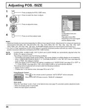
..." Using Remote Control When on the input signal Notes: and the display mode. • Adjustment details are memorized separately for different input signal formats. (Adjustments for component signals are memorized for each frequency.) • If a "Cue" or "Rew" signal from adjust mode. NORMALIZE NORMAL AUTO SETUP H-POS H-SIZE V-POS V-SIZE DOT CLOCK CLOCK PHASE CLAMP POSITION 1:1 PIXEL MODE 0 0 0 0 0 0 0 OFF Note: 4 Press to exit from a VCR or DVD player is received, the picture position will not work , "INVALID...
..." Using Remote Control When on the input signal Notes: and the display mode. • Adjustment details are memorized separately for different input signal formats. (Adjustments for component signals are memorized for each frequency.) • If a "Cue" or "Rew" signal from adjust mode. NORMALIZE NORMAL AUTO SETUP H-POS H-SIZE V-POS V-SIZE DOT CLOCK CLOCK PHASE CLAMP POSITION 1:1 PIXEL MODE 0 0 0 0 0 0 0 OFF Note: 4 Press to exit from a VCR or DVD player is received, the picture position will not work , "INVALID...

Operating Instructions
Page 29
... or right button to the factory settings. 29 STANDARD DYNAMIC MONITOR CINEMA STANDARD For viewing in brighter environments. Press to select the menu to adjust each item. Select the desired level by looking at any time or the ACTION ( ) button is displayed, if either the N button on signal, input and menu setting. DYNAMIC For viewing in standard (evening lighting) environments. Notes: ● When "MONITOR" is grayout. Adjustable menu changes depending on the remote control is...
... or right button to the factory settings. 29 STANDARD DYNAMIC MONITOR CINEMA STANDARD For viewing in brighter environments. Press to select the menu to adjust each item. Select the desired level by looking at any time or the ACTION ( ) button is displayed, if either the N button on signal, input and menu setting. DYNAMIC For viewing in standard (evening lighting) environments. Notes: ● When "MONITOR" is grayout. Adjustable menu changes depending on the remote control is...

Operating Instructions
Page 38
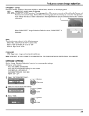
... reduce image retention: SET UP 1/2 SIGNAL SCREENSAVER EXTENDED LIFE SETTINGS INPUT LABEL COMPONENT/RGB-IN SELECT RGB POWER SAVE OFF STANDBY SAVE OFF PC POWER MANAGEMENT OFF DVI-D POWER MANAGEMENT OFF AUTO POWER OFF OSD LANGUAGE OFF ENGLISH (US) EXTENDED LIFE SETTINGS EXPRESS SETTINGS CUSTOM SETTINGS RESET EXTENDED LIFE SETTINGS RECOMMENDED SETTINGS PICTURE MENU PICTURE SIDE BAR ADJUST NANODRIFT SAVER PEAK LIMIT LOCK SETTINGS APPLY TO CURRENT INPUT APPLY TO ALL INPUTS DYNAMIC 30 BRIGHT HIGH MID OFF UNLOCK Set...
... reduce image retention: SET UP 1/2 SIGNAL SCREENSAVER EXTENDED LIFE SETTINGS INPUT LABEL COMPONENT/RGB-IN SELECT RGB POWER SAVE OFF STANDBY SAVE OFF PC POWER MANAGEMENT OFF DVI-D POWER MANAGEMENT OFF AUTO POWER OFF OSD LANGUAGE OFF ENGLISH (US) EXTENDED LIFE SETTINGS EXPRESS SETTINGS CUSTOM SETTINGS RESET EXTENDED LIFE SETTINGS RECOMMENDED SETTINGS PICTURE MENU PICTURE SIDE BAR ADJUST NANODRIFT SAVER PEAK LIMIT LOCK SETTINGS APPLY TO CURRENT INPUT APPLY TO ALL INPUTS DYNAMIC 30 BRIGHT HIGH MID OFF UNLOCK Set...
Operating Instructions
Page 39
... not work in the range where the picture is viewed for each model SIDE BAR ADJUST: BRIGHT NANODRIFT SAVER: HIGH MID PEAK LIMIT: ON 1 Select "EXPRESS SETTINGS". EXTENDED LIFE SETTINGS APPLY TO CURRENT INPUT YES NO 1 select 2 set time intervals. When "NANODRIFT" Image Retention Reduction is set, "NANODRIFT" is set to "ON" When in digital zoom mode PEAK LIMIT ON: Suppresses image contrast (peak brightness). When "MULTI DISPLAY SETUP" is set...
... not work in the range where the picture is viewed for each model SIDE BAR ADJUST: BRIGHT NANODRIFT SAVER: HIGH MID PEAK LIMIT: ON 1 Select "EXPRESS SETTINGS". EXTENDED LIFE SETTINGS APPLY TO CURRENT INPUT YES NO 1 select 2 set time intervals. When "NANODRIFT" Image Retention Reduction is set, "NANODRIFT" is set to "ON" When in digital zoom mode PEAK LIMIT ON: Suppresses image contrast (peak brightness). When "MULTI DISPLAY SETUP" is set...

Operating Instructions
Page 43
... exit from adjust mode SET UP 2/2 MULTI DISPLAY SETUP MULTI PIP SETUP PORTRAIT SETUP SET UP TIMER PRESENT TIME SETUP NETWORK SETUP DISPLAY ORIENTATION LANDSCAPE LANDSCAPE PORTRAIT Fan control for vertical installation. Selecting the On-Screen Menu Language 1 Press to display the SET UP menu. 2 Press to select your preferred language. Fan control for horizontal installation. Notes: • Turn up the power switch for vertical installation. 1 Press to display the SET UP menu. 2 Press to be suitable for the setting. Selectable languages English(UK) Deutsch...
... exit from adjust mode SET UP 2/2 MULTI DISPLAY SETUP MULTI PIP SETUP PORTRAIT SETUP SET UP TIMER PRESENT TIME SETUP NETWORK SETUP DISPLAY ORIENTATION LANDSCAPE LANDSCAPE PORTRAIT Fan control for vertical installation. Selecting the On-Screen Menu Language 1 Press to display the SET UP menu. 2 Press to select your preferred language. Fan control for horizontal installation. Notes: • Turn up the power switch for vertical installation. 1 Press to display the SET UP menu. 2 Press to be suitable for the setting. Selectable languages English(UK) Deutsch...

Operating Instructions
Page 48
... you can adjust POS. / SIZE to display the image normally. (see page 26) 6 AI-SYNCHRONIZATION Adjust to equalize the brightness of each display's setting. SET UP for PORTRAIT 5 VIEWING AREA / LOCATION VIEWING AREA: Set a mode of image to be changed. LOCATION: Set a location of image division for PORTRAIT function. PORTRAIT SETUP Press to display FULL images. PORTRAIT SETUP Press to exit from VIDEO terminal. 48 PICTURE menu: COLOR, TINT, INPUT LEVEL (ADVANCED 7 Press to select "OFF...
... you can adjust POS. / SIZE to display the image normally. (see page 26) 6 AI-SYNCHRONIZATION Adjust to equalize the brightness of each display's setting. SET UP for PORTRAIT 5 VIEWING AREA / LOCATION VIEWING AREA: Set a mode of image to be changed. LOCATION: Set a location of image division for PORTRAIT function. PORTRAIT SETUP Press to display FULL images. PORTRAIT SETUP Press to exit from VIDEO terminal. 48 PICTURE menu: COLOR, TINT, INPUT LEVEL (ADVANCED 7 Press to select "OFF...

Operating Instructions
Page 56
... "V-POS" in power On. (Power Indicator : green) Note: When using ID remote control. Off PC SLOT INPUT*1 VIDEO COMPONENT*2 HDMI DVI *1 "SLOT INPUT" is displayed when an optional Terminal Board is cancelled. Initial Power Mode ID select Remote ID Serial ID Normal Standby On Sets the power mode of the normal image display. Standby: Power returns in standby mode. (Power Indicator : red/orange) On: Power returns in "POS. /SIZE" can use normal remote control operations. User3:Locks all the button on screen. Adjusts the image display size on main...
... "V-POS" in power On. (Power Indicator : green) Note: When using ID remote control. Off PC SLOT INPUT*1 VIDEO COMPONENT*2 HDMI DVI *1 "SLOT INPUT" is displayed when an optional Terminal Board is cancelled. Initial Power Mode ID select Remote ID Serial ID Normal Standby On Sets the power mode of the normal image display. Standby: Power returns in standby mode. (Power Indicator : red/orange) On: Power returns in "POS. /SIZE" can use normal remote control operations. User3:Locks all the button on screen. Adjusts the image display size on main...
Operating Instructions
Page 57
...: Component Video, RGB (analog), SDI, HDMI Off Auto On Off: Power is not transmitted to the "Button lock", "Remocon User level" or "Remote ID" adjustments, set all the values "Off" so that are disabled due to the slot power. Set each setting is too light to see page 35) 10:00 All Aspect Auto Setup Rotate Sets All Aspect mode (advanced aspect setting) or default aspect mode. Off: Not display the clock. Normalization When both main unit buttons and remote control...
...: Component Video, RGB (analog), SDI, HDMI Off Auto On Off: Power is not transmitted to the "Button lock", "Remocon User level" or "Remote ID" adjustments, set all the values "Off" so that are disabled due to the slot power. Set each setting is too light to see page 35) 10:00 All Aspect Auto Setup Rotate Sets All Aspect mode (advanced aspect setting) or default aspect mode. Off: Not display the clock. Normalization When both main unit buttons and remote control...

Operating Instructions
Page 60
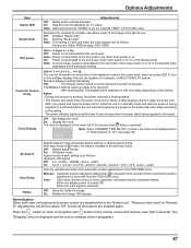
Options Adjustment Audio input select Set up the sound when an image input is displayed as below. Press to select audio input. Press to select image input. Image input Audio input [SLOT INPUT A] [SLOT INPUT B] [VIDEO] [COMPONENT] [HDMI] [DVI] [PC] SLOT INPUT A / VIDEO / COMPONENT / DVI / PC / NO AUDIO SLOT INPUT B / VIDEO / COMPONENT / DVI / PC / NO AUDIO SLOT INPUT A / SLOT INPUT B / VIDEO / COMPONENT / DVI / PC / NO AUDIO SLOT INPUT A / SLOT INPUT B / VIDEO / COMPONENT / DVI / PC / NO AUDIO SLOT INPUT A / SLOT INPUT B / VIDEO / COMPONENT / HDMI / DVI / PC / NO AUDIO SLOT INPUT ...
Options Adjustment Audio input select Set up the sound when an image input is displayed as below. Press to select audio input. Press to select image input. Image input Audio input [SLOT INPUT A] [SLOT INPUT B] [VIDEO] [COMPONENT] [HDMI] [DVI] [PC] SLOT INPUT A / VIDEO / COMPONENT / DVI / PC / NO AUDIO SLOT INPUT B / VIDEO / COMPONENT / DVI / PC / NO AUDIO SLOT INPUT A / SLOT INPUT B / VIDEO / COMPONENT / DVI / PC / NO AUDIO SLOT INPUT A / SLOT INPUT B / VIDEO / COMPONENT / DVI / PC / NO AUDIO SLOT INPUT A / SLOT INPUT B / VIDEO / COMPONENT / HDMI / DVI / PC / NO AUDIO SLOT INPUT ...
Operating Instructions
Page 62
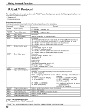
... information query 21: VIDEO input (VIDEO) 31: HDMI input (HDMI) 22: COMPONENT/RGB IN input (COMPONENT) 32: DVI-D IN input (DVI) Returns empty character (no name information) Returns "Panasonic" Returns "TH-50PF20" (for 50-inch model) Returns version number Returns "1" PJLink™ security authentication Set "Panasonic" for command INST? Command Control POWR Power control POWR? INF2? Error status query LAMP? INFO? Lamp status query INST? Input switch list query Remark Parameter 0 = Standby 1 = Power "On" Parameter 0 = Standby 1 = Power "On" Parameter...
... information query 21: VIDEO input (VIDEO) 31: HDMI input (HDMI) 22: COMPONENT/RGB IN input (COMPONENT) 32: DVI-D IN input (DVI) Returns empty character (no name information) Returns "Panasonic" Returns "TH-50PF20" (for 50-inch model) Returns version number Returns "1" PJLink™ security authentication Set "Panasonic" for command INST? Command Control POWR Power control POWR? INF2? Error status query LAMP? INFO? Lamp status query INST? Input switch list query Remark Parameter 0 = Standby 1 = Power "On" Parameter 0 = Standby 1 = Power "On" Parameter...
Operating Instructions
Page 66
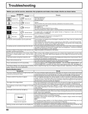
... type of time. The plasma display panel is manufactured using a video software program (such as such is nothing wrong with minimal movements are shown. Note: The permanent image retention on the Plasma Display resulting from inside the unit. The whirring sound is caused by any problems in the SET UP menu. Check whether the remote control designed specifically for use with the unit is being driven may change...
... type of time. The plasma display panel is manufactured using a video software program (such as such is nothing wrong with minimal movements are shown. Note: The permanent image retention on the Plasma Display resulting from inside the unit. The whirring sound is caused by any problems in the SET UP menu. Check whether the remote control designed specifically for use with the unit is being driven may change...

Operating Instructions
Page 71
... are approximate. 71 Specifications TH-42PF20U TH-50PF20U Power Source 110 - 127 V AC, 50/60 Hz Power Consumption Rated Power Consumption 400 W 475 W On mode Average Power Consumption∗ Stand-by condition Power off condition Plasma Display panel 165 W Save OFF 0.9 W, Save ON 0.4 W 0.2 W Drive method : AC type 42-inch, 16:9 aspect ratio 220 W Save OFF 0.9 W, Save ON 0.4 W 0.2 W Drive method : AC type 50-inch, 16:9 aspect ratio Screen size 36.2" (921 mm) (W) × 20...
... are approximate. 71 Specifications TH-42PF20U TH-50PF20U Power Source 110 - 127 V AC, 50/60 Hz Power Consumption Rated Power Consumption 400 W 475 W On mode Average Power Consumption∗ Stand-by condition Power off condition Plasma Display panel 165 W Save OFF 0.9 W, Save ON 0.4 W 0.2 W Drive method : AC type 42-inch, 16:9 aspect ratio 220 W Save OFF 0.9 W, Save ON 0.4 W 0.2 W Drive method : AC type 50-inch, 16:9 aspect ratio Screen size 36.2" (921 mm) (W) × 20...


