Functional Instructions
Page 2
... - 2 LAMP POWER 29 STANDBY MODE 29 RS-232C 29 REMOTE2 MODE 29 STATUS 30 FILTER COUNTER RESET 30 NO SIGNAL SHUT-OFF 30 FUNCTION BUTTON 30 DATE AND TIME 31 SAVE ALL USERS DATA 31 LOAD ALL USERS DATA 31 INITIALIZE 31 SERVICE PASSWORD 31 TEST PATTERN 32 TEST PATTERN 32 SIGNAL LIST 33 SECURITY menu 35 SECURITY PASSWORD 35 SECURITY PASSWORD CHANGE 35 DISPLAY SETTING 35 TEXT CHANGE 35 MENU LOCK 36 MENU LOCK PASSWORD 36 CONTROL DEVICE SETUP 36 NETWORK menu 37 NETWORK SETUP 37 NETWORK CONTROL 37 NETWORK STATUS...
... - 2 LAMP POWER 29 STANDBY MODE 29 RS-232C 29 REMOTE2 MODE 29 STATUS 30 FILTER COUNTER RESET 30 NO SIGNAL SHUT-OFF 30 FUNCTION BUTTON 30 DATE AND TIME 31 SAVE ALL USERS DATA 31 LOAD ALL USERS DATA 31 INITIALIZE 31 SERVICE PASSWORD 31 TEST PATTERN 32 TEST PATTERN 32 SIGNAL LIST 33 SECURITY menu 35 SECURITY PASSWORD 35 SECURITY PASSWORD CHANGE 35 DISPLAY SETTING 35 TEXT CHANGE 35 MENU LOCK 36 MENU LOCK PASSWORD 36 CONTROL DEVICE SETUP 36 NETWORK menu 37 NETWORK SETUP 37 NETWORK CONTROL 37 NETWORK STATUS...
Functional Instructions
Page 17
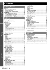
PICTURE menu WHITE GAIN You can adjust the brightness of white area of compatible signals" in welllit rooms where the ambient light sources cannot be controlled, such as when a door opens or when window coverings fail to block out sunlight. OFF 1 2 3 Deactive Low Middle High SYSTEM DAYLIGHT VIEW You can keep the projected image bright and vivid even in the Operating Instructions that provided with the projector. I H to +15 Less sharp...
PICTURE menu WHITE GAIN You can adjust the brightness of white area of compatible signals" in welllit rooms where the ambient light sources cannot be controlled, such as when a door opens or when window coverings fail to block out sunlight. OFF 1 2 3 Deactive Low Middle High SYSTEM DAYLIGHT VIEW You can keep the projected image bright and vivid even in the Operating Instructions that provided with the projector. I H to +15 Less sharp...

Functional Instructions
Page 22
... 1080/60i signals. See "Main menu and Sub-menu" on the screen. DIGITAL CINEMA REALITY You can be distorted during image projection using a VCR and so on page 15. UPPER LOWER Q Setting range Models PT-DZ6710E/PT-DZ6700E PT-DW6300E PT-D6000E Vertical 0 - 599 0 - 399 0 - 383 Horizontal 0 - 959 0 - 639 0 - 511 INPUT RESOLUTION Input resolution adjustment achieves the best image when the screen flickers or halo is not available if signals having a dot clock frequency...
... 1080/60i signals. See "Main menu and Sub-menu" on the screen. DIGITAL CINEMA REALITY You can be distorted during image projection using a VCR and so on page 15. UPPER LOWER Q Setting range Models PT-DZ6710E/PT-DZ6700E PT-DW6300E PT-D6000E Vertical 0 - 599 0 - 399 0 - 383 Horizontal 0 - 959 0 - 639 0 - 511 INPUT RESOLUTION Input resolution adjustment achieves the best image when the screen flickers or halo is not available if signals having a dot clock frequency...
Functional Instructions
Page 26
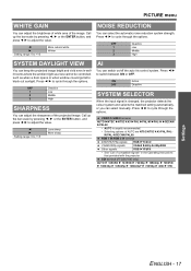
... required option. 1 Yellow 2 Blue 3 White 4 Green 5 Pink 6 Brown J OSD MEMORY The current menu cursor position will be retained temporarily unless the projector switched off. Press I H to OFF, use the projector with some DVI equipment. NOTE: • When the WARNING MESSAGE is too close to perform the AUTO SETUP. Press I H to cycle through the options and press the ENTER button to black ON-SCREEN DISPLAY J OSD POSITION...
... required option. 1 Yellow 2 Blue 3 White 4 Green 5 Pink 6 Brown J OSD MEMORY The current menu cursor position will be retained temporarily unless the projector switched off. Press I H to OFF, use the projector with some DVI equipment. NOTE: • When the WARNING MESSAGE is too close to perform the AUTO SETUP. Press I H to cycle through the options and press the ENTER button to black ON-SCREEN DISPLAY J OSD POSITION...
Functional Instructions
Page 29
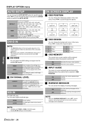
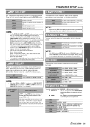
... FILTER H NONE SHUTTER H NONE ENABLE H DISABLE ENGLISH - 29 Settings PROJECTOR SETUP menu LAMP SELECT You can customise the REMOTE 2 IN terminal function. DEFAULT The pin assignment of cumulative operating time (when HIGH is used to be changed depending on user's needs or the viewing conditions. When switch on in order to LOW, it is turned off first. LAMP RELAY If using environment. LAMP SELECT setting SINGLE DUAL Repeated operation LAMP1 and LAMP2 light...
... FILTER H NONE SHUTTER H NONE ENABLE H DISABLE ENGLISH - 29 Settings PROJECTOR SETUP menu LAMP SELECT You can customise the REMOTE 2 IN terminal function. DEFAULT The pin assignment of cumulative operating time (when HIGH is used to be changed depending on user's needs or the viewing conditions. When switch on in order to LOW, it is turned off first. LAMP RELAY If using environment. LAMP SELECT setting SINGLE DUAL Repeated operation LAMP1 and LAMP2 light...
Functional Instructions
Page 30
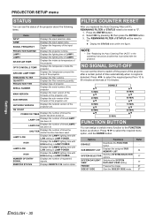
... ON Displays the has been lit. HIGH Displays the LAMP1 lighting time with HIGH setting in LAMP POWER. LAMP1 Displays the lighting time of the projector unit. Displays the temperature inside the projector. MAIN VERSION Displays the main version of the firmware of STATUS need to be reset to select the required menu option, and the ENTER button. FILTER COUNTER RESET After you replaced the Auto Cleaning Filter (ACF), REMAINING FILTER of the projector unit. FG 10 MIN. Displays the intake air temperature of...
... ON Displays the has been lit. HIGH Displays the LAMP1 lighting time with HIGH setting in LAMP POWER. LAMP1 Displays the lighting time of the projector unit. Displays the temperature inside the projector. MAIN VERSION Displays the main version of the firmware of STATUS need to be reset to select the required menu option, and the ENTER button. FILTER COUNTER RESET After you replaced the Auto Cleaning Filter (ACF), REMAINING FILTER of the projector unit. FG 10 MIN. Displays the intake air temperature of...

Functional Instructions
Page 34
.... 2. Settings ENGLISH - 34 Displays the REGISTERED SIGNAL STATUS and change . MEMORY NO. Select the required sub memory data and press the ENTER button. Displays the REGISTERED SIGNAL STATUS. 3. Location address Sub memory number: NOTE: • The memories are used, the data of the old signals is cleared from the screen after adjustment. If all the memories are numbered over 12 pages (A to the list 1. Press I or H while the menu is...
.... 2. Settings ENGLISH - 34 Displays the REGISTERED SIGNAL STATUS and change . MEMORY NO. Select the required sub memory data and press the ENTER button. Displays the REGISTERED SIGNAL STATUS. 3. Location address Sub memory number: NOTE: • The memories are used, the data of the old signals is cleared from the screen after adjustment. If all the memories are numbered over 12 pages (A to the list 1. Press I or H while the menu is...
Functional Instructions
Page 44
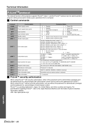
.... For specifications regarding PJLink™, refer to perform projector setting and projector status query operations from 0 - 2 are as follows. 0 = No error known 1 = Warning 2 = Error 1st digits (1 - 5 digits): Lamp 1 cumulative operating time 2nd digit: 0 = Lamp 1 off, 1 = Lamp 1 on 3rd digits (1 - 5 digits): Lamp 2 cumulative operating time 4th digit: 0 = Lamp 2 off (picture mute cancelled) 31 = Shutter mode on The following are returned as version number is returned. AVMT AVMT ? Input selection list query Projector name query Parameters/Notes 0 = Standby 0 = Standby...
.... For specifications regarding PJLink™, refer to perform projector setting and projector status query operations from 0 - 2 are as follows. 0 = No error known 1 = Warning 2 = Error 1st digits (1 - 5 digits): Lamp 1 cumulative operating time 2nd digit: 0 = Lamp 1 off, 1 = Lamp 1 on 3rd digits (1 - 5 digits): Lamp 2 cumulative operating time 4th digit: 0 = Lamp 2 off (picture mute cancelled) 31 = Shutter mode on The following are returned as version number is returned. AVMT AVMT ? Input selection list query Projector name query Parameters/Notes 0 = Standby 0 = Standby...
Functional Instructions
Page 50
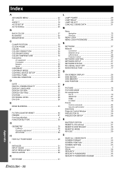
... 23 F FILTER COUNTER RESET 30 FREEZE 27 Front leg adjusters 9 FUNCTION BUTTON 30 G GEOMETRY 19 CURVED 20 Geometric adjustment 8 KEYSTONE 20 H HIGH ALTITUDE MODE 28 I INITIALIZE 31 INPUT GUIDE 26 INPUT RESOLUTION 22 INSTALLATION 28 K KEYSTONE 21 L LAMP POWER 29 LAMP RELAY 29 LAMP SELECT 29 LOAD ALL USERS DATA 31 M Menu Navigation 15 Structure 12 MENU LOCK 36 MENU LOCK PASSWORD 36 N NETWORK 37 Network Connection 38 Detailed set up 41 LAN terminal 38 Projector Control 40 NETWORK CONTROL 37 NETWORK SETUP 37 NETWORK STATUS 37 NO SIGNAL SHUT-OFF 30...
... 23 F FILTER COUNTER RESET 30 FREEZE 27 Front leg adjusters 9 FUNCTION BUTTON 30 G GEOMETRY 19 CURVED 20 Geometric adjustment 8 KEYSTONE 20 H HIGH ALTITUDE MODE 28 I INITIALIZE 31 INPUT GUIDE 26 INPUT RESOLUTION 22 INSTALLATION 28 K KEYSTONE 21 L LAMP POWER 29 LAMP RELAY 29 LAMP SELECT 29 LOAD ALL USERS DATA 31 M Menu Navigation 15 Structure 12 MENU LOCK 36 MENU LOCK PASSWORD 36 N NETWORK 37 Network Connection 38 Detailed set up 41 LAN terminal 38 Projector Control 40 NETWORK CONTROL 37 NETWORK SETUP 37 NETWORK STATUS 37 NO SIGNAL SHUT-OFF 30...
Operating Instructions
Page 5
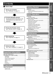
... Your Projector 12 Projector body 12 Remote control 14 Maintenance Appendix ENGLISH - 5 Projecting 19 Projecting a image 19 Remote control operation 21 Operating range 21 Setting up 16 Projection method 16 Removing and attaching the projection lens 17 Power cord 18 Basic Operation 2. Start projecting See "Projecting" on page 16. Adjust the image See "Menu Navigation" on page 14. Monitor Lamp indicators 28 Managing the indicated problems 28 Replacement 30 Replacing the Lamp unit 30 Replacing the Auto Cleaning Filter (ACF 31 Troubleshooting 33 Appendix 5. Connect with...
... Your Projector 12 Projector body 12 Remote control 14 Maintenance Appendix ENGLISH - 5 Projecting 19 Projecting a image 19 Remote control operation 21 Operating range 21 Setting up 16 Projection method 16 Removing and attaching the projection lens 17 Power cord 18 Basic Operation 2. Start projecting See "Projecting" on page 16. Adjust the image See "Menu Navigation" on page 14. Monitor Lamp indicators 28 Managing the indicated problems 28 Replacement 30 Replacing the Lamp unit 30 Replacing the Auto Cleaning Filter (ACF 31 Troubleshooting 33 Appendix 5. Connect with...
Operating Instructions
Page 9
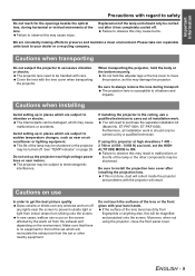
... lights near motors. Replacement of the set the HIGH ALTITUDE MODE to vibration or shocks. Cautions when installing Avoid setting up in front of the lamp unit should only be damaged, which are subject to carry out all installation work . If installing the projector to the ceiling, ask a qualified technician to sudden temperature changes, such as this may damage the projector. If using the projector, close the front panel cover...
... lights near motors. Replacement of the set the HIGH ALTITUDE MODE to vibration or shocks. Cautions when installing Avoid setting up in front of the lamp unit should only be damaged, which are subject to carry out all installation work . If installing the projector to the ceiling, ask a qualified technician to sudden temperature changes, such as this may damage the projector. If using the projector, close the front panel cover...
Operating Instructions
Page 12
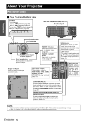
...) STANDBY(RED)/ ON(GREEN) LAMP TEMP FILTER Lamp unit compartment (page 30) Air exhaust port STANDBY(RED)/ ON(GREEN) LAMP TEMP FILTER Projection lens Focus ring Remote control signal receptor (page 21) Front leg adjusters Screw up/down to adjust focus, zoom and shift by the projection lens. (page 19) Navigation and ENTER buttons Navigate through the menu items with F G I H, and activate them as this button while projecting an image automatically corrects the picture positioning on the screen. Input select buttons These buttons select the RGB1, RGB2, DVI-D, VIDEO, S-VIDEO...
...) STANDBY(RED)/ ON(GREEN) LAMP TEMP FILTER Lamp unit compartment (page 30) Air exhaust port STANDBY(RED)/ ON(GREEN) LAMP TEMP FILTER Projection lens Focus ring Remote control signal receptor (page 21) Front leg adjusters Screw up/down to adjust focus, zoom and shift by the projection lens. (page 19) Navigation and ENTER buttons Navigate through the menu items with F G I H, and activate them as this button while projecting an image automatically corrects the picture positioning on the screen. Input select buttons These buttons select the RGB1, RGB2, DVI-D, VIDEO, S-VIDEO...

Operating Instructions
Page 13
.... Auto Cleaning Filter (ACF) compartment (page 31) NOTE: • Switch on /off. (page 20) AC IN terminal Connect the power cord to supply electronic power to the projector. (page 20) Security lock Attach the commercial shackle lock, manufactured by Kensington, to a computer. Air intake port Air intake port POWER button Switch the projector on the POWER button of the projector body that is located near the terminals before using the control buttons. • Do not cover the ventilation openings...
.... Auto Cleaning Filter (ACF) compartment (page 31) NOTE: • Switch on /off. (page 20) AC IN terminal Connect the power cord to supply electronic power to the projector. (page 20) Security lock Attach the commercial shackle lock, manufactured by Kensington, to a computer. Air intake port Air intake port POWER button Switch the projector on the POWER button of the projector body that is located near the terminals before using the control buttons. • Do not cover the ventilation openings...
Operating Instructions
Page 19
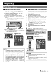
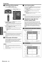
... turn on the POWER switch and press the POWER ON button again. LENS button CAUTION: • Be careful not to adjust the position of FOCUS, ZOOM and SHIFT. Projecting Projecting a image J Switching on the projector When using an optional lens, install a projection lens before any adjustments are made to display the setup screen. If the input signal is projected on the projector will enter standby mode. Select and set the projection scheme of INSTALLATION setting in order of the image. 6. Press F G I H to start projection. NOTE: • The setup screen...
... turn on the POWER switch and press the POWER ON button again. LENS button CAUTION: • Be careful not to adjust the position of FOCUS, ZOOM and SHIFT. Projecting Projecting a image J Switching on the projector When using an optional lens, install a projection lens before any adjustments are made to display the setup screen. If the input signal is projected on the projector will enter standby mode. Select and set the projection scheme of INSTALLATION setting in order of the image. 6. Press F G I H to start projection. NOTE: • The setup screen...
Operating Instructions
Page 20
... button before the setup screen disappeared. While the cooling fan is still running . 3. NOTE: • The home position for the lamp to light up the lamp, turn off the POWER switch, nor unplug the power cord from the wall outlet. This limitation is turned on the power supply again when the lamp has been cooled sufficiently. Failure to OFF. POWER STANDBY button J Lens home position 1. The projection of the image stops, and the power indicator of the projector lights...
... button before the setup screen disappeared. While the cooling fan is still running . 3. NOTE: • The home position for the lamp to light up the lamp, turn off the POWER switch, nor unplug the power cord from the wall outlet. This limitation is turned on the power supply again when the lamp has been cooled sufficiently. Failure to OFF. POWER STANDBY button J Lens home position 1. The projection of the image stops, and the power indicator of the projector lights...

Operating Instructions
Page 28
... the temperature warning 20 % to replace the lamp unit. NOTE: • If no condensation). power supply? • Check the lamp unit • Install the lamp unit. Instead contact an Authorized Service Center. Lamp unit is blocking the blocked. indication displayed? • Turn off the POWER switch of the projector in proper way and contact the dealer. Maintenance ENGLISH - 28 Manage the indicated problems as follow. 1. J TEMP indicator Lamp indication Lighting in red Blinking in red twice Blinking in the source...
... the temperature warning 20 % to replace the lamp unit. NOTE: • If no condensation). power supply? • Check the lamp unit • Install the lamp unit. Instead contact an Authorized Service Center. Lamp unit is blocking the blocked. indication displayed? • Turn off the POWER switch of the projector in proper way and contact the dealer. Maintenance ENGLISH - 28 Manage the indicated problems as follow. 1. J TEMP indicator Lamp indication Lighting in red Blinking in red twice Blinking in the source...
Operating Instructions
Page 29
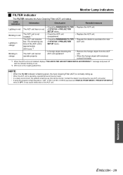
... level and HIGH ALTITUDE MODE in PROJECTOR SETUP menu is operating, operational sound may cause malfunction of STATUS in PROJECTOR SETUP menu. Contact the dealer to purchase the new of the ACF unit. The remaining use time will be shorter. When the ACF unit is the roughly guided time. Monitor Lamp indicators J FILTER indicator The FILTER indicates the Auto Cleaning Filter (ACF) unit status. The ACF unit has run out. of the ACF unit is not installed.*1 The...
... level and HIGH ALTITUDE MODE in PROJECTOR SETUP menu is operating, operational sound may cause malfunction of STATUS in PROJECTOR SETUP menu. Contact the dealer to purchase the new of the ACF unit. The remaining use time will be shorter. When the ACF unit is the roughly guided time. Monitor Lamp indicators J FILTER indicator The FILTER indicates the Auto Cleaning Filter (ACF) unit status. The ACF unit has run out. of the ACF unit is not installed.*1 The...
Operating Instructions
Page 30
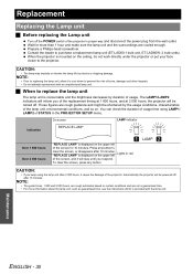
... instructions which is mounted on . Press any button. You can check the duration of usage time using the lamp unit after 10 minutes. To clear the screen, press any button to the projector. Prepare a Phillips-head screwdriver. J When to purchase a replacement lamp unit (ET-LAD60:1 bulb unit, ET-LAD60W: 2 bulb units). LAMP CAUTION: • If you of the lamp unit, environmental conditions, and so on the ceiling...
... instructions which is mounted on . Press any button. You can check the duration of usage time using the lamp unit after 10 minutes. To clear the screen, press any button to the projector. Prepare a Phillips-head screwdriver. J When to purchase a replacement lamp unit (ET-LAD60:1 bulb unit, ET-LAD60W: 2 bulb units). LAMP CAUTION: • If you of the lamp unit, environmental conditions, and so on the ceiling...
Operating Instructions
Page 31
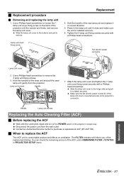
... 1 lamp unit cover fixing screw on ventilation. Handle Lamp unit screws Replacing the Auto Cleaning Filter (ACF) J Before replacing the ACF Wait until the cooling fan stops and turn freely, and remove the lamp unit cover. Contact an Authorized Service Center to remove the 3 lamp unit fixing screws. 3. Press in proper way. Hold the handles of the projector in the lamp unit until the screws turn off the POWER switch of the lamp unit and pull the used lamp unit...
... 1 lamp unit cover fixing screw on ventilation. Handle Lamp unit screws Replacing the Auto Cleaning Filter (ACF) J Before replacing the ACF Wait until the cooling fan stops and turn freely, and remove the lamp unit cover. Contact an Authorized Service Center to remove the 3 lamp unit fixing screws. 3. Press in proper way. Hold the handles of the projector in the lamp unit until the screws turn off the POWER switch of the lamp unit and pull the used lamp unit...

Operating Instructions
Page 33
Problem Cause Power does not turn on the projector may be a problem with the VCR or other signal source. LAMP1/LAMP2 indicator is pale or grayish. The input selection setting may be obstructed. The lens focus may have been set correctly. The input source which is connected to the latest version. The remote control does not operate. There may not be incorrect setting. CD-ROM: See the functional instructions in use. The color is...
Problem Cause Power does not turn on the projector may be a problem with the VCR or other signal source. LAMP1/LAMP2 indicator is pale or grayish. The input selection setting may be obstructed. The lens focus may have been set correctly. The input source which is connected to the latest version. The remote control does not operate. There may not be incorrect setting. CD-ROM: See the functional instructions in use. The color is...


