Operating Instructions
Page 1
AG-HPX500P Model No. S0407T1067 -P D Printed in Japan ENGLISH VQT1G18-1 AG-HPX500E FRANÇAIS Pour des explications en français, veuillez vous reporter au CD-ROM fourni. Before operating this product, please read the instructions carefully and save this manual for future use. Operating Instructions Memory Card Camera-Recorder Model No.
AG-HPX500P Model No. S0407T1067 -P D Printed in Japan ENGLISH VQT1G18-1 AG-HPX500E FRANÇAIS Pour des explications en français, veuillez vous reporter au CD-ROM fourni. Before operating this product, please read the instructions carefully and save this manual for future use. Operating Instructions Memory Card Camera-Recorder Model No.
Operating Instructions
Page 15
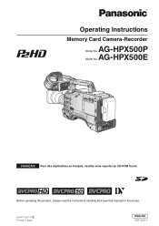
... 1 POWER switch Used to secure the light cable and microphone cable. 15 After the interior of your lens, see the relevant manufacturer's instruction manual. 13 Battery release lever Pull down the release lever to release the battery pack. 14 Viewfinder left-right positioning ring For details, ...mount When you want to [Mounting the Camera on a tripod, the optional tripod adapter (SHANTM700) is connected here. For details, refer to mount the AG-HPX500P/E on a Tripod] (page 100). 12 LENS jack (12-pin) The lens connection cord is attached here. For details, refer to [Mounting ...
... 1 POWER switch Used to secure the light cable and microphone cable. 15 After the interior of your lens, see the relevant manufacturer's instruction manual. 13 Battery release lever Pull down the release lever to release the battery pack. 14 Viewfinder left-right positioning ring For details, ...mount When you want to [Mounting the Camera on a tripod, the optional tripod adapter (SHANTM700) is connected here. For details, refer to mount the AG-HPX500P/E on a Tripod] (page 100). 12 LENS jack (12-pin) The lens connection cord is attached here. For details, refer to [Mounting ...
Operating Instructions
Page 16
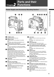
...designed to be depressed while turning. 3 AUDIO SELECT CH1/CH2 (audio channel 1 & 2 automatic/manual level adjustment selector) switch Use this switch to the MIC IN jack is recorded. MAN: Recording level manually controlled. 4 AUDIO LEVEL CH3/CH 4 (audio channel 3 & 4 recording level adjustment) controls Set... these jacks. CH3 FRONT REAR Input FRONT1 jack REAR1 jack CH4 FRONT REAR Input FRONT2 jack REAR2 jack With a front microphone (such as AG-MC200G) connected only to the FRONT2 jack, setting CH1 of audio channels 3 and 4. 5 AUDIO IN (audio input selector) switch Use this...
...designed to be depressed while turning. 3 AUDIO SELECT CH1/CH2 (audio channel 1 & 2 automatic/manual level adjustment selector) switch Use this switch to the MIC IN jack is recorded. MAN: Recording level manually controlled. 4 AUDIO LEVEL CH3/CH 4 (audio channel 3 & 4 recording level adjustment) controls Set... these jacks. CH3 FRONT REAR Input FRONT1 jack REAR1 jack CH4 FRONT REAR Input FRONT2 jack REAR2 jack With a front microphone (such as AG-MC200G) connected only to the FRONT2 jack, setting CH1 of audio channels 3 and 4. 5 AUDIO IN (audio input selector) switch Use this...
Operating Instructions
Page 56
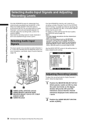
... to perform no sound output to make detailed audio settings. Note that the recording levels for Audio Channels 1 and 2 are automatically adjusted. To manually adjust the recording levels, position the switch at [AUTO], the recording levels for Audio Channels 3 and 4 are selected with the AUDIO IN switch...are 1 and 2. 2 Position the AUDIO SELECT CH1/CH2 switch at CH1/2 so that the channel indications displayed in the window are output as AG-MC200G) connected, setting CH1 of the AUDIO IN switch to FRONT2, setting CH2-CH4 to FRONT and setting the MONITOR SELECT CH1/2 / CH3/4...
... to perform no sound output to make detailed audio settings. Note that the recording levels for Audio Channels 1 and 2 are automatically adjusted. To manually adjust the recording levels, position the switch at [AUTO], the recording levels for Audio Channels 3 and 4 are selected with the AUDIO IN switch...are 1 and 2. 2 Position the AUDIO SELECT CH1/CH2 switch at CH1/2 so that the channel indications displayed in the window are output as AG-MC200G) connected, setting CH1 of the AUDIO IN switch to FRONT2, setting CH2-CH4 to FRONT and setting the MONITOR SELECT CH1/2 / CH3/4...

Operating Instructions
Page 131
...connected to the PC via USB. • The P2 card must be used as a mass storage device. 3 Press the MENU button to 5 meters. Select AG-HPX500 for AGHPX500P/E on the PC. • The camera is set the menu option PC MODE to USB DEVICE. Please use a commercially available USB 2.0 cable (... establish the USB connection for the first time, install the accessory P2 software for the USB driver during USB connection. Refer to the Installation Manual for establishing a connection with a PC 1 Connect the USB cable to the USB 2.0 port. • The USB 2.0 cable is in the PC mode. 5 Edit...
...connected to the PC via USB. • The P2 card must be used as a mass storage device. 3 Press the MENU button to 5 meters. Select AG-HPX500 for AGHPX500P/E on the PC. • The camera is set the menu option PC MODE to USB DEVICE. Please use a commercially available USB 2.0 cable (... establish the USB connection for the first time, install the accessory P2 software for the USB driver during USB connection. Refer to the Installation Manual for establishing a connection with a PC 1 Connect the USB cable to the USB 2.0 port. • The USB 2.0 cable is in the PC mode. 5 Edit...


