Service Manual
Page 8
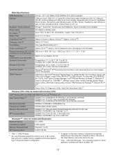
...on the actual system configuration. *3 A segment of the Video Memory cannot be set by TOSHIBA*14, Wireless Switch Utility, Hotkey Settings, Battery Recalibration Utility, LAN Power-Saving Utility, Infineon TPM Professional Package*26, Recover Pro™ 6*26 Setup Utility, PC-Diagnostic Utility, Hard.../157/161/165 IEEE802.11b/IEEE802.11g: Channels 1 to 11 RF Frequency Band IEEE802.11a: 5.18-5.32 GHz, 5.745-5.825 GHz IEEE802.11b/IEEE802.11g: 2.412-2.462 GHz Bluetooth™ Bluetooth Version 2.0 + EDR Transmission method FHSS system Wireless Channels Used Channels 1 to 79 RF ...
...on the actual system configuration. *3 A segment of the Video Memory cannot be set by TOSHIBA*14, Wireless Switch Utility, Hotkey Settings, Battery Recalibration Utility, LAN Power-Saving Utility, Infineon TPM Professional Package*26, Recover Pro™ 6*26 Setup Utility, PC-Diagnostic Utility, Hard.../157/161/165 IEEE802.11b/IEEE802.11g: Channels 1 to 11 RF Frequency Band IEEE802.11a: 5.18-5.32 GHz, 5.745-5.825 GHz IEEE802.11b/IEEE802.11g: 2.412-2.462 GHz Bluetooth™ Bluetooth Version 2.0 + EDR Transmission method FHSS system Wireless Channels Used Channels 1 to 79 RF ...
Service Manual
Page 9
... type or removable cartridge type can be used. *10 Only for model with touchscreen *11 A 16,777,216 color display is achieved by using Panasonic SD Memory Cards with the LAN Power-saving functions Auto-off setting set to 1 minute. *22 Measured using MobileMark™ 2005 (LCD brightness: ...60 cd/ m2) *24 Approx. 1.0 W when the battery pack is fully charged (or not being charged) and the computer is supplied with a 125 V AC compatible AC cord. 20-M-2-1 *20 Varies depending on the...
... type or removable cartridge type can be used. *10 Only for model with touchscreen *11 A 16,777,216 color display is achieved by using Panasonic SD Memory Cards with the LAN Power-saving functions Auto-off setting set to 1 minute. *22 Measured using MobileMark™ 2005 (LCD brightness: ...60 cd/ m2) *24 Approx. 1.0 W when the battery pack is fully charged (or not being charged) and the computer is supplied with a 125 V AC compatible AC cord. 20-M-2-1 *20 Varies depending on the...

Service Manual
Page 10
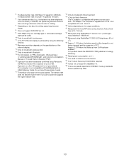
power on or resume due to low temperature.) P : Headphone jack : Battery status You can be ing green: Standby, Blinking green rapidly: Cannot recorded. Q :Wireless switch 2-1 Names and Functions of microphones are connected, audio from the internal ...
power on or resume due to low temperature.) P : Headphone jack : Battery status You can be ing green: Standby, Blinking green rapidly: Cannot recorded. Q :Wireless switch 2-1 Names and Functions of microphones are connected, audio from the internal ...
Service Manual
Page 11
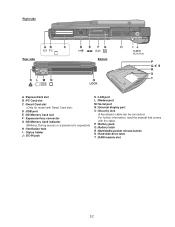
P : Battery pack Q :Battery latch R :Multimedia pocket release button S : Hard disk drive latch T : RAM module slot 2-2 For further information, read the manual that comes with the cable. Right side ...
P : Battery pack Q :Battery latch R :Multimedia pocket release button S : Hard disk drive latch T : RAM module slot 2-2 For further information, read the manual that comes with the cable. Right side ...

Service Manual
Page 12
... Speaker Sound AD1884 Beep ODD Bluetooth Touchscreen Wide Range Wireless BIOS SPI 8Mbit 25LF080 CRT Buffer CRT Serial Super I /O Board KB LED BKLT Li-Ion Battery Pack çTouch Pad Battery Charger Headphone Ext.
... Speaker Sound AD1884 Beep ODD Bluetooth Touchscreen Wide Range Wireless BIOS SPI 8Mbit 25LF080 CRT Buffer CRT Serial Super I /O Board KB LED BKLT Li-Ion Battery Pack çTouch Pad Battery Charger Headphone Ext.
Service Manual
Page 14
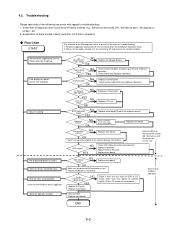
..., boards, etc. Set cannot be defective. Some or all be input. Starts but operates unstably. AC Adaptor/Battery Output voltage NG OK Power lamp NO check YES Inverter board NG OK Replace AC Adaptor/Battery Check contact condition of a troubleshooting. 1. Refer to display. HDD access NO YES Check HDD cable connection and...
..., boards, etc. Set cannot be defective. Some or all be input. Starts but operates unstably. AC Adaptor/Battery Output voltage NG OK Power lamp NO check YES Inverter board NG OK Replace AC Adaptor/Battery Check contact condition of a troubleshooting. 1. Refer to display. HDD access NO YES Check HDD cable connection and...
Service Manual
Page 16
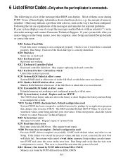
... enter Setup and enter your system displays one of except the messages marked below with an asterisk (*), write down the message and contact Panasonic Technical Support. Run Setup. May require replacing keyboard controller. 0213 Keyboard locked - May require board repair. *0280 Previous boot incomplete -... 6-1 Unlock key switch Unlock the system to see if fixed disk is correct. Replace the battery and run Setup. The BIOS installed Default SETUP Values. If the error persists, check the system battery or contact Panasonic Technical Support. 0260 System timer error The timer test failed.
... enter Setup and enter your system displays one of except the messages marked below with an asterisk (*), write down the message and contact Panasonic Technical Support. Run Setup. May require replacing keyboard controller. 0213 Keyboard locked - May require board repair. *0280 Previous boot incomplete -... 6-1 Unlock key switch Unlock the system to see if fixed disk is correct. Replace the battery and run Setup. The BIOS installed Default SETUP Values. If the error persists, check the system battery or contact Panasonic Technical Support. 0260 System timer error The timer test failed.

Service Manual
Page 22
...TS PCB I O PCB SERIAL CN1602 CN1203 CN1201 CN1202 CN1603 VGA CN1401 CN1402 LCD SPEAKER (R) CN1001 LED PCB SW1001 CN1003 POWER SW INVERTER BATTERY PACK CN17 CN18 CN802 CN801 CN15 CN21 CN23 SD PCB PORT REPLICATOR CN6 CN7 CN24 CN12 CN19 CN14 SPEAKER (L) CN1002 USB PCB CN1701 ...MODEM JACK USB CN16 ANTENNA PCB L CN28 MAIN PCB CN5 CN25 CN22 CN4 BLUETOOTH P.C.B. CN1 DIMM MEMORY CARD CN8 CN2 CN3 LITHIUM BATTERY WIRELESS MODULE ANTENNA PCB R JK2 JK1 Headphone Microphone KBD FPC KEYBOARD PCMCIA SLOT CN26 CN13 HDD PACK CN1301 SW1304 SW1301 Connector by Cable...
...TS PCB I O PCB SERIAL CN1602 CN1203 CN1201 CN1202 CN1603 VGA CN1401 CN1402 LCD SPEAKER (R) CN1001 LED PCB SW1001 CN1003 POWER SW INVERTER BATTERY PACK CN17 CN18 CN802 CN801 CN15 CN21 CN23 SD PCB PORT REPLICATOR CN6 CN7 CN24 CN12 CN19 CN14 SPEAKER (L) CN1002 USB PCB CN1701 ...MODEM JACK USB CN16 ANTENNA PCB L CN28 MAIN PCB CN5 CN25 CN22 CN4 BLUETOOTH P.C.B. CN1 DIMM MEMORY CARD CN8 CN2 CN3 LITHIUM BATTERY WIRELESS MODULE ANTENNA PCB R JK2 JK1 Headphone Microphone KBD FPC KEYBOARD PCMCIA SLOT CN26 CN13 HDD PACK CN1301 SW1304 SW1301 Connector by Cable...

Service Manual
Page 23
...8226; Please execute writing BIOS ID when you exchange the Main Board. • You cannot reuse the Conductive Clothes and the heat dissi- Removing the Battery Pack, the HDD Unit and the DVD-ROM Drive Unit 9.1.3. Disconnect the HDD from the HDD FPC. 4. Removing the HDD Hook HDD Case Upper... 1. Do not shut down Windows and turn off the computer. Push the MP Latch (6), and then without releasing it, slide and remove the Battery Pack. (3) HDD Unit 1. Remove the HDD Conductive Sheet and HDD Earth Plate. 9-1 Remove the six Hooks, and remove the HDD Case Upper. 2. Disassembly ...
...8226; Please execute writing BIOS ID when you exchange the Main Board. • You cannot reuse the Conductive Clothes and the heat dissi- Removing the Battery Pack, the HDD Unit and the DVD-ROM Drive Unit 9.1.3. Disconnect the HDD from the HDD FPC. 4. Removing the HDD Hook HDD Case Upper... 1. Do not shut down Windows and turn off the computer. Push the MP Latch (6), and then without releasing it, slide and remove the Battery Pack. (3) HDD Unit 1. Remove the HDD Conductive Sheet and HDD Earth Plate. 9-1 Remove the six Hooks, and remove the HDD Case Upper. 2. Disassembly ...

Service Manual
Page 26
...PCB 1. Disconnect the Cable from the Connector. 6. Remove the MP Guide. Screws : DFHE5025XA 9.1.11. Removing the PC Card Ejector and Lithium Battery Tape MDC Module (to CN14) PC Card Ejector Modem Cable 1. Disconnect the Modem Cable from the Connector (CN14). 4. Remove the two ...Screws . 2. Remove the Lithium Battery. Remove the six Screws . 3. Remove the Kapton tape and remove the MDC Module. 9.1.9. Removing the Wireless Module and MDC Module Kapton ...
...PCB 1. Disconnect the Cable from the Connector. 6. Remove the MP Guide. Screws : DFHE5025XA 9.1.11. Removing the PC Card Ejector and Lithium Battery Tape MDC Module (to CN14) PC Card Ejector Modem Cable 1. Disconnect the Modem Cable from the Connector (CN14). 4. Remove the two ...Screws . 2. Remove the Lithium Battery. Remove the six Screws . 3. Remove the Kapton tape and remove the MDC Module. 9.1.9. Removing the Wireless Module and MDC Module Kapton ...

Service Manual
Page 40
... the computer. 3. Tape Pass the Cable between the parts. (Avoid running over the parts.) Main PCB 9.2.11. Setting the PC Card Ejector and Lithium Battery 1. Match the end of the Tape. (0 to the Connector (CN14) on the back side. 3. Set the Main PCB to the Main PCB. 2. Fix the ...PC Card Ejector to CN14) (CN14) on the back side. Pass the Lead Wire of the Lithium Battery through the groove of the Main PCB, and connect it to the Connector Lithium Battery (to the Main PCB using the two Screws. Screws : DFHE5025XA CN14 PC Card Ejector Arranging the Lithium...
... the computer. 3. Tape Pass the Cable between the parts. (Avoid running over the parts.) Main PCB 9.2.11. Setting the PC Card Ejector and Lithium Battery 1. Match the end of the Tape. (0 to the Connector (CN14) on the back side. 3. Set the Main PCB to the Main PCB. 2. Fix the ...PC Card Ejector to CN14) (CN14) on the back side. Pass the Lead Wire of the Lithium Battery through the groove of the Main PCB, and connect it to the Connector Lithium Battery (to the Main PCB using the two Screws. Screws : DFHE5025XA CN14 PC Card Ejector Arranging the Lithium...

Service Manual
Page 47
Set the DVD-ROM Driver Unit. 2. Slide the Latch 1 to the locked position. Set the Battery Pack. 4. Setting the Battery Pack, the HDD Unit and the DVD-ROM Drive Unit 1. Set the HDD Pack. 3. Latch 1 HDD Unit DVD-ROM Drive Unit 1 Battery Pack 9-25 9.2.19.
Set the DVD-ROM Driver Unit. 2. Slide the Latch 1 to the locked position. Set the Battery Pack. 4. Setting the Battery Pack, the HDD Unit and the DVD-ROM Drive Unit 1. Set the HDD Pack. 3. Latch 1 HDD Unit DVD-ROM Drive Unit 1 Battery Pack 9-25 9.2.19.
Service Manual
Page 52
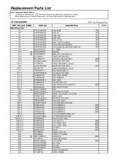
...PCB UNIT(SD) CF74 SUB PCB UNIT(PAD SWITCH) SO-DIMM MODEM WIRELESS LAN MODULE CABLE MODEM ASSY LITHIUM COIN BATTERY WLAN ANT PCB UNIT CABLE ANTENNA L (Black) WLAN ANT PCB UNIT CABLE ANTENNA L (Gray) HDD MOUNTINGK IT... PROTECTIVE FILM LCD SHEET A LCD SHEET HDN LCD SHEET SIDE TP SHEET SHEET CABLE LCD+TP CABLE TP POWER INVERTER CABLE INVERTER TOUCHPAD FFC. CF-74GCDADBM REF. Q'TY RTL 1 RTL 1 RTL 1 RTL 1 RTL 1 RTL 1 RTL 1 RTL 1 1 1 1 1 NRP 1 RTL 1 1 RTL 1 1 1 1 1 1 1 1 NRP 1 1 1 1 1 1 1 1 1 NRP 1 NRP 1 NRP 4 NRP 1 1 1 1 NRP 1...
...PCB UNIT(SD) CF74 SUB PCB UNIT(PAD SWITCH) SO-DIMM MODEM WIRELESS LAN MODULE CABLE MODEM ASSY LITHIUM COIN BATTERY WLAN ANT PCB UNIT CABLE ANTENNA L (Black) WLAN ANT PCB UNIT CABLE ANTENNA L (Gray) HDD MOUNTINGK IT... PROTECTIVE FILM LCD SHEET A LCD SHEET HDN LCD SHEET SIDE TP SHEET SHEET CABLE LCD+TP CABLE TP POWER INVERTER CABLE INVERTER TOUCHPAD FFC. CF-74GCDADBM REF. Q'TY RTL 1 RTL 1 RTL 1 RTL 1 RTL 1 RTL 1 RTL 1 RTL 1 1 1 1 1 NRP 1 RTL 1 1 RTL 1 1 1 1 1 1 1 1 NRP 1 1 1 1 1 1 1 1 1 NRP 1 NRP 1 NRP 4 NRP 1 1 1 1 NRP 1...
Service Manual
Page 53
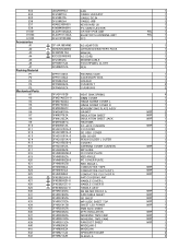
...K32 K33 K34 K35 K36 K37 K38 K39 K40 K41 K42 K43 UDQFRPH32 DFJS995YA DFJS987ZA DFJS992XA N2ABZJ000033 K1NB94BA0001 DL3UP1505AAA DL3UP1517AAA DFJK10T053DB S CF-AA1683AM3 S N4HUNTA00002 S DFQW5047ZA S K2CG3DR00003 DFJS954ZA DFHS9017ZA DFHR6207ZA DFPK1182YA DFPK1185ZA DFPE0827ZA DFPN0834ZA DFPN0835ZA DFUQ0110ZB DFMD7A65ZA-0 DFMD7A83ZA DFMD7A84ZA DFMD9098ZC DFMC0670YA... IN CABLE USB KEYBOARD US PC CARD EJECTOR CF74 BT PCB UNIT BLUETOOTH ANTENNA UNIT FFC AC ADAPTOR LITHIUM ION BATTERY PACK MANUAL AC CORD MODEM CABLE TOUCHPANEL CLOTH PEN PACKING CASE ACCESSORY BOX HOLDER CUSHION T CUSHION B HEAT SINK ...
...K32 K33 K34 K35 K36 K37 K38 K39 K40 K41 K42 K43 UDQFRPH32 DFJS995YA DFJS987ZA DFJS992XA N2ABZJ000033 K1NB94BA0001 DL3UP1505AAA DL3UP1517AAA DFJK10T053DB S CF-AA1683AM3 S N4HUNTA00002 S DFQW5047ZA S K2CG3DR00003 DFJS954ZA DFHS9017ZA DFHR6207ZA DFPK1182YA DFPK1185ZA DFPE0827ZA DFPN0834ZA DFPN0835ZA DFUQ0110ZB DFMD7A65ZA-0 DFMD7A83ZA DFMD7A84ZA DFMD9098ZC DFMC0670YA... IN CABLE USB KEYBOARD US PC CARD EJECTOR CF74 BT PCB UNIT BLUETOOTH ANTENNA UNIT FFC AC ADAPTOR LITHIUM ION BATTERY PACK MANUAL AC CORD MODEM CABLE TOUCHPANEL CLOTH PEN PACKING CASE ACCESSORY BOX HOLDER CUSHION T CUSHION B HEAT SINK ...

