Service Manual
Page 1
and Canada © 2006 Matsushita Electric Industrial Co., Ltd. ORDER NO. CPD0612203A1 Notebook Computer Model No. All rights reserved. CF-19CDBAXVM This is a violation of law. Unauthorized copying and distribution is the Service Manual for U.S.A. M ...for the following areas.
and Canada © 2006 Matsushita Electric Industrial Co., Ltd. ORDER NO. CPD0612203A1 Notebook Computer Model No. All rights reserved. CF-19CDBAXVM This is a violation of law. Unauthorized copying and distribution is the Service Manual for U.S.A. M ...for the following areas.
Service Manual
Page 6
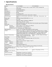
..., PC2-4200 Compliant Interface USB port (4-pin, USB 2.0) x 2, Serial Port (Dsub 9-pin male), Modem port (RJ-11), LAN port (RJ-45), External display port (Mini Dsub 15-pin female), Expansion Bus Connector (Dedicated 100-pin female), External Antenna Connector (Dedicated 50 coaxial connector) x 2, IEEE 1394a Interface Connector (4-pin x 1), Microphone Jack (Miniature jack, 3.5 DIA, Stereo), Headphone Jack (Miniature jack, 3.5 DIA, Impedance 32 , Output Power 4 mW × 2) Keyboard / Pointing Device 82 keys / Touch Pad / Touchscreen (Anti- 82 keys / Touch Pad / Digitizer (Anti-Re...
..., PC2-4200 Compliant Interface USB port (4-pin, USB 2.0) x 2, Serial Port (Dsub 9-pin male), Modem port (RJ-11), LAN port (RJ-45), External display port (Mini Dsub 15-pin female), Expansion Bus Connector (Dedicated 100-pin female), External Antenna Connector (Dedicated 50 coaxial connector) x 2, IEEE 1394a Interface Connector (4-pin x 1), Microphone Jack (Miniature jack, 3.5 DIA, Stereo), Headphone Jack (Miniature jack, 3.5 DIA, Impedance 32 , Output Power 4 mW × 2) Keyboard / Pointing Device 82 keys / Touch Pad / Touchscreen (Anti- 82 keys / Touch Pad / Digitizer (Anti-Re...
Service Manual
Page 7
... been enabled. *18 Rated power consumption 23-E-1 *19 Only for model with Bluetooth *9 For information on TPM, click [start] - [Run] and input "c:\util\drivers\tpm\README.pdf", and refer to the Installation Manual of "Trusted Platform Module (TPM)". *10 When using ExpressCard/34, the card slot cover cannot be set by TOSHIBA*8 , Wireless Switch Utility, Hotkey Settings, Battery Recalibration Utility, Panasonic Hand Writing*19, Software Keyboard*19, Display Rotation Tool, InÞneon TPM Professional Package*20, Recover ProTM 6*20 , Tablet Buttons Settings*19 Setup Utility, Hard Disk Data...
... been enabled. *18 Rated power consumption 23-E-1 *19 Only for model with Bluetooth *9 For information on TPM, click [start] - [Run] and input "c:\util\drivers\tpm\README.pdf", and refer to the Installation Manual of "Trusted Platform Module (TPM)". *10 When using ExpressCard/34, the card slot cover cannot be set by TOSHIBA*8 , Wireless Switch Utility, Hotkey Settings, Battery Recalibration Utility, Panasonic Hand Writing*19, Software Keyboard*19, Display Rotation Tool, InÞneon TPM Professional Package*20, Recover ProTM 6*20 , Tablet Buttons Settings*19 Setup Utility, Hard Disk Data...
Service Manual
Page 8
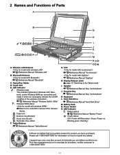
...ScrLk) : Hard disk drive status F: Tablet Buttons Reference Manual "Tablet Buttons" G: LCD Reference Manual "Touchscreen" Reference Manual "Digitizer" H: Display Release Latch page 12 "Switching to the Tablet mode" I: Speaker Reference Manual "Key Combinations" J: Function Key Reference Manual "Key Combinations" K: Keyboard L: Hard Disk Drive Reference Manual "Hard Disk Drive" M: Battery Pack N: Power Switch O: LED Indicator : Battery status Reference Manual "Battery Power" : Power status (Off: Power off/Hibernation, Green: Power on how to the instruction manual of Parts A: Wireless LAN...
...ScrLk) : Hard disk drive status F: Tablet Buttons Reference Manual "Tablet Buttons" G: LCD Reference Manual "Touchscreen" Reference Manual "Digitizer" H: Display Release Latch page 12 "Switching to the Tablet mode" I: Speaker Reference Manual "Key Combinations" J: Function Key Reference Manual "Key Combinations" K: Keyboard L: Hard Disk Drive Reference Manual "Hard Disk Drive" M: Battery Pack N: Power Switch O: LED Indicator : Battery status Reference Manual "Battery Power" : Power status (Off: Power off/Hibernation, Green: Power on how to the instruction manual of Parts A: Wireless LAN...
Service Manual
Page 9
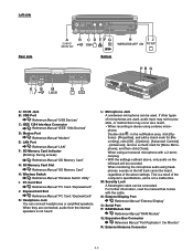
... and add a check mark for [Recording], click [OK] - [Options] - [Advanced Controls] - [Advanced], remove a check mark for [Mono Microphone], and then click [Close]. Left side Rear side Bottom A: DC-IN Jack B: USB Port Reference Manual "USB Devices" C: IEEE 1394 Interface Connector Reference Manual "IEEE 1394 Devices" D: Modem Port Reference Manual "Modem" E: LAN Port Reference Manual "LAN" F: SD Memory Card Indicator (Blinking: During access) Reference Manual "SD Memory Card" G: SD Memory Card Slot Reference Manual "SD Memory Card" H: Wireless Switch Reference Manual "Wireless Switch Utility...
... and add a check mark for [Recording], click [OK] - [Options] - [Advanced Controls] - [Advanced], remove a check mark for [Mono Microphone], and then click [Close]. Left side Rear side Bottom A: DC-IN Jack B: USB Port Reference Manual "USB Devices" C: IEEE 1394 Interface Connector Reference Manual "IEEE 1394 Devices" D: Modem Port Reference Manual "Modem" E: LAN Port Reference Manual "LAN" F: SD Memory Card Indicator (Blinking: During access) Reference Manual "SD Memory Card" G: SD Memory Card Slot Reference Manual "SD Memory Card" H: Wireless Switch Reference Manual "Wireless Switch Utility...
Service Manual
Page 12
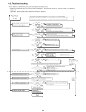
... be input. Replace if defective. OK Return set should all keys cannot be removed before operation check. 2. Replace HDD & Reinstall. 4.2. Replace if defective LCD back light lighting NO YES LCD unit NG check OK BIOS operation NO check YES Result of delivery from factory . Peripheral apparatus connected with current. Replace if defective. Troubleshooting Please take note of K/B connector in starting NG Replace main board. Make sure that cables, boards, etc. Screen fails to POST error code table...
... be input. Replace if defective. OK Return set should all keys cannot be removed before operation check. 2. Replace HDD & Reinstall. 4.2. Replace if defective LCD back light lighting NO YES LCD unit NG check OK BIOS operation NO check YES Result of delivery from factory . Peripheral apparatus connected with current. Replace if defective. Troubleshooting Please take note of K/B connector in starting NG Replace main board. Make sure that cables, boards, etc. Screen fails to POST error code table...
Service Manual
Page 14
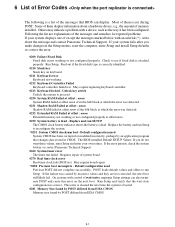
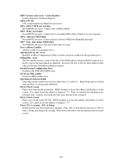
... run Setup. Run Setup and verify that changes data stored in not working or not configured properly at which the error was caused by POST differed from EISA CMOS Memory size found by POST differed from EISA CMOS. 6-1 May require board repair. *0280 Previous boot incomplete - May require replacing keyboard controller. 0213 Keyboard locked - Most of them display information about a hardware device, e.g., the amount of memory installed. This error is cleared the next time...
... run Setup. Run Setup and verify that changes data stored in not working or not configured properly at which the error was caused by POST differed from EISA CMOS Memory size found by POST differed from EISA CMOS. 6-1 May require board repair. *0280 Previous boot incomplete - May require replacing keyboard controller. 0213 Keyboard locked - Most of them display information about a hardware device, e.g., the amount of memory installed. This error is cleared the next time...
Service Manual
Page 15
... Utility to locate the address and display it on the screen. 02D0 System cache error - Press to resume, to enter a Setup and change the settings. Safe Timer NMI Failed ServerBIOS2 test error: Fail-Safe Timer takes too long. Press to start the boot process or to Setup Displayed after any recoverable error message. Cache disabled Contact Panasonic Technical Support. 02F0: CPU ID: CPU socket number for specified device. BIOS attempts to extended DMA (Direct Memory Access...
... Utility to locate the address and display it on the screen. 02D0 System cache error - Press to resume, to enter a Setup and change the settings. Safe Timer NMI Failed ServerBIOS2 test error: Fail-Safe Timer takes too long. Press to start the boot process or to Setup Displayed after any recoverable error message. Cache disabled Contact Panasonic Technical Support. 02F0: CPU ID: CPU socket number for specified device. BIOS attempts to extended DMA (Direct Memory Access...
Service Manual
Page 16
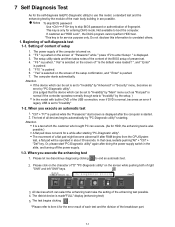
... an error if legacy USB is displayed after doing the power supply switch in about 30 seconds. Attention It is started. 2. Or, please start screen is set . 4. " F9 " is pushed, " Yes" is pushed. 7. Attention If the device which can be set is set to "Invalidity" by "Main" menu such as "Flat pad" is normal if the controller operates normally though sets to "Invalidity" by "PC-Diagnostic utility"'s starting "PC-Diagnostic utility". The...
... an error if legacy USB is displayed after doing the power supply switch in about 30 seconds. Attention It is started. 2. Or, please start screen is set . 4. " F9 " is pushed, " Yes" is pushed. 7. Attention If the device which can be set is set to "Invalidity" by "Main" menu such as "Flat pad" is normal if the controller operates normally though sets to "Invalidity" by "PC-Diagnostic utility"'s starting "PC-Diagnostic utility". The...
Service Manual
Page 18
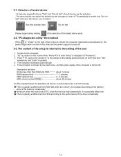
... chosen by the start menu, and the power supply of the screen is pushed. 4. Selection of tested device -To test only a specific device, "Test" and "Do not test" of each device can be selected. -The device which can select the enhancing test changes in order of the drive occasionally. 7-3 2-1. "PC-Diagnostic utility" End method When of "Close" on the screen while "Pressto enter Setup" is greatly...
... chosen by the start menu, and the power supply of the screen is pushed. 4. Selection of tested device -To test only a specific device, "Test" and "Do not test" of each device can be selected. -The device which can select the enhancing test changes in order of the drive occasionally. 7-3 2-1. "PC-Diagnostic utility" End method When of "Close" on the screen while "Pressto enter Setup" is greatly...
Service Manual
Page 19
... instruction", and DMA, INT, TIMER, and the RTC operation are confirmed. It is actually input, and Mainboard / in the AC97 modem controller. LAN PC Card SD Keyboard Touch Pad DVD-ROM It is confirmed not to find abnormality It is confirmed not to find abnormality The key is confirmed not to find abnormality in the CardBus controller. ating the touch pad. *6 The drive is normally reset, and...
... instruction", and DMA, INT, TIMER, and the RTC operation are confirmed. It is actually input, and Mainboard / in the AC97 modem controller. LAN PC Card SD Keyboard Touch Pad DVD-ROM It is confirmed not to find abnormality It is confirmed not to find abnormality The key is confirmed not to find abnormality in the CardBus controller. ating the touch pad. *6 The drive is normally reset, and...
Service Manual
Page 20
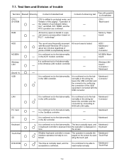
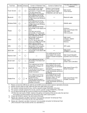
..., Graphic Controller)/ Memory GPS cable Main board (IEEE#394 Controller) Main board (Chipset)/ Express Card Connector Main board (Smart Card Controller) Main board (Super I/O)/ Serial Connector Main board (Super I/O)/ Parallel Connector *1 Please connect the USB device with the port (USB connector) which uses main memory as VRAM may fail with test result. The PC which wants to find abnormality in the wiring between Super I /O and Serial Connector. Test Item Touch Screen Bluetooth Wireless WAN Floppy Video GPS...
..., Graphic Controller)/ Memory GPS cable Main board (IEEE#394 Controller) Main board (Chipset)/ Express Card Connector Main board (Smart Card Controller) Main board (Super I/O)/ Serial Connector Main board (Super I/O)/ Parallel Connector *1 Please connect the USB device with the port (USB connector) which uses main memory as VRAM may fail with test result. The PC which wants to find abnormality in the wiring between Super I /O and Serial Connector. Test Item Touch Screen Bluetooth Wireless WAN Floppy Video GPS...
Service Manual
Page 22
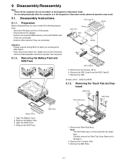
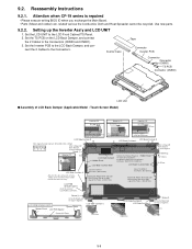
... 9.1.3. Open the HDD Cover. 4. Do not add peripherals while the computer is firmly fixed with two-sided tape. Preparation Before disassembling, be recycled. Use new parts. 9.1.2. Carefully remove the Palm Top Cover Sheet not to make the following preparations. • Shut down to the Suspend or hibernation mode. Remove the 4 Screws . 3. abnormal operation may result. 9.1. Do not shut down Windows and turn off the computer. Remove...
... 9.1.3. Open the HDD Cover. 4. Do not add peripherals while the computer is firmly fixed with two-sided tape. Preparation Before disassembling, be recycled. Use new parts. 9.1.2. Carefully remove the Palm Top Cover Sheet not to make the following preparations. • Shut down to the Suspend or hibernation mode. Remove the 4 Screws . 3. abnormal operation may result. 9.1. Do not shut down Windows and turn off the computer. Remove...
Service Manual
Page 27
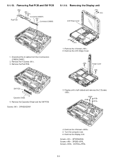
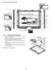
...+J7FNL 9-6 Removing the Display unit LCD Hinge Cover 1. Screws : DFHE5025XA 3. Turn the computer over. 6. Disconnect the 2 Cables from the 2 Connectors (CN805,CN807). 2. Remove the Pad PCB. 1. Remove the Operation Sheet and the SW PCB. Removing Pad PCB and SW PCB Pad PCB Connector(CN807) Connector(CN805) 9.1.14. Remove the 4 Screws . 5. Remove the 4 Screws . 3. Display unit is half-rotated and removes the 2 Screws . 4. Remove the Display Unit. Remove the 4 Screws . 2. 9.1.13. Hinge Cover SW PCB Operation Sheet 4.
...+J7FNL 9-6 Removing the Display unit LCD Hinge Cover 1. Screws : DFHE5025XA 3. Turn the computer over. 6. Disconnect the 2 Cables from the 2 Connectors (CN805,CN807). 2. Remove the Pad PCB. 1. Remove the Operation Sheet and the SW PCB. Removing Pad PCB and SW PCB Pad PCB Connector(CN807) Connector(CN805) 9.1.14. Remove the 4 Screws . 5. Remove the 4 Screws . 3. Display unit is half-rotated and removes the 2 Screws . 4. Remove the Display Unit. Remove the 4 Screws . 2. 9.1.13. Hinge Cover SW PCB Operation Sheet 4.
Service Manual
Page 28
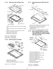
.... Remove the Pen Holder. Remove the 2 Screws . 6. Remove the 2 Screws . 3. Remove the 2 Screws . 2. Remove the 8 Screws on the back side of Display unit. 2. Remove the 10 Screws . 5. Removing Inverter PCB and LCD Unit Tape Inverter Case Connector Inverter PCB Connector Connector (CN901) TS PCB Connector (CN900) LCD Unit 1. Remove the LAN AUX Antenna PCB. 7. Remove 2 Antenna Covers and Tablet Latch Cover. 4. Remove the LCD Rear Case. Removing the LCD Hinge Cable Holder Plate Cable Holder Plate Cable...
.... Remove the Pen Holder. Remove the 2 Screws . 6. Remove the 2 Screws . 3. Remove the 2 Screws . 2. Remove the 8 Screws on the back side of Display unit. 2. Remove the 10 Screws . 5. Removing Inverter PCB and LCD Unit Tape Inverter Case Connector Inverter PCB Connector Connector (CN901) TS PCB Connector (CN900) LCD Unit 1. Remove the LAN AUX Antenna PCB. 7. Remove 2 Antenna Covers and Tablet Latch Cover. 4. Remove the LCD Rear Case. Removing the LCD Hinge Cable Holder Plate Cable Holder Plate Cable...
Service Manual
Page 30
... Tape Connector Inverter PCB Connector Connector (CN901) TS PCB Connector (CN900) LCD Unit n Assembly of LCD Back Damper (Applicable Model : Touch Screen Model) Detail of "B" 0 1mm Detail of "C" 0 1mm Detail of "D" 0 1mm 0 0.5mm Pass the Cable 0 0.5mm under the protrusion. Remove the Release Paper on the LCD Back Damper, and connect the 2 Cables to the Connectors (CN900 and CN901). 3. Lengthwise: Match to the LCD Front Cabinet/TS Panel. 2. LCD...
... Tape Connector Inverter PCB Connector Connector (CN901) TS PCB Connector (CN900) LCD Unit n Assembly of LCD Back Damper (Applicable Model : Touch Screen Model) Detail of "B" 0 1mm Detail of "C" 0 1mm Detail of "D" 0 1mm 0 0.5mm Pass the Cable 0 0.5mm under the protrusion. Remove the Release Paper on the LCD Back Damper, and connect the 2 Cables to the Connectors (CN900 and CN901). 3. Lengthwise: Match to the LCD Front Cabinet/TS Panel. 2. LCD...
Service Manual
Page 35
...rib, etc.. Screw Put the Cable on each hook 9.2.4. Set the Lock Plate and the Hinge Top Cover, and rotate the LCD Hinge to turn the Display Unit to the LCD Hinge. 2. C D Match to...Cable Cushion Tape Pen Holder Cable Cushion Put the center of Cabinet A Cable Cushion Attachment Method (3 Places) Bundle and wind 3 antenna cables. Fix the LCD Hinge using the 2 Screws and the 2 Cable Holder Plates. Details of "D" Insert it between the pins. Hook it. Fit another Cable Holder and clamp the Cable Holders in the Cable Holder. 4. Screw EVDO/EDGE Antenna Safety Working...
...rib, etc.. Screw Put the Cable on each hook 9.2.4. Set the Lock Plate and the Hinge Top Cover, and rotate the LCD Hinge to turn the Display Unit to the LCD Hinge. 2. C D Match to...Cable Cushion Tape Pen Holder Cable Cushion Put the center of Cabinet A Cable Cushion Attachment Method (3 Places) Bundle and wind 3 antenna cables. Fix the LCD Hinge using the 2 Screws and the 2 Cable Holder Plates. Details of "D" Insert it between the pins. Hook it. Fit another Cable Holder and clamp the Cable Holders in the Cable Holder. 4. Screw EVDO/EDGE Antenna Safety Working...
Service Manual
Page 57
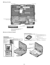
... Connect the LCD CABLE KBD FFC insert parts Screw Screw Screw Incline to make the LCD display face front after attaching. (Especially, put pressure around the sheets.) *Apply the load to attach. 30 to 40N (3.0 to 4.0Kgf) Cautions for Setting the Keyboard Safety Working Connect part the LCD CABLE/KBD FFC Connect the Connector to the dotted part. Exchange LCD cable - Screw Fix from the Hinge side. KBD Connector LID Ass'y Keyboard...
... Connect the LCD CABLE KBD FFC insert parts Screw Screw Screw Incline to make the LCD display face front after attaching. (Especially, put pressure around the sheets.) *Apply the load to attach. 30 to 40N (3.0 to 4.0Kgf) Cautions for Setting the Keyboard Safety Working Connect part the LCD CABLE/KBD FFC Connect the Connector to the dotted part. Exchange LCD cable - Screw Fix from the Hinge side. KBD Connector LID Ass'y Keyboard...
Service Manual
Page 69
... PC2-4200 SODIMM 512M INFINEON WLAN COAXIAL CABLE WIRELESS LAN MODULE THERMISTOR POWER SW CABLE TOUCHPAD LITHIUM COIN BATTERY LAN JACK CABLE EXPRESS PCMCIA COMBO SLOT LCD UNIT ASS'Y LCD ASS'Y LCD BACKLIGHT, CCFL REFLECTION ANGLE LCD BACK DAMPER LCD BACK CUSHION DG CCFL SCREW LCD BACK CUSHION DG SIDE LCD SIDE CUSHION A LCD SIDE CUSHION C LCD SIDE CUSHION D DIGITIZER SHEET LCD LIGHT SHIELD SHEET B ADHESIVE TAPE(PG SIDE...
... PC2-4200 SODIMM 512M INFINEON WLAN COAXIAL CABLE WIRELESS LAN MODULE THERMISTOR POWER SW CABLE TOUCHPAD LITHIUM COIN BATTERY LAN JACK CABLE EXPRESS PCMCIA COMBO SLOT LCD UNIT ASS'Y LCD ASS'Y LCD BACKLIGHT, CCFL REFLECTION ANGLE LCD BACK DAMPER LCD BACK CUSHION DG CCFL SCREW LCD BACK CUSHION DG SIDE LCD SIDE CUSHION A LCD SIDE CUSHION C LCD SIDE CUSHION D DIGITIZER SHEET LCD LIGHT SHIELD SHEET B ADHESIVE TAPE(PG SIDE...
Service Manual
Page 75
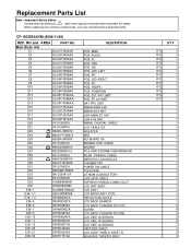
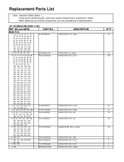
MAIN PCB C 1, 2, 3, 6, 7, 8, 10, 11, 12, 14, 15, 16, 18, 19, 20, 22, 23, 24, 27, 28, 29, 30, 31, 32, 33, 34, 35, 36, 37, 38, 39, 40, 43, 51, 52, 55, 59, 60, 62, ..., 50V, 18pF CAPACITOR, 10V, 0.1µF CAPACITOR, 50V, 6.0pF CAPACITOR, 6.3V, 150µF Q'TY 64 6 149 10 6 18 20 29 2 7 2 1 NO and AREA PART NO. CF-19CDBAXVM (2006/11/20) REF. Replacement Parts List Note: Important Safety Notice Components identified by ! mark have special characteristics important for safety. When replacing any of these components use only manufacturer's specified...
MAIN PCB C 1, 2, 3, 6, 7, 8, 10, 11, 12, 14, 15, 16, 18, 19, 20, 22, 23, 24, 27, 28, 29, 30, 31, 32, 33, 34, 35, 36, 37, 38, 39, 40, 43, 51, 52, 55, 59, 60, 62, ..., 50V, 18pF CAPACITOR, 10V, 0.1µF CAPACITOR, 50V, 6.0pF CAPACITOR, 6.3V, 150µF Q'TY 64 6 149 10 6 18 20 29 2 7 2 1 NO and AREA PART NO. CF-19CDBAXVM (2006/11/20) REF. Replacement Parts List Note: Important Safety Notice Components identified by ! mark have special characteristics important for safety. When replacing any of these components use only manufacturer's specified...


