Digital Video Record
Page 1
Ò NTSC Digital Video Camera Recorder Model AG- P Printed in Japan F0903T1093 @ VQT0F36-1 P Before operating this product, please read the instructions carefully and save this manual for future use.
Ò NTSC Digital Video Camera Recorder Model AG- P Printed in Japan F0903T1093 @ VQT0F36-1 P Before operating this product, please read the instructions carefully and save this manual for future use.
Digital Video Record
Page 5
...settings 37 Setting menus 39 Operation method 39 Configuration of setting menus 40 SCENE FILE screen 41 CAMERA SETUP screen 42 SW MODE screen 43 AUTO SW screen 44 PLAYBACK FUNCTIONS screen 44 RECORDING SETUP...AV IN/OUT SETUP screen 47 DISPLAY SETUP screen 48 OTHER FUNCTIONS screen 49 Screen displays 51 Camera mode and VCR mode 51 VCR mode 56 Selecting the display 57 Connecting external components 58 Shooting...registered trademark of the companies concerned. 5 are the trademarks and registered trademarks of Leica Camera AG. Other model names, company names, products names, etc.
...settings 37 Setting menus 39 Operation method 39 Configuration of setting menus 40 SCENE FILE screen 41 CAMERA SETUP screen 42 SW MODE screen 43 AUTO SW screen 44 PLAYBACK FUNCTIONS screen 44 RECORDING SETUP...AV IN/OUT SETUP screen 47 DISPLAY SETUP screen 48 OTHER FUNCTIONS screen 49 Screen displays 51 Camera mode and VCR mode 51 VCR mode 56 Selecting the display 57 Connecting external components 58 Shooting...registered trademark of the companies concerned. 5 are the trademarks and registered trademarks of Leica Camera AG. Other model names, company names, products names, etc.
Digital Video Record
Page 7
...to irreparable damage). Precautions for a prolonged period, its AC cable from the radio. O When the camera recorder is left inside the camera recorder when using the camera recorder on the camera recorder or give rise to the outlet. OThe electromagnetic waves from the set , the radiation of any... a component that generates magnetic fields to heed this is in close contact with insecticide sprays or volatile liquids, the camera body may damage the camera recorder and/or cassette. (Take particular care when inserting and ejecting the cassette.) AC adapter and battery OWhen the ...
...to irreparable damage). Precautions for a prolonged period, its AC cable from the radio. O When the camera recorder is left inside the camera recorder when using the camera recorder on the camera recorder or give rise to the outlet. OThe electromagnetic waves from the set , the radiation of any... a component that generates magnetic fields to heed this is in close contact with insecticide sprays or volatile liquids, the camera body may damage the camera recorder and/or cassette. (Take particular care when inserting and ejecting the cassette.) AC adapter and battery OWhen the ...
Digital Video Record
Page 8
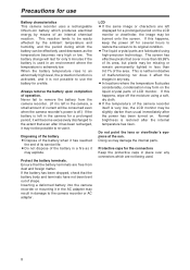
...its service life. LCD OIf the same image or characters are fabricated using a soft, dry cloth. Precautions for use Battery characteristics This camera recorder uses a rechargeable lithium-ion battery which produces electrical energy by the ambient temperature and humidity, and the period during which are ...liquid crystal parts are left in an environment where the temperature is very low, the LCD monitor may not be possible to the camera recorder or AC adapter. If this happens, keep the power off the moisture using high-precision technology. Doing so may explode. ...
...its service life. LCD OIf the same image or characters are fabricated using a soft, dry cloth. Precautions for use Battery characteristics This camera recorder uses a rechargeable lithium-ion battery which produces electrical energy by the ambient temperature and humidity, and the period during which are ...liquid crystal parts are left in an environment where the temperature is very low, the LCD monitor may not be possible to the camera recorder or AC adapter. If this happens, keep the power off the moisture using high-precision technology. Doing so may explode. ...
Digital Video Record
Page 9
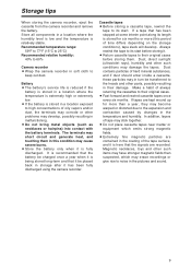
...in storage after it is fully discharged. Dust contains particles of the tape surface, and it has been fully discharged using the camera recorder. ODo not place cassette tapes near matter or equipment which may cause severe burns. OStore the battery only when it .... develop, possibly resulting in the temperature and humidity. Cassette tapes OBefore storing a cassette tape, rewind the tape to 60% Camera recorder OWrap the camera recorder in their original cases. OFast forward and rewind cassette tapes once every six months. It is recommended that the signals ...
...in storage after it is fully discharged. Dust contains particles of the tape surface, and it has been fully discharged using the camera recorder. ODo not place cassette tapes near matter or equipment which may cause severe burns. OStore the battery only when it .... develop, possibly resulting in the temperature and humidity. Cassette tapes OBefore storing a cassette tape, rewind the tape to 60% Camera recorder OWrap the camera recorder in their original cases. OFast forward and rewind cassette tapes once every six months. It is recommended that the signals ...
Digital Video Record
Page 10
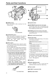
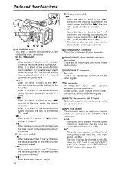
... 7Remote control sensor (rear) 8Tally lamp (rear) This lights or blinks depending on a flat and stable surface or, alternatively, support the camera recorder with the camera recorder placed on the status of the arrow while pressing the lock release button. Lights: While shooting is switched between the... there is little tape or battery charge remaining (once a second) The settings for causing the tally lamp to flash are performed using the CAMERA/VCR button >. 3EJECT switch To open but recording will continue, so external light and/or dust will be started or stopped. Operation is in...
... 7Remote control sensor (rear) 8Tally lamp (rear) This lights or blinks depending on a flat and stable surface or, alternatively, support the camera recorder with the camera recorder placed on the status of the arrow while pressing the lock release button. Lights: While shooting is switched between the... there is little tape or battery charge remaining (once a second) The settings for causing the tally lamp to flash are performed using the CAMERA/VCR button >. 3EJECT switch To open but recording will continue, so external light and/or dust will be started or stopped. Operation is in...
Digital Video Record
Page 11
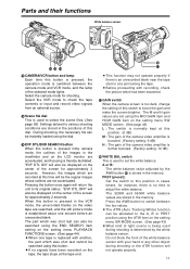
... outlines are recorded at this time will also be instantly loaded using the dial. @EVF DTL/END SEARCH button When this button is pressed inthe camera mode, the outlines of the images in cases where, for instance, there is replaced with another, the part which was shot last cannot be ... item setting on the setting menu SW MODE screen. (See page 43) L : The switch is normally kept at this position. (0 dB) M : The gain of the camera video amplifier is boosted. (Factory setting: 6 dB) H : The gain of the screen for shooting. OIf no time to the A, B or PRST position using the MID...
... outlines are recorded at this time will also be instantly loaded using the dial. @EVF DTL/END SEARCH button When this button is pressed inthe camera mode, the outlines of the images in cases where, for instance, there is replaced with another, the part which was shot last cannot be ... item setting on the setting menu SW MODE screen. (See page 43) L : The switch is normally kept at this position. (0 dB) M : The gain of the camera video amplifier is boosted. (Factory setting: 6 dB) H : The gain of the screen for shooting. OIf no time to the A, B or PRST position using the MID...
Digital Video Record
Page 14
... while the lever is tilted. US-VIDEO IN/OUT connector This is connected here. ZINPUT 1/2 switch This is used to change a setting. 14 [In the camera mode] "5" When the lever is tilted in the "5" direction in the shooting pause mode, the tape is played back in the "5" direction at 10a speed...
... while the lever is tilted. US-VIDEO IN/OUT connector This is connected here. ZINPUT 1/2 switch This is used to change a setting. 14 [In the camera mode] "5" When the lever is tilted in the "5" direction in the shooting pause mode, the tape is played back in the "5" direction at 10a speed...
Digital Video Record
Page 15
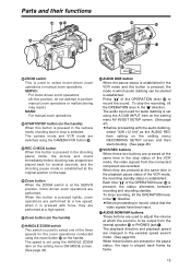
... status is played back frame by frame. 15 To stop the recording, tilt the OPERATION lever in the "$" direction. The camera mode and VCR mode are switched using the CAMERA/VCR button >. ]REC CHECK button When this button is pressed in the shooting pause mode, the picture and sound immediately before... page 43) [ ZOOM SERVO MANU aAUDIO DUB button When the pause status is established in the VCR mode and this button is pressed in the camera mode, shooting start shooting. (See page 45) bVCR REC buttons When these buttons are pressed in the pause status, the tape is established. The ...
... status is played back frame by frame. 15 To stop the recording, tilt the OPERATION lever in the "$" direction. The camera mode and VCR mode are switched using the CAMERA/VCR button >. ]REC CHECK button When this button is pressed in the shooting pause mode, the picture and sound immediately before... page 43) [ ZOOM SERVO MANU aAUDIO DUB button When the pause status is established in the VCR mode and this button is pressed in the camera mode, shooting start shooting. (See page 45) bVCR REC buttons When these buttons are pressed in the pause status, the tape is established. The ...
Digital Video Record
Page 16
... switched using the EVF MODE item on the setting menu DISPLAY SETUP screen. (See page 45) OPEN eLCD monitor fInternal speaker gRESET button If the camera recorder cannot be operated even though its power is used to select the input signals which are to be operated in the direction of the... to ON, +48 V power (power supply for the phantom mic) is supplied to the INPUT 2 connector. 16 Refrain from pressing the RESET button when the camera recorder is supplied to open the LCD monitor e. When the LCD monitor is used to select the input signals which are to be erased. INT...
... switched using the EVF MODE item on the setting menu DISPLAY SETUP screen. (See page 45) OPEN eLCD monitor fInternal speaker gRESET button If the camera recorder cannot be operated even though its power is used to select the input signals which are to be operated in the direction of the... to ON, +48 V power (power supply for the phantom mic) is supplied to the INPUT 2 connector. 16 Refrain from pressing the RESET button when the camera recorder is supplied to open the LCD monitor e. When the LCD monitor is used to select the input signals which are to be erased. INT...
Digital Video Record
Page 17
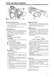
...it is pressed, the data to zero. TC : The time code is displayed. Blank display : No data is displayed. When shooting using the CAMERA/VCR button. 4 When the tape is now rewound or fast forwarded, it stops traveling automatically near where the counter value was reset. sTripod mounting ... displayed. COUNTER: The counter value is displayed. When the compensation is ON, appears in the viewfinder and on this button is pressed in camera mode, a zebra pattern or marker appears in the viewfinder and on the LCD monitor. The zebra pattern which is in the viewfinder and ...
...it is pressed, the data to zero. TC : The time code is displayed. Blank display : No data is displayed. When shooting using the CAMERA/VCR button. 4 When the tape is now rewound or fast forwarded, it stops traveling automatically near where the counter value was reset. sTripod mounting ... displayed. COUNTER: The counter value is displayed. When the compensation is ON, appears in the viewfinder and on this button is pressed in camera mode, a zebra pattern or marker appears in the viewfinder and on the LCD monitor. The zebra pattern which is in the viewfinder and ...
Digital Video Record
Page 18
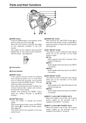
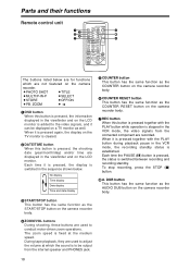
... date (year/month/day) and/or time are displayed in the VCR mode, the recording standby status is to be displayed on the camera recorder body. 4ZOOM/VOL buttons During shooting, these buttons are recorded. No display Time display Date display Time and date display 5COUNTER button This... Each time the PAUSE (;) button is pressed, the status is pressed together with the PLAY button during playback pause in the viewfinder and on the camera recorder. ZOOM MENU SET ITEM 3 8 4 The buttons listed below . When it can be output from the connected component are used to adjust ...
... date (year/month/day) and/or time are displayed in the VCR mode, the recording standby status is to be displayed on the camera recorder body. 4ZOOM/VOL buttons During shooting, these buttons are recorded. No display Time display Date display Time and date display 5COUNTER button This... Each time the PAUSE (;) button is pressed, the status is pressed together with the PLAY button during playback pause in the viewfinder and on the camera recorder. ZOOM MENU SET ITEM 3 8 4 The buttons listed below . When it can be output from the connected component are used to adjust ...

Digital Video Record
Page 19
... the reverse direction, D in the forward direction) INDEX buttons (:, 9) When either button is pressed in the menu mode, the items displayed on the camera recorder body. When the "V" or "B" button among the SET buttons ; "B" button: When this in the forward direction) PAUSE button (;) This button has...direction. ; ZOOM MENU SET ITEM : ; 9VCR operation buttons C/REW button (6) This button has the same function as the OPERATION lever on the camera recorder body. Parts and their functions 9 OSD START/ DATE/ PHOTO STOP TIME SHOT - Use the "V" button to change the speed in the...
... the reverse direction, D in the forward direction) INDEX buttons (:, 9) When either button is pressed in the menu mode, the items displayed on the camera recorder body. When the "V" or "B" button among the SET buttons ; "B" button: When this in the forward direction) PAUSE button (;) This button has...direction. ; ZOOM MENU SET ITEM : ; 9VCR operation buttons C/REW button (6) This button has the same function as the OPERATION lever on the camera recorder body. Parts and their functions 9 OSD START/ DATE/ PHOTO STOP TIME SHOT - Use the "V" button to change the speed in the...

Digital Video Record
Page 20
...order to prevent mistakes made in operations performed using the REMOTE item on the setting menu OTHER FUNCTIONS screen. (See page 49) If the camera recorder body and remote control unit settings are set to work for "VCR1" applications and for "VCR2" applications. OCamera recorder body Set ...VCR1 and VCR2 using remote control when two camera recorders are set to its original position. Remote control unit Installing the battery 1 While pushing the knob in the direction of small children. ...
...order to prevent mistakes made in operations performed using the REMOTE item on the setting menu OTHER FUNCTIONS screen. (See page 49) If the camera recorder body and remote control unit settings are set to work for "VCR1" applications and for "VCR2" applications. OCamera recorder body Set ...VCR1 and VCR2 using remote control when two camera recorders are set to its original position. Remote control unit Installing the battery 1 While pushing the knob in the direction of small children. ...

Digital Video Record
Page 21
... the LCD monitor is used near a radio, the radio sound may take longer at a distance of any malfunctioning. OIf the "CHARGE" lamp continues to the camera recorder. 21 OWhen the battery is 60%. OIf the DC cable is normal and not indicative of at least one meter from the AC adapter... automatically. CHARGE POWER 3 Upon completion of the charging, the "CHARGE" lamp on the AC adapter light up during operation and during charging, as does the camera recorder body. Charging may be heard while the AC adapter is in the above table apply when the ambient temperature is 68°F (20°...
... the LCD monitor is used near a radio, the radio sound may take longer at a distance of any malfunctioning. OIf the "CHARGE" lamp continues to the camera recorder. 21 OWhen the battery is 60%. OIf the DC cable is normal and not indicative of at least one meter from the AC adapter... automatically. CHARGE POWER 3 Upon completion of the charging, the "CHARGE" lamp on the AC adapter light up during operation and during charging, as does the camera recorder body. Charging may be heard while the AC adapter is in the above table apply when the ambient temperature is 68°F (20°...
Digital Video Record
Page 22
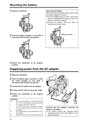
... position. CAUTION: O This unit will not drop. 2 Push the battery straight in the figure. Battery eject button 1 23 3 Return the viewfinder to ensure that the CAMERA/VCR lamp has gone off before removing the battery. OThe battery cannot be charged while supplying power from the AC 22 1 2 4 3 Connect the AC adapter... DC cable to the AC adapter. 4 Connect the AC cable to the power outlet. 5 Return the viewfinder to remove. OSet the POWER switch to the camera recorder. If a conversion plug is on 110/120/220/240V AC. Mounting the battery 1 Raise the viewfinder.
... position. CAUTION: O This unit will not drop. 2 Push the battery straight in the figure. Battery eject button 1 23 3 Return the viewfinder to ensure that the CAMERA/VCR lamp has gone off before removing the battery. OThe battery cannot be charged while supplying power from the AC 22 1 2 4 3 Connect the AC adapter... DC cable to the AC adapter. 4 Connect the AC cable to the power outlet. 5 Return the viewfinder to remove. OSet the POWER switch to the camera recorder. If a conversion plug is on 110/120/220/240V AC. Mounting the battery 1 Raise the viewfinder.

Digital Video Record
Page 23
... mosaic-type noise may occur and/or proper operation may apply to open the cassette holder. OIf the a cassette is not going to the camera recorder. 2 While pressing the lock release button, slide the EJECT switch in progress. To prevent accidental erasure of the functions. EJECT REC SAVE.... OOperations cannot be inserted immediately after one has been removed, keep the cassette holder closed. O When a tape which was shot by this camera recorder in the LP mode is played back in another digital video component O When a tape which was shot by another digital video component in...
... mosaic-type noise may occur and/or proper operation may apply to open the cassette holder. OIf the a cassette is not going to the camera recorder. 2 While pressing the lock release button, slide the EJECT switch in progress. To prevent accidental erasure of the functions. EJECT REC SAVE.... OOperations cannot be inserted immediately after one has been removed, keep the cassette holder closed. O When a tape which was shot by this camera recorder in the LP mode is played back in another digital video component O When a tape which was shot by another digital video component in...

Digital Video Record
Page 24
... and tightly. Fixing screw 24 OEnsure that its mark is recommended that the shoulder strap be attached to ensure that you do not drop the camera recorder. 20 mm or more 20 mm or more Mounting the lens hood Removing the lens hood OLoosen the fixing screw, and turn the lens...
... and tightly. Fixing screw 24 OEnsure that its mark is recommended that the shoulder strap be attached to ensure that you do not drop the camera recorder. 20 mm or more 20 mm or more Mounting the lens hood Removing the lens hood OLoosen the fixing screw, and turn the lens...

Digital Video Record
Page 25
... come into sharp focus. OKeep the LCD monitor closed. 2 Position the viewfinder where its screen images can be seen most comfortably. Viewfinders This camera recorder has two viewfinders: a viewfinder that an image appears in the viewfinder. OThe brightness and color tones may damage the internal parts. 7... or 4 direction to ON, and check that uses a small LCD, and a 3.5inch LCD monitor. Use the one that the characters on the camera recorder to adjust the screen's brightness. (If the remote control unit is used , press the "M" button among the SET buttons.) EVF SET EVF ...
... come into sharp focus. OKeep the LCD monitor closed. 2 Position the viewfinder where its screen images can be seen most comfortably. Viewfinders This camera recorder has two viewfinders: a viewfinder that an image appears in the viewfinder. OThe brightness and color tones may damage the internal parts. 7... or 4 direction to ON, and check that uses a small LCD, and a 3.5inch LCD monitor. Use the one that the characters on the camera recorder to adjust the screen's brightness. (If the remote control unit is used , press the "M" button among the SET buttons.) EVF SET EVF ...

Digital Video Record
Page 26
... item concerned has been selected so that it is the same with either setting. Eye cup holder Eye cup Using the LCD monitor 1 Set the camera recorder's POWER switch to release the menu mode.
... item concerned has been selected so that it is the same with either setting. Eye cup holder Eye cup Using the LCD monitor 1 Set the camera recorder's POWER switch to release the menu mode.


