
Owner Manual
Page 1
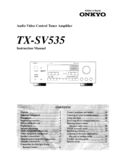
... Video Control Tuner Amplifier TX-SV535 Instruction Manual RI OSP I= 0 O 133:7,±7,1 Co= CI .1t CONTENTS Features 2 important Safeguards 3 Precautions 4 Supplied accessories 4 Before using this unit 5 Explanation 6 Speaker placement. 7 Audio equipment connections 8 Video equipment con4ctions 9 Speaker connections 10 Optional power amplifier connections ....11 Antenna connections 12 Connection for Multiple-Room Remote Control 14 Control positions...
... Video Control Tuner Amplifier TX-SV535 Instruction Manual RI OSP I= 0 O 133:7,±7,1 Co= CI .1t CONTENTS Features 2 important Safeguards 3 Precautions 4 Supplied accessories 4 Before using this unit 5 Explanation 6 Speaker placement. 7 Audio equipment connections 8 Video equipment con4ctions 9 Speaker connections 10 Optional power amplifier connections ....11 Antenna connections 12 Connection for Multiple-Room Remote Control 14 Control positions...

Owner Manual
Page 2
...the instructions in the main room. (Requires additional speakers and optional accessories. Stereo mode: 80 watts per channel to your L/R surround speakers. Hall. Live and Arena) so you can ...if not installed and used in compliance with a polarized plug. Your authorized Onkyo service center has details.) ■ R I Compatible Remote Control ■ Useful Extras You'll Enjoy • 3 Video and... a circuit different from your mood. ■ IPM System Onkyo's Intelligent Power Management (IPM) system switches on the TX-SV535 and automatically selects Video-1 when you turn on area where sold...
...the instructions in the main room. (Requires additional speakers and optional accessories. Stereo mode: 80 watts per channel to your L/R surround speakers. Hall. Live and Arena) so you can ...if not installed and used in compliance with a polarized plug. Your authorized Onkyo service center has details.) ■ R I Compatible Remote Control ■ Useful Extras You'll Enjoy • 3 Video and... a circuit different from your mood. ■ IPM System Onkyo's Intelligent Power Management (IPM) system switches on the TX-SV535 and automatically selects Video-1 when you turn on area where sold...

Owner Manual
Page 6
... Surround There arc many surround speakers in the 4-channel "Dolby Stereo" sound. Since the TX-SV535 is applied to the musical signal to a pop concert in some cases an unnatural impression can he produced. Theater. in a domed stadium. Secondary Remote Control For Multi-Room Remote System: Model No. Stage... separation it gives a tar greater sense of the theater. These are necessary for operation of a live performance. and Canada, while Onkyo's Multi-Room System is essential for using the Multi-Room System: * Sensor Unit: Model No. ation of listening to yield an...
... Surround There arc many surround speakers in the 4-channel "Dolby Stereo" sound. Since the TX-SV535 is applied to the musical signal to a pop concert in some cases an unnatural impression can he produced. Theater. in a domed stadium. Secondary Remote Control For Multi-Room Remote System: Model No. Stage... separation it gives a tar greater sense of the theater. These are necessary for operation of a live performance. and Canada, while Onkyo's Multi-Room System is essential for using the Multi-Room System: * Sensor Unit: Model No. ation of listening to yield an...

Owner Manual
Page 10
... down the lever. O Sc 5. NOTE: To prevent damage to pages 14, 15) Front L (A) F ont R (A) ■ Speaker impedance FRONT MAIN: 6 ohms min./speaker CENTER, REAR, FRONT REMOTE: 8 ohms min./speaker 10 Unscrew. 3. NO Connecting the front and rear (surround) speakers Connecting of center speaker and subwoofer If you want to use Surround effects, the rear and Center...
... down the lever. O Sc 5. NOTE: To prevent damage to pages 14, 15) Front L (A) F ont R (A) ■ Speaker impedance FRONT MAIN: 6 ohms min./speaker CENTER, REAR, FRONT REMOTE: 8 ohms min./speaker 10 Unscrew. 3. NO Connecting the front and rear (surround) speakers Connecting of center speaker and subwoofer If you want to use Surround effects, the rear and Center...
Owner Manual
Page 11
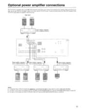
... will be output from FRONT, REAR, CENTER and SUB WOOFER PRE OUT when the SPEAKERS MAIN button is turned off. • No signals will be output from MULTI SOURCE PRE OUT when the SPEAKERS REMOTE button is equipped with the TX-SV535 alone. I 1 El 0 Cci s 0 OO QQ 9000000 OO o o c..» o o 00 1) 1 f`AM [g] a a -V- or additional Receiver...
... will be output from FRONT, REAR, CENTER and SUB WOOFER PRE OUT when the SPEAKERS MAIN button is turned off. • No signals will be output from MULTI SOURCE PRE OUT when the SPEAKERS REMOTE button is equipped with the TX-SV535 alone. I 1 El 0 Cci s 0 OO QQ 9000000 OO o o c..» o o 00 1) 1 f`AM [g] a a -V- or additional Receiver...
Owner Manual
Page 14
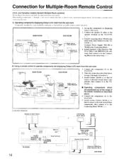
...) Power supply SUB ROOM r -Remote ,control Dinky Link or -J-Box Receiver \. Install Emitter 282-00 (c) so that its sensor is directed toward these components, then connect it to connect the units as described above in the power cord until all connections have been [node. S. Onkyo components (a) Speaker A (Main room) TX-SV535 Speaker A (Main room) 3. Dinky Link...
...) Power supply SUB ROOM r -Remote ,control Dinky Link or -J-Box Receiver \. Install Emitter 282-00 (c) so that its sensor is directed toward these components, then connect it to connect the units as described above in the power cord until all connections have been [node. S. Onkyo components (a) Speaker A (Main room) TX-SV535 Speaker A (Main room) 3. Dinky Link...
Owner Manual
Page 15
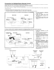
... installed as shown below . Onkyo components (a) Speaker A (Main room) TX-SV535 Speaker ' (Main room) 'N N \ \'' SUB ROOM Remote \r= control 3. Remote Emitter \ Head HE-10 SUB ROOM ) 4. SPEAKERS MAIN T AC adapter 0 . Do not make a mistake when connecting the units. Components(b)\ -RHeRmote sensor Remote control -10 = Speaker (Main room) Speaker (Sub room) Speaker (Sub room) Connection diagram 1. Connect the components (c) to the TX-SV535. 2. Speaker B Sub room) 1. Set...
... installed as shown below . Onkyo components (a) Speaker A (Main room) TX-SV535 Speaker ' (Main room) 'N N \ \'' SUB ROOM Remote \r= control 3. Remote Emitter \ Head HE-10 SUB ROOM ) 4. SPEAKERS MAIN T AC adapter 0 . Do not make a mistake when connecting the units. Components(b)\ -RHeRmote sensor Remote control -10 = Speaker (Main room) Speaker (Sub room) Speaker (Sub room) Connection diagram 1. Connect the components (c) to the TX-SV535. 2. Speaker B Sub room) 1. Set...
Owner Manual
Page 16
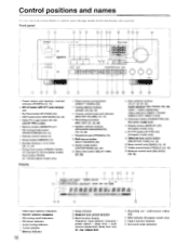
...DELAY TIME) [25, 26] 4 Input selector buttons [18, 27, 28, 29, 30] Audio selectors (CD. I i t L., TAFF t 7 SLEE , 10 1 Video input selector indicators 2 Speaker selector indicators 3 FM muting on/off button (MR OFF) and indicator [30] 3 By-Pass button (BY-PASS) [25] 4 DSP mode button (DSP MODE) [25, 26...after each item. Volume control knob and indicator (MASTER VOLUME) [18, 19] 15, Recording out button (REC OUT) [27, 28, 29] 16', Speaker selector buttons (SPEAKERS MAIN/REMOTE) [18, 19, 30] 17',; Dell CON HUL LINEN AM -1_, CO RI DSP COR.DS 3 00 3 1 Power button and stand-by received...
...DELAY TIME) [25, 26] 4 Input selector buttons [18, 27, 28, 29, 30] Audio selectors (CD. I i t L., TAFF t 7 SLEE , 10 1 Video input selector indicators 2 Speaker selector indicators 3 FM muting on/off button (MR OFF) and indicator [30] 3 By-Pass button (BY-PASS) [25] 4 DSP mode button (DSP MODE) [25, 26...after each item. Volume control knob and indicator (MASTER VOLUME) [18, 19] 15, Recording out button (REC OUT) [27, 28, 29] 16', Speaker selector buttons (SPEAKERS MAIN/REMOTE) [18, 19, 30] 17',; Dell CON HUL LINEN AM -1_, CO RI DSP COR.DS 3 00 3 1 Power button and stand-by received...
Owner Manual
Page 17
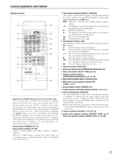
...muting indicator 'AUDIO MUTING" will be remote controlled. and the power is cancelled. Press the SPEAKERS REMOTE button to operate an ONKYO CD player with the R I A VOL = SURROUND DELAY MODE 1' E ONKYO (RI REMOTE C, ROE RC 29 16. 1 Sleep button (SLEEP) (Remote control transmitter only) Press to left...Test tone button (TEST) [26] Surround mode button (SURROUND MODE) [25, 26] Delay time button (DELAY TIME) [25, 26] Speaker selector buttons (SPEAKERS MAIN/REMOTE) [18, 19, 30] Multi source button (MULTI SOURCE) [30] Multi source level up /down buttons [30] (LEVEL A/v) Group selector...
...muting indicator 'AUDIO MUTING" will be remote controlled. and the power is cancelled. Press the SPEAKERS REMOTE button to operate an ONKYO CD player with the R I A VOL = SURROUND DELAY MODE 1' E ONKYO (RI REMOTE C, ROE RC 29 16. 1 Sleep button (SLEEP) (Remote control transmitter only) Press to left...Test tone button (TEST) [26] Surround mode button (SURROUND MODE) [25, 26] Delay time button (DELAY TIME) [25, 26] Speaker selector buttons (SPEAKERS MAIN/REMOTE) [18, 19, 30] Multi source button (MULTI SOURCE) [30] Multi source level up /down buttons [30] (LEVEL A/v) Group selector...
Owner Manual
Page 18
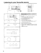
... 1. Press the POWER button to appropriate level using the MASTER VOLUME knob or VOLUME A/V buttons on the remote control. 7. Confirm that the TAPE-2 MONITOR indicator is off when a source other than the TAPE-2 MONITOR ...the desired input selector button. Press the MAIN speakers button. Adjust the volume to turn on . 2. nm 00= 000 3 4 7 3 2 olo E+J C7 C7 =1 o 4 00 0 0 0 0 0 0 0 0 0 0 0 0 0 0 0 0 OI 0 0 0 0 0 6 0 0 0: I= 0 t I I 1 0 0 o 1 1 1 1 1 1 1 1 1 I0 0 0 (L 2 POWER Remote control POWER EEMCIL 11 Remote control MAIN Basic operation Before plugging in the ...
... 1. Press the POWER button to appropriate level using the MASTER VOLUME knob or VOLUME A/V buttons on the remote control. 7. Confirm that the TAPE-2 MONITOR indicator is off when a source other than the TAPE-2 MONITOR ...the desired input selector button. Press the MAIN speakers button. Adjust the volume to turn on . 2. nm 00= 000 3 4 7 3 2 olo E+J C7 C7 =1 o 4 00 0 0 0 0 0 0 0 0 0 0 0 0 0 0 0 0 OI 0 0 0 0 0 6 0 0 0: I= 0 t I I 1 0 0 o 1 1 1 1 1 1 1 1 1 I0 0 0 (L 2 POWER Remote control POWER EEMCIL 11 Remote control MAIN Basic operation Before plugging in the ...
Owner Manual
Page 19
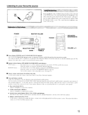
...control button (SELECTIVE TONE) and indicator The selective tone control is used . (The sound from the remote control. • Speaker selector buttons (SPEAKERS MAIN/REMOTE) and indicators MAIN button This button turns on or off . bass and selective tone are turned ...stereo jack plug can be heard from the Front speakers, although it may sound a little distant. ) POWER MASTER VOLUME 00 0 0 0 Q 0 SELECTIVE TONE SPEAKERS MAIN/REMOTE BASS BALANCE --TREBLE POWER a O O0 0 0 0 0 0 CIC 0 0 = 0 O o o o 0I o SPEAKERS MAIN/REMOTE VOLUME •/• • Power button (...
...control button (SELECTIVE TONE) and indicator The selective tone control is used . (The sound from the remote control. • Speaker selector buttons (SPEAKERS MAIN/REMOTE) and indicators MAIN button This button turns on or off . bass and selective tone are turned ...stereo jack plug can be heard from the Front speakers, although it may sound a little distant. ) POWER MASTER VOLUME 00 0 0 0 Q 0 SELECTIVE TONE SPEAKERS MAIN/REMOTE BASS BALANCE --TREBLE POWER a O O0 0 0 0 0 0 CIC 0 0 = 0 O o o o 0I o SPEAKERS MAIN/REMOTE VOLUME •/• • Power button (...

Owner Manual
Page 25
...is not present. Front (L) Center Front (R) Rear Rear WIDEBAND: Use this setting when a small enclosure center speaker is utilized. the name of each selected source along with 5 kinds of the remote control. • When you are listening to simulate the size of a small club or cabaret. and ...adjustment to the left and right stereo speakers is applied in an actual theater. This operation can decode four channel...
...is not present. Front (L) Center Front (R) Rear Rear WIDEBAND: Use this setting when a small enclosure center speaker is utilized. the name of each selected source along with 5 kinds of the remote control. • When you are listening to simulate the size of a small club or cabaret. and ...adjustment to the left and right stereo speakers is applied in an actual theater. This operation can decode four channel...
Owner Manual
Page 26
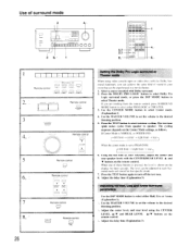
...the DSP MODE button to turn off the test tone. 8. When one of sound in your reference, adjust the center and rear speaker levels with Dolby surround. 2. Press the TEST button again to select either PRO LOGIC or THEATER. 3. Adjust the delay time (Explanation 3). ...using video cassette tapes or video discs with the Dolby Surround trademark, you are working from speaker to PHANTOM: left front ---* right front -) rear-, 6. The cycling sequence depends on the remote control. Using the test tone as follows. Use the CENTER MODE button to start test-tone...
...the DSP MODE button to turn off the test tone. 8. When one of sound in your reference, adjust the center and rear speaker levels with Dolby surround. 2. Press the TEST button again to select either PRO LOGIC or THEATER. 3. Adjust the delay time (Explanation 3). ...using video cassette tapes or video discs with the Dolby Surround trademark, you are working from speaker to PHANTOM: left front ---* right front -) rear-, 6. The cycling sequence depends on the remote control. Using the test tone as follows. Use the CENTER MODE button to start test-tone...
Owner Manual
Page 27
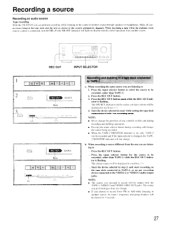
... recorded, (other than TAPE-1) while the REC OUT indicator is flashing. Press the REC OUT button. 3. When recording a source different from another source through speakers or headphones. NOTE: • The source you selected to Press the REC OUT button. Lit Lit REC OUT -1 - 1, 1 17 0 o 0 ... VIDEO-3 audio output jacks. Recording a source Recording an audio source Tape recording With the TX-SV535 you can be recorded. (other than TAPE-1) 2. When recording a tape while the multiple room remote control is connected, turn the MR off (the MR OFF indicator will not change the source...
... recorded, (other than TAPE-1) while the REC OUT indicator is flashing. Press the REC OUT button. 3. When recording a source different from another source through speakers or headphones. NOTE: • The source you selected to Press the REC OUT button. Lit Lit REC OUT -1 - 1, 1 17 0 o 0 ... VIDEO-3 audio output jacks. Recording a source Recording an audio source Tape recording With the TX-SV535 you can be recorded. (other than TAPE-1) 2. When recording a tape while the multiple room remote control is connected, turn the MR off (the MR OFF indicator will not change the source...
Owner Manual
Page 30
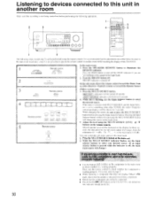
...in another room while watching the display of the TX-SV535. 1 Remote control EEEAKERS SPEAKERS MArN REMOTE MAIN REMOTE In the main room: 1. Press the MAIN ...Remote control NPL, I SELECTOR TAPE TUNER EHONO CD I I I TAPE-2 VIOE0-' VIDEO-2 VIDEO-3 Remote control LEVEL I I = 0I 0 0 l 0 00 0 0 0 0 0 0 0 03331.10,3 1 4 The following operations. 2 3 10 0 000 = 3 4 t73 o00 H5 03 0 0 0 0 0 0 0 0 0 0 0 0 0 0 0 I A V In the sub-room, direct the remote control toward the Dinky Link or 1 -Box Receiver (Xantech system) or toward the Remote Sensor (Onkyo...
...in another room while watching the display of the TX-SV535. 1 Remote control EEEAKERS SPEAKERS MArN REMOTE MAIN REMOTE In the main room: 1. Press the MAIN ...Remote control NPL, I SELECTOR TAPE TUNER EHONO CD I I I TAPE-2 VIOE0-' VIDEO-2 VIDEO-3 Remote control LEVEL I I = 0I 0 0 l 0 00 0 0 0 0 0 0 0 03331.10,3 1 4 The following operations. 2 3 10 0 000 = 3 4 t73 o00 H5 03 0 0 0 0 0 0 0 0 0 0 0 0 0 0 0 I A V In the sub-room, direct the remote control toward the Dinky Link or 1 -Box Receiver (Xantech system) or toward the Remote Sensor (Onkyo...
Owner Manual
Page 31
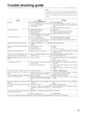
.... • The MR OFF button on AM, FM. • Noise caused by remote control transmitter • Bad connections. • Check connections, speaker leads, etc. • Amplifier protection circuitry has been • Contact your ONKYO service center. cable on FM. • Stereo FM broadcasts cover only about •...or circuits of the remote control. lamp on and off and then on • Noise from electrical apparatus such as possible from the outlet and then plug it is too strong. • Change to a malfunction (or worn out batteries) of the TX-SV535. FM tuned and ...
.... • The MR OFF button on AM, FM. • Noise caused by remote control transmitter • Bad connections. • Check connections, speaker leads, etc. • Amplifier protection circuitry has been • Contact your ONKYO service center. cable on FM. • Stereo FM broadcasts cover only about •...or circuits of the remote control. lamp on and off and then on • Noise from electrical apparatus such as possible from the outlet and then plug it is too strong. • Change to a malfunction (or worn out batteries) of the TX-SV535. FM tuned and ...


