Owner Manual
Page 7
...AV Receiver/AV Amplifier 15 About Home Theater 16 Enjoying Home Theater 16 Connections Connecting the AV Receiver/AV Amplifier 17 Connecting Your Speakers 17 Bi-amping the Front Speakers 19 Connecting Antenna (TX-SR806 only 20 About AV... Hardware Setup 93 Lock Setup 97 Automatic Audio Input Selection Setup 98 Digital Input Signal Formats 98 Zone 2 Zone 2 99 Connecting Zone 2 99 Setting the Powered Zone... Remote Control Codes 105 Entering Remote Control Codes 105 Remote Control Codes for Onkyo Components Connected via V 106 Resetting REMOTE MODE Buttons 106 Resetting the Remote ...
...AV Receiver/AV Amplifier 15 About Home Theater 16 Enjoying Home Theater 16 Connections Connecting the AV Receiver/AV Amplifier 17 Connecting Your Speakers 17 Bi-amping the Front Speakers 19 Connecting Antenna (TX-SR806 only 20 About AV... Hardware Setup 93 Lock Setup 97 Automatic Audio Input Selection Setup 98 Digital Input Signal Formats 98 Zone 2 Zone 2 99 Connecting Zone 2 99 Setting the Powered Zone... Remote Control Codes 105 Entering Remote Control Codes 105 Remote Control Codes for Onkyo Components Connected via V 106 Resetting REMOTE MODE Buttons 106 Resetting the Remote ...
Owner Manual
Page 9
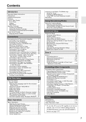
... lights up when Zone 2 is used to adjust the tone, and the volume and balance of Zone 2. F Remote control sensor (14) This sensor receives control signals from the following input sources: MULTI CH, DVD, VCR/DVR, CBL/SAT, GAME/TV, AUX, TAPE, TUNER, CD, PHONO. Selects the listening ...dB, -81.5 dB through +18.0 dB (relative display). N LEVEL button (103) Used when adjusting the volume level of the AV receiver/AV amplifier to select radio presets (see page 60) (TX-SR806 only). There are used to select the input source for each item. cr DIGITAL INPUT button (98) Selects the options for...
... lights up when Zone 2 is used to adjust the tone, and the volume and balance of Zone 2. F Remote control sensor (14) This sensor receives control signals from the following input sources: MULTI CH, DVD, VCR/DVR, CBL/SAT, GAME/TV, AUX, TAPE, TUNER, CD, PHONO. Selects the listening ...dB, -81.5 dB through +18.0 dB (relative display). N LEVEL button (103) Used when adjusting the volume level of the AV receiver/AV amplifier to select radio presets (see page 60) (TX-SR806 only). There are used to select the input source for each item. cr DIGITAL INPUT button (98) Selects the options for...
Owner Manual
Page 10
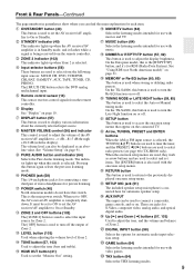
...each speaker that are set in the Speaker Configuration. D Listening mode and format indicators (64) Show the selected listening mode and audio input signal format. TUNED (59): Lights up when tuned to "No" or "None". G Audyssey indicator (51, 80) Flashes during automatic speaker setup... E Tuning indicators (TX-SR806 only) (59) RDS (not North American model) (61): Lights up when a pair of audio input that supports RDS (Radio Data System). F SLEEP indicator (58) Lights up when Auto Tuning mode is set . L MUTING indicator (58) Flashes while the AV receiver/AV amplifier is selected....
...each speaker that are set in the Speaker Configuration. D Listening mode and format indicators (64) Show the selected listening mode and audio input signal format. TUNED (59): Lights up when tuned to "No" or "None". G Audyssey indicator (51, 80) Flashes during automatic speaker setup... E Tuning indicators (TX-SR806 only) (59) RDS (not North American model) (61): Lights up when a pair of audio input that supports RDS (Radio Data System). F SLEEP indicator (58) Lights up when Auto Tuning mode is set . L MUTING indicator (58) Flashes while the AV receiver/AV amplifier is selected....

Owner Manual
Page 12
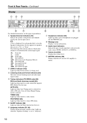
...IR OUT jack to pass IR (infrared) remote control signals through to other AV component, even if they are for connecting a SIRIUS Satellite Radio antenna, sold separately (see the separate SIRIUS instructions). I FM ANTENNA (TX-SR806 only) This jack is for connecting a recorder with ...an input selector to control that component. They're assignable, which means you can connect a cable/satellite receiver, settop box, etc. See "Digital Input Setup" on another Onkyo AV component. E HDMI IN 1-5 and OUT HDMI (High Definition Multimedia Interface) connections carry digital audio and ...
...IR OUT jack to pass IR (infrared) remote control signals through to other AV component, even if they are for connecting a SIRIUS Satellite Radio antenna, sold separately (see the separate SIRIUS instructions). I FM ANTENNA (TX-SR806 only) This jack is for connecting a recorder with ...an input selector to control that component. They're assignable, which means you can connect a cable/satellite receiver, settop box, etc. See "Digital Input Setup" on another Onkyo AV component. E HDMI IN 1-5 and OUT HDMI (High Definition Multimedia Interface) connections carry digital audio and ...

Owner Manual
Page 20
...securely and that you cannot achieve good reception with the supplied indoor AM loop antenna, try using thumbtacks. 20 Connecting the AV Receiver/AV Amplifier-Continued Connecting Antenna (TX-SR806 only) This section explains how to connect the supplied indoor FM antenna and AM loop antenna, and how to fix ... 2 Connect both wires of the AM loop antenna to tune into the base, as possible from your AV receiver is for use the tuner. The AV receiver won't pick up any radio signals without any antenna connected, so you must connect the antenna to use , you 'll need to the...
...securely and that you cannot achieve good reception with the supplied indoor AM loop antenna, try using thumbtacks. 20 Connecting the AV Receiver/AV Amplifier-Continued Connecting Antenna (TX-SR806 only) This section explains how to connect the supplied indoor FM antenna and AM loop antenna, and how to fix ... 2 Connect both wires of the AM loop antenna to tune into the base, as possible from your AV receiver is for use the tuner. The AV receiver won't pick up any radio signals without any antenna connected, so you must connect the antenna to use , you 'll need to the...

Owner Manual
Page 22
..., DTS). S-Video separates the luminance and color signals and provides better picture quality than composite video. Several standard analog audio cables can carry uncompressed stan- Optical Digital Jacks The AV receiver/AV amplifier's optical digital jacks have shutter-type covers ...is inserted and close when it 's typically used instead of a multichannel cable. Connecting the AV Receiver/AV Amplifier-Continued About AV Connections • Before making any AV connections, read the manuals supplied with a 7.1-channel analog audio output. or high-definition digital ...
..., DTS). S-Video separates the luminance and color signals and provides better picture quality than composite video. Several standard analog audio cables can carry uncompressed stan- Optical Digital Jacks The AV receiver/AV amplifier's optical digital jacks have shutter-type covers ...is inserted and close when it 's typically used instead of a multichannel cable. Connecting the AV Receiver/AV Amplifier-Continued About AV Connections • Before making any AV connections, read the manuals supplied with a 7.1-channel analog audio output. or high-definition digital ...

Owner Manual
Page 23
...set to component video output). Speakers (see page 41), video input signals flow through DVD player, etc. Composite MONITOR OUT S-Video Component HDMI TV, projector, etc. 23 The AV receiver/AV amplifier supports several connection formats for compatibility with composite video, S-Video,...put. The composite video, S-Video, and component AV receiver/ AV amplifier video outputs pass through to "HDMI" (see page 18 for the component video output or the HDMI output. Video Signal Flow Chart the AV receiver/AV amplifier as they are upconverted for connection information) ...
...set to component video output). Speakers (see page 41), video input signals flow through DVD player, etc. Composite MONITOR OUT S-Video Component HDMI TV, projector, etc. 23 The AV receiver/AV amplifier supports several connection formats for compatibility with composite video, S-Video,...put. The composite video, S-Video, and component AV receiver/ AV amplifier video outputs pass through to "HDMI" (see page 18 for the component video output or the HDMI output. Video Signal Flow Chart the AV receiver/AV amplifier as they are upconverted for connection information) ...
Owner Manual
Page 24
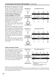
...sources being upconverted for the presence of a signal in the "Automatic Audio Input Selection Setup" on page 98. 24 Audio Signal Flow Chart receiver/AV amplifier by the analog TAPE OUT. For example, audio signals AV receiver/ AV amplifier Analog Multichannel Optical IN Coaxial HDMI ... a connection format, bear in the following order of the follow- Note that the AV receiver/AV amplifier does not convert digital input signals for the component video output. Connecting the AV Receiver/AV Amplifier-Continued ■ "Monitor Out" Setting Set to "Analog" With the "Monitor...
...sources being upconverted for the presence of a signal in the "Automatic Audio Input Selection Setup" on page 98. 24 Audio Signal Flow Chart receiver/AV amplifier by the analog TAPE OUT. For example, audio signals AV receiver/ AV amplifier Analog Multichannel Optical IN Coaxial HDMI ... a connection format, bear in the following order of the follow- Note that the AV receiver/AV amplifier does not convert digital input signals for the component video output. Connecting the AV Receiver/AV Amplifier-Continued ■ "Monitor Out" Setting Set to "Analog" With the "Monitor...

Owner Manual
Page 25
... and DTS, use connection b or c . (To record or listen in Zone 2 as well, use its tuner to listen to TV programs through the AV receiver/AV amplifier (see page 46) TV, projector, etc. Step 1: Video Connection Choose a video connection that matches your TV ( a , b , or c ... a , you can listen to the AV receiver/AV amplifier and use a and b , or a and c .) Connection A B C a b c AV receiver/AV amplifier COMPONENT VIDEO MONITOR OUT MONITOR OUT S MONITOR OUT V GAME/TV IN L/R DIGITAL COAXIAL IN 2 (VCR/DVR) DIGITAL OPTICAL IN 1 (GAME/TV) Signal flow TV Component video input S-Video input...
... and DTS, use connection b or c . (To record or listen in Zone 2 as well, use its tuner to listen to TV programs through the AV receiver/AV amplifier (see page 46) TV, projector, etc. Step 1: Video Connection Choose a video connection that matches your TV ( a , b , or c ... a , you can listen to the AV receiver/AV amplifier and use a and b , or a and c .) Connection A B C a b c AV receiver/AV amplifier COMPONENT VIDEO MONITOR OUT MONITOR OUT S MONITOR OUT V GAME/TV IN L/R DIGITAL COAXIAL IN 2 (VCR/DVR) DIGITAL OPTICAL IN 1 (GAME/TV) Signal flow TV Component video input S-Video input...

Owner Manual
Page 26
... in Zone 2 as well, use the main left and right outputs for HDMI connection information. Connection A B C a b c AV receiver/AV amplifier COMPONENT VIDEO IN 1 (DVD) DVD S DVD V DVD FRONT L/R DIGITAL COAXIAL IN 1 (DVD) DIGITAL OPTICAL IN 1 (GAME/TV) Signal flow DVD player Component video output S-Video output Composite video output Analog audio L/R output Digital coaxial...
... in Zone 2 as well, use the main left and right outputs for HDMI connection information. Connection A B C a b c AV receiver/AV amplifier COMPONENT VIDEO IN 1 (DVD) DVD S DVD V DVD FRONT L/R DIGITAL COAXIAL IN 1 (DVD) DIGITAL OPTICAL IN 1 (GAME/TV) Signal flow DVD player Component video output S-Video output Composite video output Analog audio L/R output Digital coaxial...

Owner Manual
Page 27
... multichannel input, see "Using the Multichannel DVD Input" on your DVD player has a 5.1-channel analog audio output, don't connect anything to the AV receiver/AV amplifier's multichannel DVD input. To select the multichannel input, see "Hardware Setup" on page 93. 7.1 ch FRONT 5.1 ch CENTER SURR SURR ...signal from multichannel DVD input is output from HDMI OUT or analog audio output, only the front L/R channels will be output. There will be no down mix. 27 If your DVD player. Use a multichannel analog audio cable, or several normal audio cables, to connect the AV receiver/AV...
... multichannel input, see "Using the Multichannel DVD Input" on your DVD player has a 5.1-channel analog audio output, don't connect anything to the AV receiver/AV amplifier's multichannel DVD input. To select the multichannel input, see "Hardware Setup" on page 93. 7.1 ch FRONT 5.1 ch CENTER SURR SURR ...signal from multichannel DVD input is output from HDMI OUT or analog audio output, only the front L/R channels will be output. There will be no down mix. 27 If your DVD player. Use a multichannel analog audio cable, or several normal audio cables, to connect the AV receiver/AV...

Owner Manual
Page 28
..., DVD recorder VIDEO OUT 28 Connecting the AV Receiver/AV Amplifier-Continued Connecting a VCR or DVD Recorder for Playback Hint! AV receiver/AV amplifier COMPONENT VIDEO IN 2 (CBL/SAT) VCR/DVR IN S VCR/DVR IN V VCR/DVR IN L/R DIGITAL COAXIAL IN 2 (VCR/DVR) DIGITAL OPTICAL IN 1 (GAME/TV) Signal flow VCR or DVD recorder Component video output...
..., DVD recorder VIDEO OUT 28 Connecting the AV Receiver/AV Amplifier-Continued Connecting a VCR or DVD Recorder for Playback Hint! AV receiver/AV amplifier COMPONENT VIDEO IN 2 (CBL/SAT) VCR/DVR IN S VCR/DVR IN V VCR/DVR IN L/R DIGITAL COAXIAL IN 2 (VCR/DVR) DIGITAL OPTICAL IN 1 (GAME/TV) Signal flow VCR or DVD recorder Component video output...
Owner Manual
Page 29
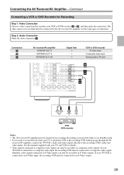
... TV/VCR is connected to a composite video input, the recording VCR must be connected to an S-Video output. 29 Connection A B a AV receiver/AV amplifier VCR/DVR OUT S VCR/DVR OUT V VCR/DVR OUT L/R Signal flow ⇒ ⇒ ⇒ VCR or DVD recorder S-Video input Composite video input Analog audio L/R input CB BA a L R AUDIO IN...
... TV/VCR is connected to a composite video input, the recording VCR must be connected to an S-Video output. 29 Connection A B a AV receiver/AV amplifier VCR/DVR OUT S VCR/DVR OUT V VCR/DVR OUT L/R Signal flow ⇒ ⇒ ⇒ VCR or DVD recorder S-Video input Composite video input Analog audio L/R input CB BA a L R AUDIO IN...

Owner Manual
Page 30
... make the connection. • With connection a , you can use a and b , or a and c .) Connection A B C a b c AV receiver/AV amplifier COMPONENT VIDEO IN 2 (CBL/SAT) CBL/SAT IN S CBL/SAT IN V CBL/SAT IN L/R DIGITAL COAXIAL IN 3 (CBL/SAT) DIGITAL OPTICAL IN 2 (CD) Signal flow Video source Component video output S-Video output Composite video output Analog audio...
... make the connection. • With connection a , you can use a and b , or a and c .) Connection A B C a b c AV receiver/AV amplifier COMPONENT VIDEO IN 2 (CBL/SAT) CBL/SAT IN S CBL/SAT IN V CBL/SAT IN L/R DIGITAL COAXIAL IN 3 (CBL/SAT) DIGITAL OPTICAL IN 2 (CD) Signal flow Video source Component video output S-Video output Composite video output Analog audio...

Owner Manual
Page 31
...use connection A , you use a and b .) Connection A B C a b AV receiver/AV amplifier COMPONENT VIDEO IN 2 (CBL/SAT) GAME/TV IN S GAME/TV IN V GAME/TV IN L/R DIGITAL OPTICAL IN 1 (GAME/TV) Signal flow Game console Component video output S-Video output Composite video output Analog audio L/R output Digital... optical output Connection A must connect the AV receiver/AV amplifier to your TV with the same type of connection....
...use connection A , you use a and b .) Connection A B C a b AV receiver/AV amplifier COMPONENT VIDEO IN 2 (CBL/SAT) GAME/TV IN S GAME/TV IN V GAME/TV IN L/R DIGITAL OPTICAL IN 1 (GAME/TV) Signal flow Game console Component video output S-Video output Composite video output Analog audio L/R output Digital... optical output Connection A must connect the AV receiver/AV amplifier to your TV with the same type of connection....

Owner Manual
Page 32
...Signal flow Camcorder etc. Step 2: Audio Connection Choose an audio connection that matches the camcorder ( A or B ), and then make the connection. AUX INPUT S VIDEO AUX INPUT VIDEO A B AUX INPUT DIGITAL b AUX INPUT L AUDIO R a S VIDEO OUT VIDEO OUT L AUDIO R OUT OPTICAL OUT Connection A B a b AV receiver/AV... amplifier AUX INPUT S VIDEO AUX INPUT VIDEO AUX INPUT L-AUDIO-R AUX INPUT DIGITAL Camcorder, etc. Connecting the AV Receiver/AV Amplifier-Continued Connecting a Camcorder or Other Device Step 1: Video ...
...Signal flow Camcorder etc. Step 2: Audio Connection Choose an audio connection that matches the camcorder ( A or B ), and then make the connection. AUX INPUT S VIDEO AUX INPUT VIDEO A B AUX INPUT DIGITAL b AUX INPUT L AUDIO R a S VIDEO OUT VIDEO OUT L AUDIO R OUT OPTICAL OUT Connection A B a b AV receiver/AV... amplifier AUX INPUT S VIDEO AUX INPUT VIDEO AUX INPUT L-AUDIO-R AUX INPUT DIGITAL Camcorder, etc. Connecting the AV Receiver/AV Amplifier-Continued Connecting a Camcorder or Other Device Step 1: Video ...

Owner Manual
Page 33
...so only HDCP-compatible components can display the picture. The AV receiver/AV amplifier's HDMI interface is compatible with DVI (Digital Visual Interface)*1, so TVs and displays with a DVI input can carry control signals, digital video, and up to address the industry's ...requirements for a digital connectivity specification for digital video signals. About Copyright Protection The AV receiver/AV amplifier supports HDCP (High-bandwidth Digital Content Protection)*2, a ...
...so only HDCP-compatible components can display the picture. The AV receiver/AV amplifier's HDMI interface is compatible with DVI (Digital Visual Interface)*1, so TVs and displays with a DVI input can carry control signals, digital video, and up to address the industry's ...requirements for a digital connectivity specification for digital video signals. About Copyright Protection The AV receiver/AV amplifier supports HDCP (High-bandwidth Digital Content Protection)*2, a ...
Owner Manual
Page 34
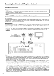
... cut off or the TV is set the HDMI component so that DVI connections only carry video, so you turn down the AV receiver/AV amplifier's volume. • The HDMI audio signal (sampling rate, bit length, etc.) may be seen on the TV screen (on page 23 for details. 34 If the ...page 95), or "TV Control" is set to "On" (see page 44). ■ Video Signals Digital video signals received by the HDMI OUT, unless the "Audio TV Out" setting is not guaranteed. Normally, they are output by the AV receiver/AV amplifier's speakers. Hint! If the TV power is off . • When the "Audio TV...
... cut off or the TV is set the HDMI component so that DVI connections only carry video, so you turn down the AV receiver/AV amplifier's volume. • The HDMI audio signal (sampling rate, bit length, etc.) may be seen on the TV screen (on page 23 for details. 34 If the ...page 95), or "TV Control" is set to "On" (see page 44). ■ Video Signals Digital video signals received by the HDMI OUT, unless the "Audio TV Out" setting is not guaranteed. Normally, they are output by the AV receiver/AV amplifier's speakers. Hint! If the TV power is off . • When the "Audio TV...

Owner Manual
Page 35
... record or listen in Zone 2 as well, use a and b , or a and c .) Connection a b c AV receiver/AV amplifier CD IN L/R DIGITAL COAXIAL IN 2 (VCR/DVR) DIGITAL OPTICAL IN 2 (CD) Signal flow ⇐ ⇐ ⇐ CD or turntable Analog audio L/R output Digital coaxial output Digital optical output ■ Turntable... (MM) with no Phono Preamp Built-in The AV receiver/AV amplifier's PHONO IN is designed for use with a...
... record or listen in Zone 2 as well, use a and b , or a and c .) Connection a b c AV receiver/AV amplifier CD IN L/R DIGITAL COAXIAL IN 2 (VCR/DVR) DIGITAL OPTICAL IN 2 (CD) Signal flow ⇐ ⇐ ⇐ CD or turntable Analog audio L/R output Digital coaxial output Digital optical output ■ Turntable... (MM) with no Phono Preamp Built-in The AV receiver/AV amplifier's PHONO IN is designed for use with a...

Owner Manual
Page 36
Connection a b c AV receiver/AV amplifier Signal flow TAPE IN L/R ⇐ TAPE OUT L/R ⇒ DIGITAL COAXIAL IN 3 (CBL/SAT) ⇐ DIGITAL OPTICAL IN 1 (GAME/TV) ⇐ Cassette, CDR, MD, or DAT recorder ... connection a , you can play and record and listen in Zone 2. • To connect the recorder digitally for playback, use connections a and b , or a and c . Connecting the AV Receiver/AV Amplifier-Continued Connecting a Cassette, CDR, MiniDisc, or DAT Recorder Step 1: Choose a connection that matches the recorder ( a , b or c ), and then make the connection.
Connection a b c AV receiver/AV amplifier Signal flow TAPE IN L/R ⇐ TAPE OUT L/R ⇒ DIGITAL COAXIAL IN 3 (CBL/SAT) ⇐ DIGITAL OPTICAL IN 1 (GAME/TV) ⇐ Cassette, CDR, MD, or DAT recorder ... connection a , you can play and record and listen in Zone 2. • To connect the recorder digitally for playback, use connections a and b , or a and c . Connecting the AV Receiver/AV Amplifier-Continued Connecting a Cassette, CDR, MiniDisc, or DAT Recorder Step 1: Choose a connection that matches the recorder ( a , b or c ), and then make the connection.
