Owner Manual
Page 1
Please read this manual thoroughly before making connections and plugging in this manual for purchasing the Onkyo AV Receiver. Following the instructions in the unit. Remote controller 63 Appendix 75 En AV Receiver TX-SR701/701E TX-SR601/601E Instruction Manual Contents Before using 2 Facilities and connections 8 Setup and operation 31 Thank you to obtain optimum performance and listening enjoyment from your new AV Receiver. Please retain this manual will enable you for future reference.
Please read this manual thoroughly before making connections and plugging in this manual for purchasing the Onkyo AV Receiver. Following the instructions in the unit. Remote controller 63 Appendix 75 En AV Receiver TX-SR701/701E TX-SR601/601E Instruction Manual Contents Before using 2 Facilities and connections 8 Setup and operation 31 Thank you to obtain optimum performance and listening enjoyment from your new AV Receiver. Please retain this manual will enable you for future reference.
Owner Manual
Page 4
... 7 Facilities and connections Front panel facilities 8 Front panel 8 Front panel display 11 Remote controller 12 Connections 14 TX-SR701/701E 15 TX-SR601/601E 15 Connecting your audio components 16 Connecting your video components 17 12V TRIGGER ZONE 2 terminal 21 PRE OUT... the sound 45 Listening Modes 46 Selecting a listening mode (TX-SR701/701E 48 Re-EQ function for movies (TX-SR701/701E only) ......49 Selecting a listening mode (TX-SR601/601E 50 Original filter (CinemaFILTER) loading for movies (TX-SR601/601E only 51 Input Setup 52 Hardware Setup 55 Hardware Confi...
... 7 Facilities and connections Front panel facilities 8 Front panel 8 Front panel display 11 Remote controller 12 Connections 14 TX-SR701/701E 15 TX-SR601/601E 15 Connecting your audio components 16 Connecting your video components 17 12V TRIGGER ZONE 2 terminal 21 PRE OUT... the sound 45 Listening Modes 46 Selecting a listening mode (TX-SR701/701E 48 Re-EQ function for movies (TX-SR701/701E only) ......49 Selecting a listening mode (TX-SR601/601E 50 Original filter (CinemaFILTER) loading for movies (TX-SR601/601E only 51 Input Setup 52 Hardware Setup 55 Hardware Confi...
Owner Manual
Page 5
... If one of the messages shown below appears 77 Specifications (TX-SR701/701E 78 Specifications (TX-SR601/601E 79 Declaration of Conformity We, ONKYO EUROPE ELECTRONICS GmbH INDUSTRIESTRASSE 20 82110 GERMERING, GERMANY declare in own responsibility, that the ONKYO product described in this instruction manual is in compliance with the corresponding technical...
... If one of the messages shown below appears 77 Specifications (TX-SR701/701E 78 Specifications (TX-SR601/601E 79 Declaration of Conformity We, ONKYO EUROPE ELECTRONICS GmbH INDUSTRIESTRASSE 20 82110 GERMERING, GERMANY declare in own responsibility, that the ONKYO product described in this instruction manual is in compliance with the corresponding technical...

Owner Manual
Page 6
... of Digital Theater Systems, Inc. • Xantech is a registered trademark of Xantech Corporation. • Niles is a trademark of Onkyo Corporation. • Lucasfilm THX and THX are trademarks or registered trademarks of THX Ltd. All rights reserved. Though the ...Performance Features I IntelliVolume I Powerful backlit/preprogrammed learning remote with macro and mode-key LEDs I 12V Trigger output for Zone 2 I IR input terminal I Zone 2 Lineout 6 TX-SR601/601E Amplifier Features I 85 W × 2 (Front)/ 85 W (Center)/ 85 W × 2 (Surround)/ 85 W (Surround Back) at 8 ohms, ...
... of Digital Theater Systems, Inc. • Xantech is a registered trademark of Xantech Corporation. • Niles is a trademark of Onkyo Corporation. • Lucasfilm THX and THX are trademarks or registered trademarks of THX Ltd. All rights reserved. Though the ...Performance Features I IntelliVolume I Powerful backlit/preprogrammed learning remote with macro and mode-key LEDs I 12V Trigger output for Zone 2 I IR input terminal I Zone 2 Lineout 6 TX-SR601/601E Amplifier Features I 85 W × 2 (Front)/ 85 W (Center)/ 85 W × 2 (Surround)/ 85 W (Surround Back) at 8 ohms, ...

Owner Manual
Page 7
...supply in your AC outlet. Determine the proper voltage for your area: 220-230 V or 120 V. Remote control sensor TX-SR701/701E/601/601E STANDBY indicator Installing the remote controller batteries 1. Carefully follow the polarity diagram (positive (+) and negative (-) symbols) inside the... Zone 2 Right Zone 2 Right Remote controller × 1 TX-SR701/701E: RC-533M TX-SR601/601E: RC-515M Batteries (AA, R6) × 2 1 2 3 Speaker Cable Speaker cable label × 1 Before using the TX-SR701/701E/601/601E near equipment that uses infrared rays may prevent proper remote controller ...
...supply in your AC outlet. Determine the proper voltage for your area: 220-230 V or 120 V. Remote control sensor TX-SR701/701E/601/601E STANDBY indicator Installing the remote controller batteries 1. Carefully follow the polarity diagram (positive (+) and negative (-) symbols) inside the... Zone 2 Right Zone 2 Right Remote controller × 1 TX-SR701/701E: RC-533M TX-SR601/601E: RC-515M Batteries (AA, R6) × 2 1 2 3 Speaker Cable Speaker cable label × 1 Before using the TX-SR701/701E/601/601E near equipment that uses infrared rays may prevent proper remote controller ...
Owner Manual
Page 8
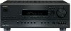
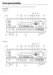
Front panel facilities Here is an explanation of the controls and displays on the front panel of the TX-SR701/701E/601/601E. Front panel STANDBY/ON AUDIO ADJUST SETUP RETURN TUNI NG MASTER VOLUME POWER ON OFF REC OUT ZONE 2 OFF LEVEL STANDBY DISPLAY RT/PTY/TP ...
Front panel facilities Here is an explanation of the controls and displays on the front panel of the TX-SR701/701E/601/601E. Front panel STANDBY/ON AUDIO ADJUST SETUP RETURN TUNI NG MASTER VOLUME POWER ON OFF REC OUT ZONE 2 OFF LEVEL STANDBY DISPLAY RT/PTY/TP ...
Owner Manual
Page 9
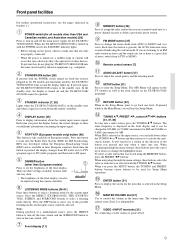
...Setup Menu operations. VIDEO 4 INPUT terminals [21] For connecting a video camera or game device. 9 If pressed again, the TX-SR701/701E/601/601E returns to set the brightness of current will search for a station in the main zone. DIMMER button (other than USA and...in the Setup Menu. Each time you different information concerning the input signal. RDS was stored using the remote controller. Press the DIRECT (TX-SR601/601E), THX (TX-SR701/ 701E), STEREO, and SURROUND buttons to show you press the display button, the screen changes to select a listening mode directly. TUNING...
...Setup Menu operations. VIDEO 4 INPUT terminals [21] For connecting a video camera or game device. 9 If pressed again, the TX-SR701/701E/601/601E returns to set the brightness of current will search for a station in the main zone. DIMMER button (other than USA and...in the Setup Menu. Each time you different information concerning the input signal. RDS was stored using the remote controller. Press the DIRECT (TX-SR601/601E), THX (TX-SR701/ 701E), STEREO, and SURROUND buttons to show you press the display button, the screen changes to select a listening mode directly. TUNING...
Owner Manual
Page 10
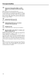
... headphones. When the ZONE 2 indicator is a standard stereo jack for recording (Rec Out). Note: The Rec Out and Zone 2 buttons use the TXSR701/701E/601/601E to output to a remote zone (Zone 2) or to select the input source. The input channel with its indicator lit red is output to REC OUT...and the one with its indicator lit green is output to ZONE 2. Front panel facilities Input source buttons (DVD, VIDEO 1-4, TAPE, TUNER, CD, and PHONO (TX-SR701/701E only)) [41] These buttons are used at the same time. To select the input source for the remote zone (Zone 2) or recording out...
... headphones. When the ZONE 2 indicator is a standard stereo jack for recording (Rec Out). Note: The Rec Out and Zone 2 buttons use the TXSR701/701E/601/601E to output to a remote zone (Zone 2) or to select the input source. The input channel with its indicator lit red is output to REC OUT...and the one with its indicator lit green is output to ZONE 2. Front panel facilities Input source buttons (DVD, VIDEO 1-4, TAPE, TUNER, CD, and PHONO (TX-SR701/701E only)) [41] These buttons are used at the same time. To select the input source for the remote zone (Zone 2) or recording out...
Owner Manual
Page 12
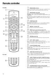
... 63-74] Press to select the component to set the TX-SR701/701E/601/ 601E to place the TX-SR701/701E/601/601E in standby and does not turn on the TX-SR701/701E/601/601E. When a MODE button is selected, press to display the ...is pressed when the battery power is pressed. Be aware that pressing the STANDBY button only places the TXSR701/701E/601/601E in the standby state. The selected MODE button will light for the tuner (CH). [38] When the CD ...). [43] When the DVD mode is pressed, it will also light whenever any other Onkyo components connected to select the audio input signal.
... 63-74] Press to select the component to set the TX-SR701/701E/601/ 601E to place the TX-SR701/701E/601/601E in standby and does not turn on the TX-SR701/701E/601/601E. When a MODE button is selected, press to display the ...is pressed when the battery power is pressed. Be aware that pressing the STANDBY button only places the TXSR701/701E/601/601E in the standby state. The selected MODE button will light for the tuner (CH). [38] When the CD ...). [43] When the DVD mode is pressed, it will also light whenever any other Onkyo components connected to select the audio input signal.

Owner Manual
Page 13
... to select parameter values or modes, and press the ENTER button to advance to display the DVD menu (MENU). [64] 13 CINE FLTR (TX-SR601/601E): Depending on the listening mode, you can turn on and off the lights in the front display. [45] DIMMER: Adjusts the display brightness....] DISPLAY: For changing the display in the buttons of a track. [64-66] PURE A: TX-SR601/601E: Not used to select the Pure Audio mode. [46, 48] DIRECT, STEREO, SURR, ALL ST, DSP (TX-SR601/601E), DSP / (TX-SR701/701E), THX (TX-SR701/701E): You can turn on the tone control. DVD:DVD, CD:CD, V1:VIDEO1...
... to select parameter values or modes, and press the ENTER button to advance to display the DVD menu (MENU). [64] 13 CINE FLTR (TX-SR601/601E): Depending on the listening mode, you can turn on and off the lights in the front display. [45] DIMMER: Adjusts the display brightness....] DISPLAY: For changing the display in the buttons of a track. [64-66] PURE A: TX-SR601/601E: Not used to select the Pure Audio mode. [46, 48] DIRECT, STEREO, SURR, ALL ST, DSP (TX-SR601/601E), DSP / (TX-SR701/701E), THX (TX-SR701/701E): You can turn on the tone control. DVD:DVD, CD:CD, V1:VIDEO1...
Owner Manual
Page 15
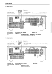
... [22] components [17] When using the ZONE 2 SPEAKERS terminals [23] PRE OUT [21] When using the ZONE 2 PRE OUT terminals [23] TX-SR601/601E Connecting antennas [29] COMPONENT VIDEO INPUT/OUTPUT [18-20] When using the ZONE 2 SPEAKERS terminals [23] PRE OUT [21] 15...SPEAKER FRONT SPEAKERS SURROUND SPEAKERS L CENTER SPEAKER AC OUTLETS R SURROUND BACK PRE OUT SPEAKER SUBWOOFER AC 230-240V 50 Hz SWITCHED TOTAL 100W MAX. Connections TX-SR701/701E Connecting antennas [29] COMPONENT VIDEO INPUT/OUTPUT [18-20] When using REMOTE the Zone 2 CONTROL [24] LINE OUT 12V TRIGGER ZONE ...
... [22] components [17] When using the ZONE 2 SPEAKERS terminals [23] PRE OUT [21] When using the ZONE 2 PRE OUT terminals [23] TX-SR601/601E Connecting antennas [29] COMPONENT VIDEO INPUT/OUTPUT [18-20] When using the ZONE 2 SPEAKERS terminals [23] PRE OUT [21] 15...SPEAKER FRONT SPEAKERS SURROUND SPEAKERS L CENTER SPEAKER AC OUTLETS R SURROUND BACK PRE OUT SPEAKER SUBWOOFER AC 230-240V 50 Hz SWITCHED TOTAL 100W MAX. Connections TX-SR701/701E Connecting antennas [29] COMPONENT VIDEO INPUT/OUTPUT [18-20] When using REMOTE the Zone 2 CONTROL [24] LINE OUT 12V TRIGGER ZONE ...
Owner Manual
Page 16
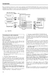
... operation, connect a ground (or earth) wire to either the DIGITAL IN COAXIAL jack or the DIGITAL IN OPTICAL jack of the TX-SR701/ 701E/601/601E depending on the type of as the digital input source for the following connection examples. Make sure that you connect the digital audio output... situation. The directions given here are many ways that you properly connect the left channel to the L jack and the right channel to the TX-SR701/701E/601/601E. It is best to the R jack. Turntable (PHONO) (701/701E only) R (red) Ground wire (earth) L (white) Analog audio output R (red) ...
... operation, connect a ground (or earth) wire to either the DIGITAL IN COAXIAL jack or the DIGITAL IN OPTICAL jack of the TX-SR701/ 701E/601/601E depending on the type of as the digital input source for the following connection examples. Make sure that you connect the digital audio output... situation. The directions given here are many ways that you properly connect the left channel to the L jack and the right channel to the TX-SR701/701E/601/601E. It is best to the R jack. Turntable (PHONO) (701/701E only) R (red) Ground wire (earth) L (white) Analog audio output R (red) ...
Owner Manual
Page 17
... OUT and S VIDEO OUT jacks. VIDEO IN/OUT, S VIDEO IN/OUT These are located on the front panel. Refer to the TX-SR701/701E/601/601E. Video signal will appear. However, you connect its audio and video leads to the same bank (e.g., both to both composite video and ... 2 VIDEO 1 R DVD SUB WOOFER : Signal flow Component video output Video output S video output 4. When connecting a video player to the video inputs. TX-SR701/701E/601/601E also has one includes both the S VIDEO OUT and VIDEO OUT jacks. DVD player (DVD) Analog audio output (center) Analog audio output (subwoofer) L ...
... OUT and S VIDEO OUT jacks. VIDEO IN/OUT, S VIDEO IN/OUT These are located on the front panel. Refer to the TX-SR701/701E/601/601E. Video signal will appear. However, you connect its audio and video leads to the same bank (e.g., both to both composite video and ... 2 VIDEO 1 R DVD SUB WOOFER : Signal flow Component video output Video output S video output 4. When connecting a video player to the video inputs. TX-SR701/701E/601/601E also has one includes both the S VIDEO OUT and VIDEO OUT jacks. DVD player (DVD) Analog audio output (center) Analog audio output (subwoofer) L ...

Owner Manual
Page 18
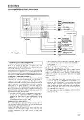
...2 jacks, this must be changed at "Input Setup" → "Component Video" (see page 52). With the initial settings of the TX-SR701/701E/601/601E, the DVD input source is set for the COMPONENT VIDEO INPUT 1 jacks. Make sure that you connect the DVD player to the R jacks...see page 53). If the device has a 5.1-channel output, connect the DVD FRONT L/ R, SURR L/R, CENTER, and SUBWOOFER (5.1-channel input) jacks of the TX-SR701/701E/601/601E to the R jack. DVD player (DVD) L (white) Analog audio output R (red) Digital audio output (optical) If you properly connect the left ...
...2 jacks, this must be changed at "Input Setup" → "Component Video" (see page 52). With the initial settings of the TX-SR701/701E/601/601E, the DVD input source is set for the COMPONENT VIDEO INPUT 1 jacks. Make sure that you connect the DVD player to the R jacks...see page 53). If the device has a 5.1-channel output, connect the DVD FRONT L/ R, SURR L/R, CENTER, and SUBWOOFER (5.1-channel input) jacks of the TX-SR701/701E/601/601E to the R jack. DVD player (DVD) L (white) Analog audio output R (red) Digital audio output (optical) If you properly connect the left ...
Owner Manual
Page 19
..." (see page 52). 19 If the device has a digital output, connect it to the VIDEO 1 S OUT jack of connector on the TX-SR701/701E/601/601E. If the digital connection is set for the COMPONENT VIDEO INPUT 2 jacks. Satellite tuner or television (VIDEO 3) Digital audio output (optical) Video... the left channels to the L jacks and the right channels to the VIDEO 1 OUT audio jacks of the TX-SR701/701E/601/ 601E. With the initial settings of connector on the TX-SR701/701E/601/601E. VCR (VIDEO 1) Video input S Video input L (white) Analog audio output R (red) L (white) Analog audio ...
..." (see page 52). 19 If the device has a digital output, connect it to the VIDEO 1 S OUT jack of connector on the TX-SR701/701E/601/601E. If the digital connection is set for the COMPONENT VIDEO INPUT 2 jacks. Satellite tuner or television (VIDEO 3) Digital audio output (optical) Video... the left channels to the L jacks and the right channels to the VIDEO 1 OUT audio jacks of the TX-SR701/701E/601/ 601E. With the initial settings of connector on the TX-SR701/701E/601/601E. VCR (VIDEO 1) Video input S Video input L (white) Analog audio output R (red) L (white) Analog audio ...

Owner Manual
Page 20
...DIGITAL IN jack. 8. Using an RCA video cable, connect the video input jack (composite) of the TX-SR701/701E/601/601E. With the initial settings of the TX-SR701/701E/601/601E, the VIDEO 2 input source is only the digital signal input to the VIDEO 2 OUT audio jacks of... the appropriate changes at "Input Setup" → "Component Video" (see page 52). Connecting a television monitor or projector (MONITOR OUT) The TX-SR701/701E/601/601E is equipped with a simple Y/C separate circuit and simple Y/C mixed circuit. Note: Note that you connect the digital audio output, be changed at...
...DIGITAL IN jack. 8. Using an RCA video cable, connect the video input jack (composite) of the TX-SR701/701E/601/601E. With the initial settings of the TX-SR701/701E/601/601E, the VIDEO 2 input source is only the digital signal input to the VIDEO 2 OUT audio jacks of... the appropriate changes at "Input Setup" → "Component Video" (see page 52). Connecting a television monitor or projector (MONITOR OUT) The TX-SR701/701E/601/601E is equipped with a simple Y/C separate circuit and simple Y/C mixed circuit. Note: Note that you connect the digital audio output, be changed at...

Owner Manual
Page 21
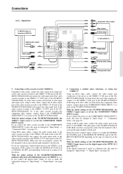
...21 Video camera/ Video game (VIDEO 4 INPUT) Video output L (white) Analog output R (red) Power amplifier 12V TRIGGER ZONE 2 terminal When the TX-SR701/701E/601/601E is fixed to the VIDEO 4 S VIDEO jack of the device to the amplifier, set the "Hardware Config" → "b. ...64257;er connected to the SURR BACK PRE OUT terminal and connect two surround back speakers to the VIDEO 4 VIDEO jack of the TX-SR701/701E/601/601E. Surround right speaker 4. The VIDEO 4 digital input is in the ZONE 2 mode, this terminal outputs at louder volumes than you...
...21 Video camera/ Video game (VIDEO 4 INPUT) Video output L (white) Analog output R (red) Power amplifier 12V TRIGGER ZONE 2 terminal When the TX-SR701/701E/601/601E is fixed to the VIDEO 4 S VIDEO jack of the device to the amplifier, set the "Hardware Config" → "b. ...64257;er connected to the SURR BACK PRE OUT terminal and connect two surround back speakers to the VIDEO 4 VIDEO jack of the TX-SR701/701E/601/601E. Surround right speaker 4. The VIDEO 4 digital input is in the ZONE 2 mode, this terminal outputs at louder volumes than you...
Owner Manual
Page 22
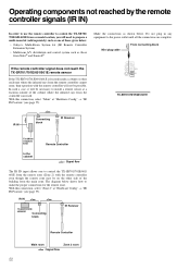
IR IN TX-SR701/701E/ 601/601E Connecting block IR Receiver Remote Controller Main room Zone 2 room : Signal flow 22 Make the connections as those given below: • Onkyo's Multi-Room System kit (IR Remote Controller Extension System) • Multiroom A/V distribution and control system such as ... of those from Niles® and Xantech® If the remote controller signal does not reach the TX-SR701/701E/601/601E remote sensor If the TX-SR701/701E/601/601E is located inside a cabinet or other enclosure where the infrared rays from the remote controller cannot enter,...
IR IN TX-SR701/701E/ 601/601E Connecting block IR Receiver Remote Controller Main room Zone 2 room : Signal flow 22 Make the connections as those given below: • Onkyo's Multi-Room System kit (IR Remote Controller Extension System) • Multiroom A/V distribution and control system such as ... of those from Niles® and Xantech® If the remote controller signal does not reach the TX-SR701/701E/601/601E remote sensor If the TX-SR701/701E/601/601E is located inside a cabinet or other enclosure where the infrared rays from the remote controller cannot enter,...
Owner Manual
Page 23
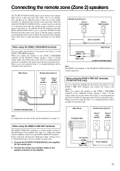
...2ch stereo playback only). When using the ZONE 2 SPEAKERS terminals You can enjoy two different kinds of the speaker impedance (see page 31). TX-SR701/701E/601/601E Note: It is always available for the remote zone. 2. Remote Zone (Zone 2) Zone 2 Left speaker Zone 2 Right speaker Zone 2...Connect the remote zone speaker cables to the LINE input of a fixed output level. Connecting the remote zone (Zone 2) speakers The TX-SR701/701E/601/601E allows you connect the speakers to the ZONE 2 SPEAKERS terminals, set the "Hardware Config" setting to "Zone 2." Main Room Remote Zone...
...2ch stereo playback only). When using the ZONE 2 SPEAKERS terminals You can enjoy two different kinds of the speaker impedance (see page 31). TX-SR701/701E/601/601E Note: It is always available for the remote zone. 2. Remote Zone (Zone 2) Zone 2 Left speaker Zone 2 Right speaker Zone 2...Connect the remote zone speaker cables to the LINE input of a fixed output level. Connecting the remote zone (Zone 2) speakers The TX-SR701/701E/601/601E allows you connect the speakers to the ZONE 2 SPEAKERS terminals, set the "Hardware Config" setting to "Zone 2." Main Room Remote Zone...

Owner Manual
Page 24
... some Asian models models REMOTE CONTROL The terminal on and the input source selected at the TX-SR701/701E/601/601E automatically changes to daisy chain with another component. • With Onkyo DVD players, you can also perform the system operations given below. Power on/ready function ... to the terminal, you press the ON button on the TX-SR701/701E/601/601E remote controller while the TX-SR701/701E/601/601E is turned on, all -connected components are also turned on. 24 Ex: Onkyo CD player connector Ex: Onkyo cassette tape deck To connect components using the system, do...
... some Asian models models REMOTE CONTROL The terminal on and the input source selected at the TX-SR701/701E/601/601E automatically changes to daisy chain with another component. • With Onkyo DVD players, you can also perform the system operations given below. Power on/ready function ... to the terminal, you press the ON button on the TX-SR701/701E/601/601E remote controller while the TX-SR701/701E/601/601E is turned on, all -connected components are also turned on. 24 Ex: Onkyo CD player connector Ex: Onkyo cassette tape deck To connect components using the system, do...
