Owner Manual
Page 5
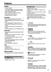
...*6 Neural Surround name and related logos are trademarks owned by Neural Audio Corporation. *7 XM Ready® is a trademark of Onkyo Corporation. *5 HDMI, the HDMI logo and High Definition Multimedia Interface are trademarks or registered trademarks of DTS, Inc....RDS (Radio Data System) (Europe only) Remote Controller • Preprogrammed for use with other AV components TX-SR505 North American model/ TX-SR505E Only • 2 HDMI*5 inputs, 1 output TX-SR575 Only • 2 HDMI*5 inputs, 1 output • Composite video and S-Video to component video conversion • Composite video...
...*6 Neural Surround name and related logos are trademarks owned by Neural Audio Corporation. *7 XM Ready® is a trademark of Onkyo Corporation. *5 HDMI, the HDMI logo and High Definition Multimedia Interface are trademarks or registered trademarks of DTS, Inc....RDS (Radio Data System) (Europe only) Remote Controller • Preprogrammed for use with other AV components TX-SR505 North American model/ TX-SR505E Only • 2 HDMI*5 inputs, 1 output TX-SR575 Only • 2 HDMI*5 inputs, 1 output • Composite video and S-Video to component video conversion • Composite video...
Owner Manual
Page 6
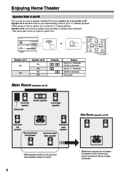
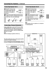
Speaker set A should be used in another room and offers 2-channel stereo playback. *Only analog input sources are not output by speaker set B. Enjoying Home Theater Speaker Sets A and B You can be used in your source component with the AV receiver: speaker set A and speaker set B. STANDBY/ON STANDBY PHONES A SPEAKETRUNSING BPRESET MASTER VOLUME...
Speaker set A should be used in another room and offers 2-channel stereo playback. *Only analog input sources are not output by speaker set B. Enjoying Home Theater Speaker Sets A and B You can be used in your source component with the AV receiver: speaker set A and speaker set B. STANDBY/ON STANDBY PHONES A SPEAKETRUNSING BPRESET MASTER VOLUME...

Owner Manual
Page 7
... Onkyo Components 33 Connecting the Power Cord 33 Turning On & First Time Setup Turning On the AV Receiver 34 First Time Setup 35 Automatic Speaker Setup (Audyssey 2EQ 35 Video Input Setup (TX-SR505 North American Model/ TX-SR505E/TX-SR575 Only 38 Digital Audio Input Setup 39 Changing the Input Display 39 Basic Operation Playing Your AV Components 40 Basic AV Receiver...
... Onkyo Components 33 Connecting the Power Cord 33 Turning On & First Time Setup Turning On the AV Receiver 34 First Time Setup 35 Automatic Speaker Setup (Audyssey 2EQ 35 Video Input Setup (TX-SR505 North American Model/ TX-SR505E/TX-SR575 Only 38 Digital Audio Input Setup 39 Changing the Input Display 39 Basic Operation Playing Your AV Components 40 Basic AV Receiver...

Owner Manual
Page 8
... is selected, the TUNING [ ] [ ] buttons are used for connecting a standard pair of the AV receiver to On or Standby. E Input selector buttons (40) Select the input sources. I SPEAKERS A and B buttons (6, 40) Turn speaker sets A and B on page 9. Getting to Know the AV Receiver Front Panel North American Model 12 3 45 6 STANDBY/ON STANDBY TUNING PRESET 7 MASTER...
... is selected, the TUNING [ ] [ ] buttons are used for connecting a standard pair of the AV receiver to On or Standby. E Input selector buttons (40) Select the input sources. I SPEAKERS A and B buttons (6, 40) Turn speaker sets A and B on page 9. Getting to Know the AV Receiver Front Panel North American Model 12 3 45 6 STANDBY/ON STANDBY TUNING PRESET 7 MASTER...

Owner Manual
Page 9
... lights up when speaker set A is muted. 3 Input signal format indicators Show the audio signal format of digital input signals. Indicator B lights up when the Sleep function has been set B is on. 2 MUTING indicator (46) Flashes while the AV receiver is on. TUNED (42): Lights up when tuned to...radio station. 6 SLEEP indicator (47) Lights up when speaker set . 7 Message area Displays various information about the currently selected input source. Getting to Know the AV Receiver-Continued J TONE, [-], and [+] buttons (46) Used to a radio station that supports RDS (Radio Data System).
... lights up when speaker set A is muted. 3 Input signal format indicators Show the audio signal format of digital input signals. Indicator B lights up when the Sleep function has been set B is on. 2 MUTING indicator (46) Flashes while the AV receiver is on. TUNED (42): Lights up when tuned to...radio station. 6 SLEEP indicator (47) Lights up when speaker set . 7 Message area Displays various information about the currently selected input source. Getting to Know the AV Receiver-Continued J TONE, [-], and [+] buttons (46) Used to a radio station that supports RDS (Radio Data System).

Owner Manual
Page 11
... (TX-SR575 North American model only) This jack is for connecting an AM antenna. To use , you must make an analog audio connection (RCA) between the AV receiver and the other component that supports component video can be connected to a video input on another -capable Onkyo com... This analog audio input is for connecting a CD player's analog audio output. G SIRIUS antenna (TX-SR575 North American model only) This jack is for connecting a SIRIUS Satellite Radio antenna (see page 3). B HDMI IN 1, 2, and OUT (TX-SR505 North American model/TX-SR505E/ TX-SR575 only) These...
... (TX-SR575 North American model only) This jack is for connecting an AM antenna. To use , you must make an analog audio connection (RCA) between the AV receiver and the other component that supports component video can be connected to a video input on another -capable Onkyo com... This analog audio input is for connecting a CD player's analog audio output. G SIRIUS antenna (TX-SR575 North American model only) This jack is for connecting a SIRIUS Satellite Radio antenna (see page 3). B HDMI IN 1, 2, and OUT (TX-SR505 North American model/TX-SR505E/ TX-SR575 only) These...

Owner Manual
Page 12
...control up to seven different components. By entering the appropriate DOCK remote control code, you can control the AV receiver and an Onkyo cassette recorder connected via . 1 2 3 1 4 2 5 3 6 7 4 8 9 J STANDBY/ON REMOTE MODE RECEIVER DVD TAPE/AMP INPUT SELECTOR M D/CDR 1 2 3 VCR/DVR CBL/SAT C D DOCK 4 5 6 TV AUX...Using the Remote Controller Including the AV receiver, the remote controller can be used to control an Onkyo cassette recorder connected via . Modes are used when the TUNER or TAPE input is used to control the AV receiver. The remote controller has a speci...
...control up to seven different components. By entering the appropriate DOCK remote control code, you can control the AV receiver and an Onkyo cassette recorder connected via . 1 2 3 1 4 2 5 3 6 7 4 8 9 J STANDBY/ON REMOTE MODE RECEIVER DVD TAPE/AMP INPUT SELECTOR M D/CDR 1 2 3 VCR/DVR CBL/SAT C D DOCK 4 5 6 TV AUX...Using the Remote Controller Including the AV receiver, the remote controller can be used to control an Onkyo cassette recorder connected via . Modes are used when the TUNER or TAPE input is used to control the AV receiver. The remote controller has a speci...

Owner Manual
Page 13
... Surround listening mode (TX-SR575 North American model only). [ ]/[ ] buttons Used to select the input sources. L SLEEP button (47) Used with the Late Night function. ■ Buttons used when the TAPE input is selected To select the Tuner (AM/FM) as the input source, press: RECEIVER 7 TAPE 4 Playback... FM, the Up and Down [ ]/[ ] buttons are used for the currently selected mode lights up. N MUTING button (46) Mutes or unmutes the AV receiver. P CINE FLTR button (52) Used with the CinemaFILTER function. Stop [ ] button Stops playback. G SETUP button Used to select AM and FM radio...
... Surround listening mode (TX-SR575 North American model only). [ ]/[ ] buttons Used to select the input sources. L SLEEP button (47) Used with the Late Night function. ■ Buttons used when the TAPE input is selected To select the Tuner (AM/FM) as the input source, press: RECEIVER 7 TAPE 4 Playback... FM, the Up and Down [ ]/[ ] buttons are used for the currently selected mode lights up. N MUTING button (46) Mutes or unmutes the AV receiver. P CINE FLTR button (52) Used with the CinemaFILTER function. Stop [ ] button Stops playback. G SETUP button Used to select AM and FM radio...
Owner Manual
Page 14
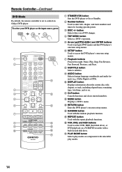
... NIGHT VCR DVD CINE FLTR HDD RC-681M DVD K L M N O P Q A STANDBY/ON button Sets the DVD player to control an Onkyo DVD player. J DISPLAY button Displays information about the current disc, title, chapter, or track, including elapsed time, remaining time, total time, and so... on a DVD changer. To select your DVD player as the input source, press: RECEIVER 6 DVD or 5 MULTI CH 1 2 3 4 5 6 7 8 9 J STANDBY/ON REMOTE MODE RECEIVER DVD TAPE/AMP INPUT SELECTOR M D/CDR 1 2 3 VCR/DVR CBL/SAT C D DOCK 4 5 6 TV AUX MULTI CH...
... NIGHT VCR DVD CINE FLTR HDD RC-681M DVD K L M N O P Q A STANDBY/ON button Sets the DVD player to control an Onkyo DVD player. J DISPLAY button Displays information about the current disc, title, chapter, or track, including elapsed time, remaining time, total time, and so... on a DVD changer. To select your DVD player as the input source, press: RECEIVER 6 DVD or 5 MULTI CH 1 2 3 4 5 6 7 8 9 J STANDBY/ON REMOTE MODE RECEIVER DVD TAPE/AMP INPUT SELECTOR M D/CDR 1 2 3 VCR/DVR CBL/SAT C D DOCK 4 5 6 TV AUX MULTI CH...

Owner Manual
Page 15
... or 2 RI Dock CBL/SAT * If you're using an MD, CDR, or an RI Dock, you must change the Input Display (see page 39). 1 2 3 4 5 6 7 STANDBY/ON REMOTE MODE RECEIVER DVD TAPE/AMP INPUT SELECTOR M D/CDR 1 2 3 VCR/DVR CBL/SAT C D DOCK 4 5 6 TV AUX MULTI CH DVD 7 8 9 VCR TAPE TUNER 10 11 +10 ...- LEVEL+ PLAY MODE DISPLAY L NIGHT VCR DVD CINE FLTR HDD RC-681M K L M A STANDBY/ON button Sets the component to control an Onkyo CD player. F Playback buttons From left to an RI Dock, it turns on the back light for locating specific points on an HDD-compatible...
... or 2 RI Dock CBL/SAT * If you're using an MD, CDR, or an RI Dock, you must change the Input Display (see page 39). 1 2 3 4 5 6 7 STANDBY/ON REMOTE MODE RECEIVER DVD TAPE/AMP INPUT SELECTOR M D/CDR 1 2 3 VCR/DVR CBL/SAT C D DOCK 4 5 6 TV AUX MULTI CH DVD 7 8 9 VCR TAPE TUNER 10 11 +10 ...- LEVEL+ PLAY MODE DISPLAY L NIGHT VCR DVD CINE FLTR HDD RC-681M K L M A STANDBY/ON button Sets the component to control an Onkyo CD player. F Playback buttons From left to an RI Dock, it turns on the back light for locating specific points on an HDD-compatible...
Owner Manual
Page 19
...insert the wire into the hole, and then release the lever. Connecting a Powered Subwoofer Using a suitable cable, connect the AV receiver's SUBWOOFER PRE OUT to the left (L) SURROUND BACK SPEAKERS terminals. Make sure that it's touching the threaded shaft in all ...BACK SPEAKERS L SURROUND SPEAKERS FRONT SPEAKERS A L CENTER SPEAKER R R Front right Front left speaker speaker Speaker Set B LINE INPUT Powered subwoofer Surround back right speaker Surround back left speaker Surround right speaker Surround left speaker The following illustration shows which speaker ...
...insert the wire into the hole, and then release the lever. Connecting a Powered Subwoofer Using a suitable cable, connect the AV receiver's SUBWOOFER PRE OUT to the left (L) SURROUND BACK SPEAKERS terminals. Make sure that it's touching the threaded shaft in all ...BACK SPEAKERS L SURROUND SPEAKERS FRONT SPEAKERS A L CENTER SPEAKER R R Front right Front left speaker speaker Speaker Set B LINE INPUT Powered subwoofer Surround back right speaker Surround back left speaker Surround right speaker Surround left speaker The following illustration shows which speaker ...
Owner Manual
Page 22
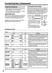
... used instead of a multichannel cable. The audio quality is the same as for coaxial. Note: The AV receiver does not support SCART connections. 22 AV Cables and Jacks AV Connection Color Coding RCA-type AV connections are usually color coded: red, white, and yellow. Left (white) Analog audio Left (white)... cables. This offers the best sound quality and allows you 've completed and double-checked all the way to connect composite video inputs and outputs. This cable carries analog audio. This cable carries multichannel analog audio and is inserted and close when it's removed. Caution...
... used instead of a multichannel cable. The audio quality is the same as for coaxial. Note: The AV receiver does not support SCART connections. 22 AV Cables and Jacks AV Connection Color Coding RCA-type AV connections are usually color coded: red, white, and yellow. Left (white) Analog audio Left (white)... cables. This offers the best sound quality and allows you 've completed and double-checked all the way to connect composite video inputs and outputs. This cable carries analog audio. This cable carries multichannel analog audio and is inserted and close when it's removed. Caution...

Owner Manual
Page 23
... video components, such as a guide. Video Signal Flow Chart TX-SR505/TX-SR505E/TX-SR8550 DVD player, etc. Use the following sections as a DVD player, you can be connected to the AV receiver by using any one of the same format as the input will depend on the AV receiver. : Signal Flow Video Video Audio Audio DVD player, etc...
... video components, such as a guide. Video Signal Flow Chart TX-SR505/TX-SR505E/TX-SR8550 DVD player, etc. Use the following sections as a DVD player, you can be connected to the AV receiver by using any one of the same format as the input will depend on the AV receiver. : Signal Flow Video Video Audio Audio DVD player, etc...
Owner Manual
Page 24
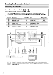
...or cable or satellite receiver to the AV receiver and use a and b , or a and c .) Connection A B C a b c AV receiver COMPONENT VIDEO OUT MONITOR OUT S MONITOR OUT V CBL/SAT IN L/R DIGITAL IN COAXIAL 2 DIGITAL IN OPTICAL 1 Signal flow TV Component video input S-Video input Composite video input Analog audio L/R ...B , and C . Step 2: Choose an audio connection from a , b , and c . • With connection a , you can listen to TV programs through the AV receiver (see page 39) TV, projector, etc. IAL 1 Y (DVD) 2 (CBL/SAT) OPTICAL 1 (VCR/DVR) 2 (CD) CB/PB CR/PR CBL/SAT IN VCR...
...or cable or satellite receiver to the AV receiver and use a and b , or a and c .) Connection A B C a b c AV receiver COMPONENT VIDEO OUT MONITOR OUT S MONITOR OUT V CBL/SAT IN L/R DIGITAL IN COAXIAL 2 DIGITAL IN OPTICAL 1 Signal flow TV Component video input S-Video input Composite video input Analog audio L/R ...B , and C . Step 2: Choose an audio connection from a , b , and c . • With connection a , you can listen to TV programs through the AV receiver (see page 39) TV, projector, etc. IAL 1 Y (DVD) 2 (CBL/SAT) OPTICAL 1 (VCR/DVR) 2 (CD) CB/PB CR/PR CBL/SAT IN VCR...
Owner Manual
Page 26
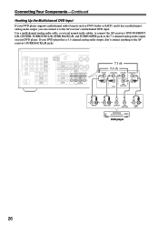
... has a multichannel analog audio output, you can connect it to the AV receiver's multichannel DVD input. DIGITAL IN ASSIGNABLE COAX- Connecting Your Components-Continued Hooking Up the Multichannel DVD Input If your DVD player has a 5.1-channel analog audio output, don't connect anything to the AV receiver's SURR BACK L/R jacks. Use a multichannel analog audio cable, or several...
... has a multichannel analog audio output, you can connect it to the AV receiver's multichannel DVD input. DIGITAL IN ASSIGNABLE COAX- Connecting Your Components-Continued Hooking Up the Multichannel DVD Input If your DVD player has a 5.1-channel analog audio output, don't connect anything to the AV receiver's SURR BACK L/R jacks. Use a multichannel analog audio cable, or several...

Owner Manual
Page 27
...HDMI OUT. • The HDMI video stream is compatible with DVI (Digital Visual Interface), so TVs and displays with a DVI input can connect it to the AV receiver with such an adapter is not guaranteed. If you make a separate analog or digital audio connection. Refer to the...Connecting Your Components-Continued TX-SR505 North American Model/TX-SR505E/TX-SR575 Only Connecting Components with HDMI If you have an HDMI-compatible player, you can be connected by using an HDMI-to-DVI adapter cable. (Note that 's connected via the AV receiver's HDMI jacks, the AV receiver must be restricted by ...
...HDMI OUT. • The HDMI video stream is compatible with DVI (Digital Visual Interface), so TVs and displays with a DVI input can connect it to the AV receiver with such an adapter is not guaranteed. If you make a separate analog or digital audio connection. Refer to the...Connecting Your Components-Continued TX-SR505 North American Model/TX-SR505E/TX-SR575 Only Connecting Components with HDMI If you have an HDMI-compatible player, you can be connected by using an HDMI-to-DVI adapter cable. (Note that 's connected via the AV receiver's HDMI jacks, the AV receiver must be restricted by ...

Owner Manual
Page 29
...AV receiver AUX INPUT VIDEO AUX INPUT L-AUDIO-R Signal flow ⇐ ⇐ Camcorder or console Composite video output Analog audio L/R output 29 Connecting Your Components-Continued Connecting a VCR or DVD Recorder for Recording Step 1: Choose a video connection from A and B . TX-SR505/TX-SR505E/TX-SR8550: The video source to be recorded must be connected to the AV receiver... VIDEO IN AV receiver VCR/DVR OUT S VCR/DVR OUT V VCR/DVR OUT L/R Signal flow ⇒ ⇒ ⇒ VCR or DVD recorder S-Video input Composite video input Analog audio L/R input Picture quality ...
...AV receiver AUX INPUT VIDEO AUX INPUT L-AUDIO-R Signal flow ⇐ ⇐ Camcorder or console Composite video output Analog audio L/R output 29 Connecting Your Components-Continued Connecting a VCR or DVD Recorder for Recording Step 1: Choose a video connection from A and B . TX-SR505/TX-SR505E/TX-SR8550: The video source to be recorded must be connected to the AV receiver... VIDEO IN AV receiver VCR/DVR OUT S VCR/DVR OUT V VCR/DVR OUT L/R Signal flow ⇒ ⇒ ⇒ VCR or DVD recorder S-Video input Composite video input Analog audio L/R input Picture quality ...
Owner Manual
Page 31
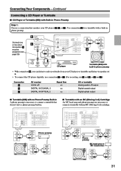
... • To connect the CD player digitally, use connection b or c . (For recording, use a and b , or a and c .) Connection a b c AV receiver CD IN L/R DIGITAL IN COAXIAL 2 DIGITAL IN OPTICAL 2 Signal flow ⇐ ⇐ ⇐ CD or turntable Analog audio L/R output Digital coaxial output Digital ...SURROUND CENTER SURR BACK L R CBL/SAT VCR/DVR R SUB WOOFER DVD IN L R CD AUDIO OUTPUT L R Phono preamp AUDIO OUTPUT L R AUDIO INPUT L R ■ Turntable with an MC (Moving Coil) Cartridge An MC head amp and phono preamp are necessary to connect a turntable that matches your ...
... • To connect the CD player digitally, use connection b or c . (For recording, use a and b , or a and c .) Connection a b c AV receiver CD IN L/R DIGITAL IN COAXIAL 2 DIGITAL IN OPTICAL 2 Signal flow ⇐ ⇐ ⇐ CD or turntable Analog audio L/R output Digital coaxial output Digital ...SURROUND CENTER SURR BACK L R CBL/SAT VCR/DVR R SUB WOOFER DVD IN L R CD AUDIO OUTPUT L R Phono preamp AUDIO OUTPUT L R AUDIO INPUT L R ■ Turntable with an MC (Moving Coil) Cartridge An MC head amp and phono preamp are necessary to connect a turntable that matches your ...

Owner Manual
Page 32
...see page 39). • Refer to the AV receiver's TAPE IN L/R jacks (1). R R IN OUT REC PLAY Connection a b c AV receiver TAPE IN L/R TAPE OUT L/R DIGITAL IN COAXIAL 2 DIGITAL IN OPTICAL 1 Signal flow Cassette/CDR/MD/DAT recorder Analog audio L/R output Analog audio L/R input Digital coaxial output Digital optical output 32 S ...cable (see page 33). • Set the Remote Interactive Dock's RI MODE switch to HDD or HDD/DOCK. • Set the AV receiver's Input Display to DOCK (see page 39) b COAXIAL 2 (CBL/SAT) c OPTICAL 1 (VCR/DVR) COAXIAL OUT DIGITAL IN ASSIGNABLE COAX-
...see page 39). • Refer to the AV receiver's TAPE IN L/R jacks (1). R R IN OUT REC PLAY Connection a b c AV receiver TAPE IN L/R TAPE OUT L/R DIGITAL IN COAXIAL 2 DIGITAL IN OPTICAL 1 Signal flow Cassette/CDR/MD/DAT recorder Analog audio L/R output Analog audio L/R input Digital coaxial output Digital optical output 32 S ...cable (see page 33). • Set the Remote Interactive Dock's RI MODE switch to HDD or HDD/DOCK. • Set the AV receiver's Input Display to DOCK (see page 39) b COAXIAL 2 (CBL/SAT) c OPTICAL 1 (VCR/DVR) COAXIAL OUT DIGITAL IN ASSIGNABLE COAX-

Owner Manual
Page 33
... a momentary power surge that might interfere with other electrical equipment on and select that component as the input source. Connecting Your Components-Continued Connecting Onkyo Components Step 1: Make sure that each Onkyo component is connected to the AV receiver with an analog audio cable (connection a in the hookup examples) (see page 41), as the Direct...
... a momentary power surge that might interfere with other electrical equipment on and select that component as the input source. Connecting Your Components-Continued Connecting Onkyo Components Step 1: Make sure that each Onkyo component is connected to the AV receiver with an analog audio cable (connection a in the hookup examples) (see page 41), as the Direct...


