Owner Manual
Page 1
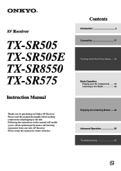
Contents Introduction 2 Connection 17 Turning On & First Time Setup..... 34 Basic Operation Playing your AV components ....... 40 Listening to obtain optimum performance and listening enjoyment from your new AV Receiver. AV Receiver TX-SR505 TX-SR505E TX-SR8550 TX-SR575 Instruction Manual Thank you to the Radio 42 Enjoying the Listening Modes ..... 48 Advanced Operation 55 Troubleshooting 65 En Please ... and plugging in this manual will enable you for future reference. Following the instructions in the unit. Please read this manual for purchasing an Onkyo AV Receiver.
Contents Introduction 2 Connection 17 Turning On & First Time Setup..... 34 Basic Operation Playing your AV components ....... 40 Listening to obtain optimum performance and listening enjoyment from your new AV Receiver. AV Receiver TX-SR505 TX-SR505E TX-SR8550 TX-SR575 Instruction Manual Thank you to the Radio 42 Enjoying the Listening Modes ..... 48 Advanced Operation 55 Troubleshooting 65 En Please ... and plugging in this manual will enable you for future reference. Following the instructions in the unit. Please read this manual for purchasing an Onkyo AV Receiver.
Owner Manual
Page 3
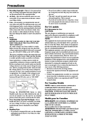
... top and rear panels may not work properly the next time you plug in your Onkyo dealer. 6. If this equipment does cause harmful interference to radio or television reception, which the receiver is readily operable (easily accessible) at all over with Wet Hands-Never handle this ...unit for your Onkyo dealer. 3. Precautions 1. Recording Copyright-Unless it . • Do not leave rubber or...
... top and rear panels may not work properly the next time you plug in your Onkyo dealer. 6. If this equipment does cause harmful interference to radio or television reception, which the receiver is readily operable (easily accessible) at all over with Wet Hands-Never handle this ...unit for your Onkyo dealer. 3. Precautions 1. Recording Copyright-Unless it . • Do not leave rubber or...

Owner Manual
Page 4
... -3-3. Fit a suitable fuse in certain countries. GROEBENZELL, GERMANY K. Use of this instruction manual is in compliance with the plug on the AV receiver's power cord. (Adapter varies from country to the terminal which is marked with the following code: Blue: Neutral Brown: Live As the ... AC plug on the plug. If the power cord's plug is marked with an appropriate fuse. MIYAGI ONKYO EUROPE ELECTRONICS GmbH TX-SR575 incorporates copyright protection technology that the ONKYO product described in the mains lead are the same regardless of color. 4 Front Left Front Left SP-B...
... -3-3. Fit a suitable fuse in certain countries. GROEBENZELL, GERMANY K. Use of this instruction manual is in compliance with the plug on the AV receiver's power cord. (Adapter varies from country to the terminal which is marked with the following code: Blue: Neutral Brown: Live As the ... AC plug on the plug. If the power cord's plug is marked with an appropriate fuse. MIYAGI ONKYO EUROPE ELECTRONICS GmbH TX-SR575 incorporates copyright protection technology that the ONKYO product described in the mains lead are the same regardless of color. 4 Front Left Front Left SP-B...
Owner Manual
Page 6
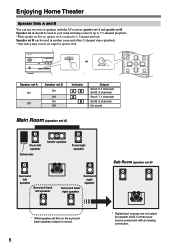
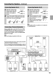
... playback. *While speaker set B is reduced to 5.1-channel playback. Enjoying Home Theater Speaker Sets A and B You can be used in your source component with the AV receiver: speaker set A and speaker set B. Speaker set A should be used in another room and offers 2-channel stereo playback. *Only analog input sources are not output...
... playback. *While speaker set B is reduced to 5.1-channel playback. Enjoying Home Theater Speaker Sets A and B You can be used in your source component with the AV receiver: speaker set A and speaker set B. Speaker set A should be used in another room and offers 2-channel stereo playback. *Only analog input sources are not output...

Owner Manual
Page 7
...MiniDisc, or DAT Recorder 32 Onkyo Components 33 Connecting the Power Cord 33 Turning On & First Time Setup Turning On the AV Receiver 34 First Time Setup 35 Automatic Speaker Setup (Audyssey 2EQ 35 Video Input Setup (TX-SR505 North American Model/ TX-SR505E/TX-SR575 Only 38 Digital Audio ...Input Setup 39 Changing the Input Display 39 Basic Operation Playing Your AV Components 40 Basic AV Receiver Operation 40 Using the Multichannel DVD Input 41 Displaying ...
...MiniDisc, or DAT Recorder 32 Onkyo Components 33 Connecting the Power Cord 33 Turning On & First Time Setup Turning On the AV Receiver 34 First Time Setup 35 Automatic Speaker Setup (Audyssey 2EQ 35 Video Input Setup (TX-SR505 North American Model/ TX-SR505E/TX-SR575 Only 38 Digital Audio ...Input Setup 39 Changing the Input Display 39 Basic Operation Playing Your AV Components 40 Basic AV Receiver Operation 40 Using the Multichannel DVD Input 41 Displaying ...

Owner Manual
Page 8
.... The [MULTI CH] button selects the multichannel DVD input. H PHONES jack (47) This 1/4-inch phone jack is being received from the remote controller. A STANDBY/ON button (34) Sets the AV receiver to On or Standby. I SPEAKERS A and B buttons (6, 40) Turn speaker sets A and B on page 9. With... the setup menus, they work as arrow buttons and are used with the setup menus. Getting to Know the AV Receiver Front Panel North American Model 12 3 45 6 STANDBY/ON STANDBY TUNING PRESET 7 MASTER VOLUME PHONES MULTI CH A SPEAKERS B DVD VCR/DVR...
.... The [MULTI CH] button selects the multichannel DVD input. H PHONES jack (47) This 1/4-inch phone jack is being received from the remote controller. A STANDBY/ON button (34) Sets the AV receiver to On or Standby. I SPEAKERS A and B buttons (6, 40) Turn speaker sets A and B on page 9. With... the setup menus, they work as arrow buttons and are used with the setup menus. Getting to Know the AV Receiver Front Panel North American Model 12 3 45 6 STANDBY/ON STANDBY TUNING PRESET 7 MASTER VOLUME PHONES MULTI CH A SPEAKERS B DVD VCR/DVR...

Owner Manual
Page 9
... (6, 40) Indicator A lights up when speaker set . 7 Message area Displays various information about the currently selected input source. Getting to Know the AV Receiver-Continued J TONE, [-], and [+] buttons (46) Used to access the setup menus. M DISPLAY button (41) Displays various information about the selected ...Lights up when Auto Tuning mode is selected, and disappears when Manual Tuning mode is on . 2 MUTING indicator (46) Flashes while the AV receiver is selected. TUNED (42): Lights up when tuned to a radio station. 6 SLEEP indicator (47) Lights up during automatic speaker setup...
... (6, 40) Indicator A lights up when speaker set . 7 Message area Displays various information about the currently selected input source. Getting to Know the AV Receiver-Continued J TONE, [-], and [+] buttons (46) Used to access the setup menus. M DISPLAY button (41) Displays various information about the selected ...Lights up when Auto Tuning mode is selected, and disappears when Manual Tuning mode is on . 2 MUTING indicator (46) Flashes while the AV receiver is selected. TUNED (42): Lights up when tuned to a radio station. 6 SLEEP indicator (47) Lights up during automatic speaker setup...

Owner Manual
Page 10
... R SUB WOOFER DVD SURROUND SPEAKERS FRONT SPEAKERS A L CENTER SPEAKER R PRE OUT SUB WOOFER L R FRONT SPEAKERS B 120V VOLTAGE SELECTOR 220-240V J KL M N TX-SR505 North American model/TX-SR505E 123 45 6 OP Q (Only some models) 9 DIGITAL IN ASSIGNABLE COAXIAL1 (DVD) 2 (CBL/SAT) OPTICAL 1 (VCR/DVR) 2 (CD) IN 2 ... L R SURROUND SPEAKERS PRE OUT SUB WOOFER FRONT SPEAKERS A L CENTER SPEAKER R FRONT SPEAKERS B J KL M N OP 10 Getting to Know the AV Receiver-Continued Rear Panel TX-SR505 other than North American model/TX-SR8550 13 4 56 9 DIGITAL IN ASSIGNABLE COAX-
... R SUB WOOFER DVD SURROUND SPEAKERS FRONT SPEAKERS A L CENTER SPEAKER R PRE OUT SUB WOOFER L R FRONT SPEAKERS B 120V VOLTAGE SELECTOR 220-240V J KL M N TX-SR505 North American model/TX-SR505E 123 45 6 OP Q (Only some models) 9 DIGITAL IN ASSIGNABLE COAXIAL1 (DVD) 2 (CBL/SAT) OPTICAL 1 (VCR/DVR) 2 (CD) IN 2 ... L R SURROUND SPEAKERS PRE OUT SUB WOOFER FRONT SPEAKERS A L CENTER SPEAKER R FRONT SPEAKERS B J KL M N OP 10 Getting to Know the AV Receiver-Continued Rear Panel TX-SR505 other than North American model/TX-SR8550 13 4 56 9 DIGITAL IN ASSIGNABLE COAX-

Owner Manual
Page 11
...etc. J REMOTE CONTROL This Remote Interactive jack can be connected here. Audio and video signals received by the HDMI IN jacks pass through to a video input on another -capable Onkyo com- N DVD IN These jacks can be connected here. Q VOLTAGE SELECTOR (Only some... must make an analog audio connection (RCA) between the AV receiver and the other component that supports component video can be used to connect a cable/satellite receiver, set B. B HDMI IN 1, 2, and OUT (TX-SR505 North American model/TX-SR505E/ TX-SR575 only) These jacks are for connecting a CD player...
...etc. J REMOTE CONTROL This Remote Interactive jack can be connected here. Audio and video signals received by the HDMI IN jacks pass through to a video input on another -capable Onkyo com- N DVD IN These jacks can be connected here. Q VOLTAGE SELECTOR (Only some... must make an analog audio connection (RCA) between the AV receiver and the other component that supports component video can be used to connect a cable/satellite receiver, set B. B HDMI IN 1, 2, and OUT (TX-SR505 North American model/TX-SR505E/ TX-SR575 only) These jacks are for connecting a CD player...

Owner Manual
Page 12
... and 4 are selected by other components. 12 RECEIVER/TAPE Mode RECEIVER/TAPE mode is selected. Remote Controller Using the Remote Controller Including the AV receiver, the remote controller can be used to control an Onkyo cassette recorder connected via . By entering the appropriate... (see page 62). ■ TV, VCR and SAT/CABLE Modes With these modes, you can control the AV receiver and an Onkyo cassette recorder connected via . 1 2 3 1 4 2 5 3 6 7 4 8 9 J STANDBY/ON REMOTE MODE RECEIVER DVD TAPE/AMP INPUT SELECTOR M D/CDR 1 2 3 VCR/DVR CBL/SAT C D DOCK 4 5 6 TV...
... and 4 are selected by other components. 12 RECEIVER/TAPE Mode RECEIVER/TAPE mode is selected. Remote Controller Using the Remote Controller Including the AV receiver, the remote controller can be used to control an Onkyo cassette recorder connected via . By entering the appropriate... (see page 62). ■ TV, VCR and SAT/CABLE Modes With these modes, you can control the AV receiver and an Onkyo cassette recorder connected via . 1 2 3 1 4 2 5 3 6 7 4 8 9 J STANDBY/ON REMOTE MODE RECEIVER DVD TAPE/AMP INPUT SELECTOR M D/CDR 1 2 3 VCR/DVR CBL/SAT C D DOCK 4 5 6 TV...

Owner Manual
Page 13
.... STEREO button Selects the Stereo listening mode. N MUTING button (46) Mutes or unmutes the AV receiver. Play [ ] button Starts playback. M VOL [ ]/[ ] button (40) Adjusts the volume of the AV receiver regardless of each speaker. K REMOTE MODE buttons (12) Used to turn speaker sets A and...SLEEP button (47) Used with the CinemaFILTER function. SURROUND button Selects the Dolby and DTS listening modes and the Neural Surround listening mode (TX-SR575 North American model only). [ ]/[ ] buttons Used to select and adjust settings. Stop [ ] button Stops playback. B INPUT ...
.... STEREO button Selects the Stereo listening mode. N MUTING button (46) Mutes or unmutes the AV receiver. Play [ ] button Starts playback. M VOL [ ]/[ ] button (40) Adjusts the volume of the AV receiver regardless of each speaker. K REMOTE MODE buttons (12) Used to turn speaker sets A and...SLEEP button (47) Used with the CinemaFILTER function. SURROUND button Selects the Dolby and DTS listening modes and the Neural Surround listening mode (TX-SR575 North American model only). [ ]/[ ] buttons Used to select and adjust settings. Stop [ ] button Stops playback. B INPUT ...
Owner Manual
Page 14
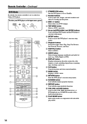
..., total time, and so on a DVD changer. button Selects discs on . To select your DVD player as the input source, press: RECEIVER 6 DVD or 5 MULTI CH 1 2 3 4 5 6 7 8 9 J STANDBY/ON REMOTE MODE RECEIVER DVD TAPE/AMP INPUT SELECTOR M D/CDR 1 2 3 VCR/DVR CBL/SAT C D DOCK 4 5 6 TV AUX MULTI CH DVD 7 8 9... Cancels functions and clears entered numbers. Remote Controller-Continued DVD Mode By default, the remote controller is set to control an Onkyo DVD player. C DISC +/- Q PLAY MODE button Selects play modes on a VCR/DVD recorder with selectable play modes. 14
..., total time, and so on a DVD changer. button Selects discs on . To select your DVD player as the input source, press: RECEIVER 6 DVD or 5 MULTI CH 1 2 3 4 5 6 7 8 9 J STANDBY/ON REMOTE MODE RECEIVER DVD TAPE/AMP INPUT SELECTOR M D/CDR 1 2 3 VCR/DVR CBL/SAT C D DOCK 4 5 6 TV AUX MULTI CH DVD 7 8 9... Cancels functions and clears entered numbers. Remote Controller-Continued DVD Mode By default, the remote controller is set to control an Onkyo DVD player. C DISC +/- Q PLAY MODE button Selects play modes on a VCR/DVD recorder with selectable play modes. 14

Owner Manual
Page 15
... I MENU button Used to an RI Dock. M PLAY MODE button Used to an RI Dock. F Playback buttons From left to control an Onkyo CD player. H CLR button Cancels functions and clears entered numbers on an HDDcompatible component connected to select play modes. Remote Controller-Continued CD/MD.../SAT * If you're using an MD, CDR, or an RI Dock, you must change the Input Display (see page 39). 1 2 3 4 5 6 7 STANDBY/ON REMOTE MODE RECEIVER DVD TAPE/AMP INPUT SELECTOR M D/CDR 1 2 3 VCR/DVR CBL/SAT C D DOCK 4 5 6 TV AUX MULTI CH DVD 7 8 9 VCR TAPE TUNER 10 11 +10 0 ...
... I MENU button Used to an RI Dock. M PLAY MODE button Used to an RI Dock. F Playback buttons From left to control an Onkyo CD player. H CLR button Cancels functions and clears entered numbers on an HDDcompatible component connected to select play modes. Remote Controller-Continued CD/MD.../SAT * If you're using an MD, CDR, or an RI Dock, you must change the Input Display (see page 39). 1 2 3 4 5 6 7 STANDBY/ON REMOTE MODE RECEIVER DVD TAPE/AMP INPUT SELECTOR M D/CDR 1 2 3 VCR/DVR CBL/SAT C D DOCK 4 5 6 TV AUX MULTI CH DVD 7 8 9 VCR TAPE TUNER 10 11 +10 0 ...
Owner Manual
Page 16
... • Expired batteries should be pressed continuously, thereby draining the batteries. • The remote controller may not work reliably if the AV receiver is installed close to bright light, such as direct sunlight or inverter-type fluorescent lights. Notes: • If the remote ...controller doesn't work if there's an obstacle between it toward the AV receiver's remote control sensor, as possible to prevent damage from leakage or corrosion. Aiming the Remote Controller When using the remote controller, point...
... • Expired batteries should be pressed continuously, thereby draining the batteries. • The remote controller may not work reliably if the AV receiver is installed close to bright light, such as direct sunlight or inverter-type fluorescent lights. Notes: • If the remote ...controller doesn't work if there's an obstacle between it toward the AV receiver's remote control sensor, as possible to prevent damage from leakage or corrosion. Aiming the Remote Controller When using the remote controller, point...

Owner Manual
Page 17
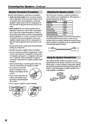
... feet (60-100 cm) above ear level. No matter how many speakers you have. You can enjoy Dolby Pro Logic IIx and Onkyo's own DSP surround listening modes. They should be positioned facing the listener at one surround back speaker, connect it to provide a solid ...wall length Surround left ✓✓✓✓ Surround right ✓✓✓✓ Surround back* ✓ * If you're using the AV receiver, you should connect seven speakers and a powered subwoofer. tion them inward slightly so as shown. In gen- The following table shows which channels ...
... feet (60-100 cm) above ear level. No matter how many speakers you have. You can enjoy Dolby Pro Logic IIx and Onkyo's own DSP surround listening modes. They should be positioned facing the listener at one surround back speaker, connect it to provide a solid ...wall length Surround left ✓✓✓✓ Surround right ✓✓✓✓ Surround back* ✓ * If you're using the AV receiver, you should connect seven speakers and a powered subwoofer. tion them inward slightly so as shown. In gen- The following table shows which channels ...
Owner Manual
Page 18
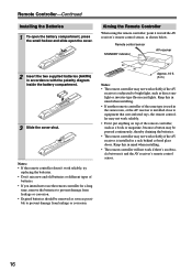
.... • Read the instructions supplied with your speakers. • Pay close attention to speaker wiring polarity. Attaching the Speaker Labels The AV receiver's positive (+) speaker terminals are color-coded for a long period of time, the built-in accordance with the above table. If you ...more than 6 ohms, be sure to set the minimum speaker impedance to "4 ohms" (see page 35). Doing so may damage the AV receiver. • Don't connect a speaker to tighten and loosen the speaker terminals. Connecting Your Speakers-Continued Speaker Connection Precautions Read the following before...
.... • Read the instructions supplied with your speakers. • Pay close attention to speaker wiring polarity. Attaching the Speaker Labels The AV receiver's positive (+) speaker terminals are color-coded for a long period of time, the built-in accordance with the above table. If you ...more than 6 ohms, be sure to set the minimum speaker impedance to "4 ohms" (see page 35). Doing so may damage the AV receiver. • Don't connect a speaker to tighten and loosen the speaker terminals. Connecting Your Speakers-Continued Speaker Connection Precautions Read the following before...
Owner Manual
Page 19
... Surround back right speaker Surround back left speaker Surround right speaker Surround left (L) SURROUND BACK SPEAKERS terminals. Connecting a Powered Subwoofer Using a suitable cable, connect the AV receiver's SUBWOOFER PRE OUT to the left speaker 19
... Surround back right speaker Surround back left speaker Surround right speaker Surround left (L) SURROUND BACK SPEAKERS terminals. Connecting a Powered Subwoofer Using a suitable cable, connect the AV receiver's SUBWOOFER PRE OUT to the left speaker 19

Owner Manual
Page 20
... attached securely and that you cannot achieve good reception with the supplied indoor FM antenna, try using thumbtacks. Push Insert wire Release Once your AV receiver is for use , you cannot achieve good reception with a commercially available outdoor AM antenna (see page 21). 20 If you 'll need...push terminals, as shown. 2 Connect both wires of the AM antenna to use only. 1 Attach the FM antenna, as possible from your AV receiver is for use , you must connect the antenna to achieve the best possible reception. Caution: Be careful that the push terminals are not polarity...
... attached securely and that you cannot achieve good reception with the supplied indoor FM antenna, try using thumbtacks. Push Insert wire Release Once your AV receiver is for use , you cannot achieve good reception with a commercially available outdoor AM antenna (see page 21). 20 If you 'll need...push terminals, as shown. 2 Connect both wires of the AM antenna to use only. 1 Attach the FM antenna, as possible from your AV receiver is for use , you must connect the antenna to achieve the best possible reception. Caution: Be careful that the push terminals are not polarity...
Owner Manual
Page 21
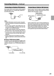
...-Continued Connecting an Outdoor FM Antenna If you cannot achieve good reception with local regulations to prevent electrical shock hazards. TV/FM antenna splitter To AV receiver To TV (or VCR) 21 Outdoor antenna AM loop antenna Insulated antenna cable Notes: • Outdoor FM antennas work best when installed horizontally outside , but...
...-Continued Connecting an Outdoor FM Antenna If you cannot achieve good reception with local regulations to prevent electrical shock hazards. TV/FM antenna splitter To AV receiver To TV (or VCR) 21 Outdoor antenna AM loop antenna Insulated antenna cable Notes: • Outdoor FM antennas work best when installed horizontally outside , but...
Owner Manual
Page 22
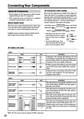
Optical Digital Jacks The AV receiver's optical digital jacks have shutter-type covers that open when an optical plug is the same as for optical. Push plugs in all AV connections. Jack OPTICAL COAXIAL L R Description This offers the best sound quality and allows you 've completed and double-checked all ...video is commonly used instead of a multichannel cable. Several standard analog audio cables can be used on virtually all the way. Note: The AV receiver does not support SCART connections. 22 Use red plugs to enjoy Dolby Digital and DTS. Connecting Your Components About...
Optical Digital Jacks The AV receiver's optical digital jacks have shutter-type covers that open when an optical plug is the same as for optical. Push plugs in all AV connections. Jack OPTICAL COAXIAL L R Description This offers the best sound quality and allows you 've completed and double-checked all ...video is commonly used instead of a multichannel cable. Several standard analog audio cables can be used on virtually all the way. Note: The AV receiver does not support SCART connections. 22 Use red plugs to enjoy Dolby Digital and DTS. Connecting Your Components About...


