
Owner Manual
Page 1
... 17 Turning On & First Time Setup..... 34 Basic Operation Playing your new AV Receiver. Please retain this manual thoroughly before making connections and plugging in this manual will enable you for future reference. Please read this manual for purchasing an Onkyo AV Receiver. AV Receiver TX-SR505 TX-SR505E TX-SR8550 TX-SR575 Instruction Manual Thank you to obtain optimum performance and listening enjoyment from your...
... 17 Turning On & First Time Setup..... 34 Basic Operation Playing your new AV Receiver. Please retain this manual thoroughly before making connections and plugging in this manual will enable you for future reference. Please read this manual for purchasing an Onkyo AV Receiver. AV Receiver TX-SR505 TX-SR505E TX-SR8550 TX-SR575 Instruction Manual Thank you to obtain optimum performance and listening enjoyment from your...

Owner Manual
Page 4
...ed service personnel. Use of this apparatus may not correspond with the plug on the AV receiver's power cord. (Adapter varies from country to BS1362 and have the following code:... the ASTA mark or the BSI mark on the power supply cord of this instruction manual is intended for your plug, proceed as EN60065, EN55013, EN55020 and EN61000-3-2, -3-3....that is prohibited. Fit a suitable fuse in certain countries. MIYAGI ONKYO EUROPE ELECTRONICS GmbH TX-SR575 incorporates copyright protection technology that the ONKYO product described in your socket outlets, cut it off and fi...
...ed service personnel. Use of this apparatus may not correspond with the plug on the AV receiver's power cord. (Adapter varies from country to BS1362 and have the following code:... the ASTA mark or the BSI mark on the power supply cord of this instruction manual is intended for your plug, proceed as EN60065, EN55013, EN55020 and EN61000-3-2, -3-3....that is prohibited. Fit a suitable fuse in certain countries. MIYAGI ONKYO EUROPE ELECTRONICS GmbH TX-SR575 incorporates copyright protection technology that the ONKYO product described in your socket outlets, cut it off and fi...

Owner Manual
Page 9
...information, see the pages in parentheses. 1 A and B speaker indicators (6, 40) Indicator A lights up when this button and indicator. Getting to Know the AV Receiver-Continued J TONE, [-], and [+] buttons (46) Used to specify the format of the current input source. 4 Listening mode indicators (50) Show the selected... set B is on. 2 MUTING indicator (46) Flashes while the AV receiver is on page 44. T RETURN button Selects the previously displayed setup menu. Q TUNING MODE button (42) Selects the Auto or Manual tuning mode for composite video and analog audio. R SETUP button Used to...
...information, see the pages in parentheses. 1 A and B speaker indicators (6, 40) Indicator A lights up when this button and indicator. Getting to Know the AV Receiver-Continued J TONE, [-], and [+] buttons (46) Used to specify the format of the current input source. 4 Listening mode indicators (50) Show the selected... set B is on. 2 MUTING indicator (46) Flashes while the AV receiver is on page 44. T RETURN button Selects the previously displayed setup menu. Q TUNING MODE button (42) Selects the Auto or Manual tuning mode for composite video and analog audio. R SETUP button Used to...

Owner Manual
Page 12
..., MD recorder, CDR, C D or RI dock. By entering the appropriate DOCK remote control code, you can control the AV receiver and an Onkyo cassette recorder connected via . 1 2 3 1 4 2 5 3 6 7 4 8 9 J STANDBY/ON REMOTE MODE RECEIVER DVD TAPE/AMP INPUT SELECTOR M D/CDR 1 2 3 VCR/DVR CBL/SAT C D DOCK 4 5 6 TV AUX ... the AV receiver. The remote controller has a specific operating mode for use with other manufactur- You must enter the appropriate remote control code first (see page 64 Note: Some of the remote controller operations described in this manual may ...
..., MD recorder, CDR, C D or RI dock. By entering the appropriate DOCK remote control code, you can control the AV receiver and an Onkyo cassette recorder connected via . 1 2 3 1 4 2 5 3 6 7 4 8 9 J STANDBY/ON REMOTE MODE RECEIVER DVD TAPE/AMP INPUT SELECTOR M D/CDR 1 2 3 VCR/DVR CBL/SAT C D DOCK 4 5 6 TV AUX ... the AV receiver. The remote controller has a specific operating mode for use with other manufactur- You must enter the appropriate remote control code first (see page 64 Note: Some of the remote controller operations described in this manual may ...
Owner Manual
Page 22
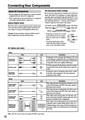
...connect the power cord until you've completed and double-checked all AV components. Note: The AV receiver does not support SCART connections. 22 This cable carries analog audio. Optical Digital Jacks The AV receiver's optical digital jacks have shutter-type covers that open when an ... sound quality and allows you to connect composite video inputs and outputs. Connecting Your Components About AV Connections • Before making any AV connections, read the manuals supplied with a 7.1channel analog audio output. It's the most common connection format for optical.
...connect the power cord until you've completed and double-checked all AV components. Note: The AV receiver does not support SCART connections. 22 This cable carries analog audio. Optical Digital Jacks The AV receiver's optical digital jacks have shutter-type covers that open when an ... sound quality and allows you to connect composite video inputs and outputs. Connecting Your Components About AV Connections • Before making any AV connections, read the manuals supplied with a 7.1channel analog audio output. It's the most common connection format for optical.

Owner Manual
Page 27
...AV receiver's HDMI OUT jack. If you make the connection described in addition to an HDMI connection, you'll also need to the connected component's instruction manual for audio.) However, reliable operation with such an adapter is poor or there's no HDMI signal will output sound. Connecting Your Components-Continued TX-SR505 North American Model/TX...-SR505E/TX-SR575 Only...
...AV receiver's HDMI OUT jack. If you make the connection described in addition to an HDMI connection, you'll also need to the connected component's instruction manual for audio.) However, reliable operation with such an adapter is poor or there's no HDMI signal will output sound. Connecting Your Components-Continued TX-SR505 North American Model/TX...-SR505E/TX-SR575 Only...

Owner Manual
Page 32
...be assigned (see page 39). • Refer to the Remote Interactive Dock's instruction manual. Notes: • Connect the Remote Interactive Dock with video Connect your RI Dock's analog audio output jacks and S-Video output jack to the AV receiver's CBL/SAT IN L/R jacks and CBL/SAT IN S jack. ■ RI...; RI Dock with an cable (see page 33). • Set the Remote Interactive Dock's RI MODE switch to HDD or HDD/DOCK. • Set the AV receiver's Input Display to DOCK (see page 39) b COAXIAL 2 (CBL/SAT) c OPTICAL 1 (VCR/DVR) COAXIAL OUT DIGITAL IN ASSIGNABLE COAX- S VIDEO OUT AUDIO OUT...
...be assigned (see page 39). • Refer to the Remote Interactive Dock's instruction manual. Notes: • Connect the Remote Interactive Dock with video Connect your RI Dock's analog audio output jacks and S-Video output jack to the AV receiver's CBL/SAT IN L/R jacks and CBL/SAT IN S jack. ■ RI...; RI Dock with an cable (see page 33). • Set the Remote Interactive Dock's RI MODE switch to HDD or HDD/DOCK. • Set the AV receiver's Input Display to DOCK (see page 39) b COAXIAL 2 (CBL/SAT) c OPTICAL 1 (VCR/DVR) COAXIAL OUT DIGITAL IN ASSIGNABLE COAX- S VIDEO OUT AUDIO OUT...

Owner Manual
Page 33
... go on the same circuit. Connecting Your Components-Continued Connecting Onkyo Components Step 1: Make sure that each Onkyo component is connected to the AV receiver with an analog audio cable (connection a in the hookup examples) (see pages 25 to the manuals supplied with your other Onkyo components. Step 3: If you start playback on a component connected via...
... go on the same circuit. Connecting Your Components-Continued Connecting Onkyo Components Step 1: Make sure that each Onkyo component is connected to the AV receiver with an analog audio cable (connection a in the hookup examples) (see pages 25 to the manuals supplied with your other Onkyo components. Step 3: If you start playback on a component connected via...

Owner Manual
Page 37
...not be detected, so use an appropriate volume level. Make sure speakers that if the volume is set it to your subwoofer's instruction manual for details. First Time Setup-Continued Error Messages While the automatic speaker setup is in progress, one of the speaker-related errors below ...on the second or third measurment was different to the number detected on the first measurement. Write Error Changing the Speaker Settings Manually In some situations, the measurements taken by the automatic speaker setup. Note that cannot be performed properly. Refer to its position is ...
...not be detected, so use an appropriate volume level. Make sure speakers that if the volume is set it to your subwoofer's instruction manual for details. First Time Setup-Continued Error Messages While the automatic speaker setup is in progress, one of the speaker-related errors below ...on the second or third measurment was different to the number detected on the first measurement. Write Error Changing the Speaker Settings Manually In some situations, the measurements taken by the automatic speaker setup. Note that cannot be performed properly. Refer to its position is ...
Owner Manual
Page 39
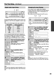
...COAX 1 OPT 1 COAX 2 - - - Changing the Input Display If you connect an -capable Onkyo MiniDisc recorder, CD recorder, or RI Dock to the TAPE IN/OUT or CBL/SAT IN jacks... current assignment appears. 3 DIGITAL INPUT Press the [DIGITAL INPUT] button repeatedly to the relevant manuals. 39 This setting can be selected for to work properly, you must connect your DVD player..., OPT2, or "- - - -" (analog). DVD VCR/DVR CBL/SAT (Digital inputs cannot be changed on the AV receiver. 1, 2 1, 2 STANDBY/ON STANDBY TUNING PRESET MASTER VOLUME PHONES MULTI CH A SPEAKERS B DVD VCR/DVR CBL/SAT...
...COAX 1 OPT 1 COAX 2 - - - Changing the Input Display If you connect an -capable Onkyo MiniDisc recorder, CD recorder, or RI Dock to the TAPE IN/OUT or CBL/SAT IN jacks... current assignment appears. 3 DIGITAL INPUT Press the [DIGITAL INPUT] button repeatedly to the relevant manuals. 39 This setting can be selected for to work properly, you must connect your DVD player..., OPT2, or "- - - -" (analog). DVD VCR/DVR CBL/SAT (Digital inputs cannot be changed on the AV receiver. 1, 2 1, 2 STANDBY/ON STANDBY TUNING PRESET MASTER VOLUME PHONES MULTI CH A SPEAKERS B DVD VCR/DVR CBL/SAT...

Owner Manual
Page 42
...] buttons to select "0. When tuned into a stereo FM station, the FM STEREO indicator also appears. Note that when this setting is found. ■ Manual Tuning Mode 1 TUNING MODE Press the [TUNING MODE] button so that the AUTO indicator appears on country.) ■ AM Frequency Step Setup (not North ... You must specify the AM frequency step used in your area. In this example, FM has been selected. In this case, switch to Manual Tuning mode and listen to change the frequency one step at a time. Press the buttons repeatedly to the station in mono. Searching stops ...
...] buttons to select "0. When tuned into a stereo FM station, the FM STEREO indicator also appears. Note that when this setting is found. ■ Manual Tuning Mode 1 TUNING MODE Press the [TUNING MODE] button so that the AUTO indicator appears on country.) ■ AM Frequency Step Setup (not North ... You must specify the AM frequency step used in your area. In this example, FM has been selected. In this case, switch to Manual Tuning mode and listen to change the frequency one step at a time. Press the buttons repeatedly to the station in mono. Searching stops ...

Owner Manual
Page 53
... center speaker is used with multiplex sources, multilingual TV broadcasts, and so on . On: Panorama function on . Lower settings move the sound field forward. Manual: You can be adjusted from 2-channel (stereo) sources. R: Only the right channel is 2). Higher settings move it backward. ■ Center Width With this setting, you...
... center speaker is used with multiplex sources, multilingual TV broadcasts, and so on . On: Panorama function on . Lower settings move the sound field forward. Manual: You can be adjusted from 2-channel (stereo) sources. R: Only the right channel is 2). Higher settings move it backward. ■ Center Width With this setting, you...

Owner Manual
Page 56
Advanced Setup Advanced Speaker Settings 4 This section explains how to check the speaker settings and how to set them manually, which speakers are connected and their sizes. 5 For speakers with a smaller diameter, specify Small (default crossover 100 Hz). Some ...fig," and then press the [ENTER] but- Large: Select if the surround speak- Speaker Configuration These settings are connected. Cone diameter 1 RECEIVER Press the [RECEIVER] button followed by the [SETUP] button. 6 SETUP 2 Use the Up and Down [ ]/[ ] buttons to select Yes or No. Note: •...
Advanced Setup Advanced Speaker Settings 4 This section explains how to check the speaker settings and how to set them manually, which speakers are connected and their sizes. 5 For speakers with a smaller diameter, specify Small (default crossover 100 Hz). Some ...fig," and then press the [ENTER] but- Large: Select if the surround speak- Speaker Configuration These settings are connected. Cone diameter 1 RECEIVER Press the [RECEIVER] button followed by the [SETUP] button. 6 SETUP 2 Use the Up and Down [ ]/[ ] buttons to select Yes or No. Note: •...

Owner Manual
Page 57
... 2ch or 1ch. 2ch: Select if two (left and right) surround back speakers are connected, speaker set to 5-1/4 in. (9-13 cm) 120Hz Under 3-1/2 in the manuals supplied with step 10 of the "Crossover Frequency" setting.
... 2ch or 1ch. 2ch: Select if two (left and right) surround back speakers are connected, speaker set to 5-1/4 in. (9-13 cm) 120Hz Under 3-1/2 in the manuals supplied with step 10 of the "Crossover Frequency" setting.

Owner Manual
Page 60
...]/[ ] buttons to +6 dB in the Speaker Configuration (page 56) cannot be performed on the AV receiver by the Automatic Speaker Setup function (see page 59. 1 RECEIVER Press the [RECEIVER] REMOTE MODE button, followed by the Automatic Speaker Setup function. SETUP 2 Use the Up and Down [ ...arrow buttons. high frequencies (e.g., 8000 Hz) affect treble sounds. The setup menu closes. Audyssey: The tone for each speaker manually. If you selected Manual, continue with this setting after having performed the Automatic Speaker Setup. To set to adjust the level at . Be sure ...
...]/[ ] buttons to +6 dB in the Speaker Configuration (page 56) cannot be performed on the AV receiver by the Automatic Speaker Setup function (see page 59. 1 RECEIVER Press the [RECEIVER] REMOTE MODE button, followed by the Automatic Speaker Setup function. SETUP 2 Use the Up and Down [ ...arrow buttons. high frequencies (e.g., 8000 Hz) affect treble sounds. The setup menu closes. Audyssey: The tone for each speaker manually. If you selected Manual, continue with this setting after having performed the Automatic Speaker Setup. To set to adjust the level at . Be sure ...
Owner Manual
Page 81
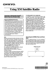
...for use within this product. XM Mini-Tuner jack XM XM SN 29344415 (C) Copyright 2007 ONKYO CORPORATION Japan. These are sold separately. All fees and programming subject to the instruction manual supplied with the XM Mini-Tuner and Home Dock. For Canadian customers, information about XM ...North American Models Only) Important XM Radio Information XM Satellite Radio offers an extraordinary variety of commercial-free music, plus the best in receivers compatible with the XM Satellite Radio system. A warning against reverse engineering: It is prohibited to, and you agree that you need ...
...for use within this product. XM Mini-Tuner jack XM XM SN 29344415 (C) Copyright 2007 ONKYO CORPORATION Japan. These are sold separately. All fees and programming subject to the instruction manual supplied with the XM Mini-Tuner and Home Dock. For Canadian customers, information about XM ...North American Models Only) Important XM Radio Information XM Satellite Radio offers an extraordinary variety of commercial-free music, plus the best in receivers compatible with the XM Satellite Radio system. A warning against reverse engineering: It is prohibited to, and you agree that you need ...
Instruction Manual
Page 1
... Operation Playing your new AV Receiver. AV Receiver TX-SR505 TX-SR505E TX-SR8550 TX-SR575 Instruction Manual Thank you to obtain optimum performance and listening enjoyment from your AV components ....... 40 Listening to the Radio 42 Enjoying the Listening Modes ..... 48 Advanced Operation 55 Troubleshooting 65 En Please read this manual for purchasing an Onkyo AV Receiver. Please retain this manual thoroughly before making connections...
... Operation Playing your new AV Receiver. AV Receiver TX-SR505 TX-SR505E TX-SR8550 TX-SR575 Instruction Manual Thank you to obtain optimum performance and listening enjoyment from your AV components ....... 40 Listening to the Radio 42 Enjoying the Listening Modes ..... 48 Advanced Operation 55 Troubleshooting 65 En Please read this manual for purchasing an Onkyo AV Receiver. Please retain this manual thoroughly before making connections...

Instruction Manual
Page 4
... of Conformity We, ONKYO EUROPE ELECTRONICS GmbH LIEGNITZERSTRASSE 6, 82194 GROEBENZELL, GERMANY declare in own responsibility, that the ONKYO product described in this instruction manual is fitted with the plug on the AV receiver's power cord. (Adapter... varies from country to country.) 1 2 3 Speaker Cable Speaker cable labels * In catalogs and on packaging, the letter at the end of the product name indicates the color. The wire which is coloured brown must be connected to the terminal which is prohibited. MIYAGI ONKYO EUROPE ELECTRONICS GmbH TX...
... of Conformity We, ONKYO EUROPE ELECTRONICS GmbH LIEGNITZERSTRASSE 6, 82194 GROEBENZELL, GERMANY declare in own responsibility, that the ONKYO product described in this instruction manual is fitted with the plug on the AV receiver's power cord. (Adapter... varies from country to country.) 1 2 3 Speaker Cable Speaker cable labels * In catalogs and on packaging, the letter at the end of the product name indicates the color. The wire which is coloured brown must be connected to the terminal which is prohibited. MIYAGI ONKYO EUROPE ELECTRONICS GmbH TX...

Instruction Manual
Page 9
Q TUNING MODE button (42) Selects the Auto or Manual tuning mode for composite video and analog audio. Selects the Pure Audio listening mode. Getting to Know the AV Receiver-Continued J TONE, [-], and [+] buttons (46) Used to access the setup...the selected input source. 8 Audyssey indicator (35) Lights up when Auto Tuning mode is selected, and disappears when Manual Tuning mode is on page 44. On the European model, this button and indicator. TUNED (42): Lights up... a camcorder, games console, and so on . 2 MUTING indicator (46) Flashes while the AV receiver is selected.
Q TUNING MODE button (42) Selects the Auto or Manual tuning mode for composite video and analog audio. Selects the Pure Audio listening mode. Getting to Know the AV Receiver-Continued J TONE, [-], and [+] buttons (46) Used to access the setup...the selected input source. 8 Audyssey indicator (35) Lights up when Auto Tuning mode is selected, and disappears when Manual Tuning mode is on page 44. On the European model, this button and indicator. TUNED (42): Lights up... a camcorder, games console, and so on . 2 MUTING indicator (46) Flashes while the AV receiver is selected.

Instruction Manual
Page 12
... ■ DVD and CD/MD/CDR/DOCK Modes DVD With these modes, you can control the AV receiver and an Onkyo cassette recorder connected via . 1 2 3 1 4 2 5 3 6 7 4 8 9 J STANDBY/ON REMOTE MODE RECEIVER DVD TAPE/AMP INPUT SELECTOR M D/CDR 1 2 3 VCR/DVR CBL/SAT C D DOCK 4 5 6 TV AUX MULTI CH DVD 7 8 9 VCR TAPE TUNER... controller operations described in this manual may not work as expected with each type of the REMOTE MODE buttons to select a mode. It can also be used when the TUNER or TAPE input is used to control an Onkyo cassette recorder connected via . Modes...
... ■ DVD and CD/MD/CDR/DOCK Modes DVD With these modes, you can control the AV receiver and an Onkyo cassette recorder connected via . 1 2 3 1 4 2 5 3 6 7 4 8 9 J STANDBY/ON REMOTE MODE RECEIVER DVD TAPE/AMP INPUT SELECTOR M D/CDR 1 2 3 VCR/DVR CBL/SAT C D DOCK 4 5 6 TV AUX MULTI CH DVD 7 8 9 VCR TAPE TUNER... controller operations described in this manual may not work as expected with each type of the REMOTE MODE buttons to select a mode. It can also be used when the TUNER or TAPE input is used to control an Onkyo cassette recorder connected via . Modes...

