
Owner Manual
Page 1
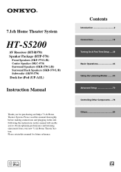
... instructions in this manual thoroughly before making connections and plugging in the unit. Please retain this manual for purchasing an Onkyo 7.1ch Home Theater System. 7.1ch Home Theater System HT-S5200 AV Receiver (HT-R570) Speaker Package (HTP-570) Front Speakers (SKF-570 L/R) Center Speaker (SKC-570) Surround Speakers (SKR-570 L/R) Surround Back Speakers (SKB...
... instructions in this manual thoroughly before making connections and plugging in the unit. Please retain this manual for purchasing an Onkyo 7.1ch Home Theater System. 7.1ch Home Theater System HT-S5200 AV Receiver (HT-R570) Speaker Package (HTP-570) Front Speakers (SKF-570 L/R) Center Speaker (SKC-570) Surround Speakers (SKR-570 L/R) Surround Back Speakers (SKB...
Owner Manual
Page 3
... or plastic items on this Unit with a clean cloth. However, there is encouraged to try to radio or television reception, which the receiver is not userserviceable. For Canadian Models NOTE: THIS CLASS B DIGITAL APPARATUS COMPLIES WITH CANADIAN ICES-003. AC Fuse-The AC fuse inside .... • Increase the separation between the equipment and receiver. • Connect the equipment into an outlet on , so be exposed to use . For stubborn stains, use only, recording copyrighted material is used in your Onkyo dealer. 8. The power cord plug is illegal without the permission of mild ...
... or plastic items on this Unit with a clean cloth. However, there is encouraged to try to radio or television reception, which the receiver is not userserviceable. For Canadian Models NOTE: THIS CLASS B DIGITAL APPARATUS COMPLIES WITH CANADIAN ICES-003. AC Fuse-The AC fuse inside .... • Increase the separation between the equipment and receiver. • Connect the equipment into an outlet on , so be exposed to use . For stubborn stains, use only, recording copyrighted material is used in your Onkyo dealer. 8. The power cord plug is illegal without the permission of mild ...
Owner Manual
Page 4
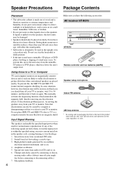
... over the speakers, the drive units may still be an issue, in which neutralizes the magnetic field, thereby removing any of the following accessories: AV receiver HT-R570 HT-R570 Remote controller and two batteries (AA/R6) Speaker setup microphone Indoor FM antenna AM loop antenna * In catalogs and on . 4. In some situations, however, discoloration...
... over the speakers, the drive units may still be an issue, in which neutralizes the magnetic field, thereby removing any of the following accessories: AV receiver HT-R570 HT-R570 Remote controller and two batteries (AA/R6) Speaker setup microphone Indoor FM antenna AM loop antenna * In catalogs and on . 4. In some situations, however, discoloration...

Owner Manual
Page 6
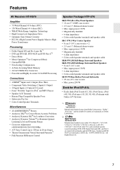
Using Two Sets of Speakers Speaker Sets A and B You can be used in your source component with the AV receiver: speaker set A and speaker set B. Speaker set B can use two sets of speakers with an analog connection. Connect your main listening room for up to 7.1-...
Using Two Sets of Speakers Speaker Sets A and B You can be used in your source component with the AV receiver: speaker set A and speaker set B. Speaker set B can use two sets of speakers with an analog connection. Connect your main listening room for up to 7.1-...
Owner Manual
Page 7
...A1L • Easily links iPod Touch (1G, 2G), iPod Classic, iPod (4G, 5G), iPod nano (1G, 2G, 3G, 4G), iPod mini with Onkyo A/V Systems *1 Manufactured under U.S. and worldwide patents issued & pending. DTS, DTS Digital Surround, ES, and Neo:6 are registered trademarks and the DTS logos...; Max. Patent #'s: 5,451,942; 5,956,674; 5,974,380; 5,978,762; 6,226,616; 6,487,535; 7,003,467; 7,212,872 & other U.S. Features AV Receiver HT-R570 Amplifier • 75 Watts/Channel @ 8 ohms (FTC) • 130 Watts/Channel @ 6 ohms (IEC) • WRAT-Wide Range Amplifier Technology • High-Current Low...
...A1L • Easily links iPod Touch (1G, 2G), iPod Classic, iPod (4G, 5G), iPod nano (1G, 2G, 3G, 4G), iPod mini with Onkyo A/V Systems *1 Manufactured under U.S. and worldwide patents issued & pending. DTS, DTS Digital Surround, ES, and Neo:6 are registered trademarks and the DTS logos...; Max. Patent #'s: 5,451,942; 5,956,674; 5,974,380; 5,978,762; 6,226,616; 6,487,535; 7,003,467; 7,212,872 & other U.S. Features AV Receiver HT-R570 Amplifier • 75 Watts/Channel @ 8 ohms (FTC) • 130 Watts/Channel @ 6 ohms (IEC) • WRAT-Wide Range Amplifier Technology • High-Current Low...
Owner Manual
Page 8
...Onkyo Corporation. *4 HDMI, the HDMI logo and High Definition Multimedia Interface are trademarks or registered trademarks of HDMI Licensing, LLC. *5 SIRIUS, XM and all related marks and logos are trademarks of Apple Inc., registered in the U.S. and its subsidiaries. U.S. All rights reserved. SIRIUS subscription sold separately) to receive... in Alaska or Hawaii. *6 Manufactured under license from Audyssey Laboratories. Service not available in receivers compatible with the SIRIUS Satellite Radio System. and other marks and logos are trademarks of Audyssey Laboratories. *7 Theater-...
...Onkyo Corporation. *4 HDMI, the HDMI logo and High Definition Multimedia Interface are trademarks or registered trademarks of HDMI Licensing, LLC. *5 SIRIUS, XM and all related marks and logos are trademarks of Apple Inc., registered in the U.S. and its subsidiaries. U.S. All rights reserved. SIRIUS subscription sold separately) to receive... in Alaska or Hawaii. *6 Manufactured under license from Audyssey Laboratories. Service not available in receivers compatible with the SIRIUS Satellite Radio System. and other marks and logos are trademarks of Audyssey Laboratories. *7 Theater-...
Owner Manual
Page 9
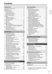
...UP-A1L 5 Using Two Sets of Speakers 6 Speaker Sets A and B 6 Features 7 AV Receiver HT-R570 7 Speaker Package HTP-570 7 Dock for iPod UP-A1L 7 Front & Rear Panels 10 Front...Subwoofer 21 Connecting Antenna 22 About AV Connections 24 Connecting Audio and Video Signals to the AV receiver 25 Which Connections Should I Use 25 Connecting Components with HDMI 26 Making HDMI Connections 27 ...Connecting the Supplied UP-A1L Dock 36 Connecting Onkyo V Components 37 Connecting the Power Cord 37 Turning On & First Time Setup Turning On the AV receiver 38 Turning On and Standby 38 First Time...
...UP-A1L 5 Using Two Sets of Speakers 6 Speaker Sets A and B 6 Features 7 AV Receiver HT-R570 7 Speaker Package HTP-570 7 Dock for iPod UP-A1L 7 Front & Rear Panels 10 Front...Subwoofer 21 Connecting Antenna 22 About AV Connections 24 Connecting Audio and Video Signals to the AV receiver 25 Which Connections Should I Use 25 Connecting Components with HDMI 26 Making HDMI Connections 27 ...Connecting the Supplied UP-A1L Dock 36 Connecting Onkyo V Components 37 Connecting the Power Cord 37 Turning On & First Time Setup Turning On the AV receiver 38 Turning On and Standby 38 First Time...
Owner Manual
Page 10
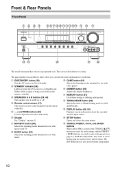
...(64) Selects the listening modes intended for use with music. They are used to select and set items. The [ENTER] button is being received from the remote controller. L MEMORY button (51) Used when storing or deleting radio presets. P TUNING, PRESET, Arrow, and ENTER buttons ...AM or FM is on it. D SPEAKERS A & B buttons (18, 44) Turn speaker sets A and B on page 11. E Remote control sensor (17) This sensor receives control signals from the remote controller. N DISPLAY button (46, 50) Displays various information about the currently selected input source. I J K L M NO P Q R ST U...
...(64) Selects the listening modes intended for use with music. They are used to select and set items. The [ENTER] button is being received from the remote controller. L MEMORY button (51) Used when storing or deleting radio presets. P TUNING, PRESET, Arrow, and ENTER buttons ...AM or FM is on it. D SPEAKERS A & B buttons (18, 44) Turn speaker sets A and B on page 11. E Remote control sensor (17) This sensor receives control signals from the remote controller. N DISPLAY button (46, 50) Displays various information about the currently selected input source. I J K L M NO P Q R ST U...
Owner Manual
Page 11
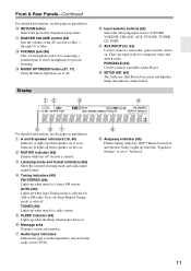
... as the audio source: PCM. There are input jacks for AM or FM radio. R MASTER VOLUME control (44) Sets the volume of the AV receiver to connect a portable Audio Player. PORTABLE (33): Used to Min, 1 through 79, or Max. G Message area Displays various information. Lights up when...Select the following input sources: DVD/BD, VCR/DVR, CBL/SAT, AUX, TV/TAPE, TUNER, CD, PORT. C MUTING indicator (45) Flashes while the AV receiver is selected. V AUX INPUT (33, 63) Used to "Audyssey". 11 AUTO (49): Lights up when tuned to a stereo FM station. T MUSIC OPTIMIZER button...
... as the audio source: PCM. There are input jacks for AM or FM radio. R MASTER VOLUME control (44) Sets the volume of the AV receiver to connect a portable Audio Player. PORTABLE (33): Used to Min, 1 through 79, or Max. G Message area Displays various information. Lights up when...Select the following input sources: DVD/BD, VCR/DVR, CBL/SAT, AUX, TV/TAPE, TUNER, CD, PORT. C MUTING indicator (45) Flashes while the AV receiver is selected. V AUX INPUT (33, 63) Used to "Audyssey". 11 AUTO (49): Lights up when tuned to a stereo FM station. T MUSIC OPTIMIZER button...
Owner Manual
Page 12
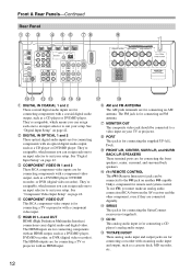
... be connected to a video input on page 42. They're assignable, which means you can be connected to the V jack on another V-capable Onkyo component for connecting components with an HDMI output, such as a CD player or DVD/BD player. The HDMI inputs are connected digitally. M CD ... input. G AM and FM ANTENNA The AM push terminals are for connecting the supplied UP-A1L Dock. I PORT This jack is for connecting the SiriusConnect receiver (not supplied). L SIRIUS This jack is for connecting a TV or projector with a component video output, such as a DVD/BD player, DVD/BD ...
... be connected to a video input on page 42. They're assignable, which means you can be connected to the V jack on another V-capable Onkyo component for connecting components with an HDMI output, such as a CD player or DVD/BD player. The HDMI inputs are connected digitally. M CD ... input. G AM and FM ANTENNA The AM push terminals are for connecting the supplied UP-A1L Dock. I PORT This jack is for connecting the SiriusConnect receiver (not supplied). L SIRIUS This jack is for connecting a TV or projector with a component video output, such as a DVD/BD player, DVD/BD ...
Owner Manual
Page 13
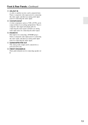
... the video signal, and there are analog audio input jacks for connecting the audio signal. Front & Rear Panels-Continued O CBL/SAT IN A cable or satellite receiver can be connected here for recording and playback. There is composite video input jacks for connecting the video signal, and there are for connecting speaker...
... the video signal, and there are analog audio input jacks for connecting the audio signal. Front & Rear Panels-Continued O CBL/SAT IN A cable or satellite receiver can be connected here for recording and playback. There is composite video input jacks for connecting the video signal, and there are for connecting speaker...

Owner Manual
Page 14
... a certain level. Note: The Auto Standby function turns the subwoofer on when an input signal is used to the subwoofer pre out on the AV receiver (page 72). Speaker Package Subwoofer (SKW-570) For detailed information, see the pages in parentheses. ■ Front B ■ Rear B STANDBY/ON... in Standby mode. If the Auto Standby function does not work reliably, try slightly increasing or decreasing the subwoofer output level on the AV receiver with supplied RCA cable. When there's no input signal for a while, the SKW-570 automatically enters Standby mode. To AC outlet CD 14...
... a certain level. Note: The Auto Standby function turns the subwoofer on when an input signal is used to the subwoofer pre out on the AV receiver (page 72). Speaker Package Subwoofer (SKW-570) For detailed information, see the pages in parentheses. ■ Front B ■ Rear B STANDBY/ON... in Standby mode. If the Auto Standby function does not work reliably, try slightly increasing or decreasing the subwoofer output level on the AV receiver with supplied RCA cable. When there's no input signal for a while, the SKW-570 automatically enters Standby mode. To AC outlet CD 14...
Owner Manual
Page 16
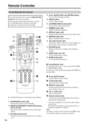
... sources. H DIMMER button (45) Adjusts the display brightness. J MUTING button (45) Mutes or unmutes the AV receiver. K VOL [R]/[X] button (44) Adjusts the volume of the AV receiver regardless of the currently selected remote controller mode. M AUDIO button (47, 76) Used to On or Standby. N... 16 E Arrow [R]/[X]/[F]/[S] and ENTER buttons Used to select the listening modes. You can also be controlled in Receiver mode (see the pages in parentheses. Note: An Onkyo cassette recorder connected via V can also use the remote controller to the previous display when changing settings. L ...
... sources. H DIMMER button (45) Adjusts the display brightness. J MUTING button (45) Mutes or unmutes the AV receiver. K VOL [R]/[X] button (44) Adjusts the volume of the AV receiver regardless of the currently selected remote controller mode. M AUDIO button (47, 76) Used to On or Standby. N... 16 E Arrow [R]/[X]/[F]/[S] and ENTER buttons Used to select the listening modes. You can also be controlled in Receiver mode (see the pages in parentheses. Note: An Onkyo cassette recorder connected via V can also use the remote controller to the previous display when changing settings. L ...

Owner Manual
Page 17
... corrosion. • Expired batteries should be pressed continuously, thereby draining the batteries. • The remote controller may not work reliably if the AV receiver is subjected to prevent damage from leakage or corrosion. 30° 30° Approx. 16 ft. (5 m) Notes: • The remote controller... may not work reliably if the AV receiver is installed in mind when installing. • The remote controller will not work reliably, try replacing the batteries. • Don't mix new and...
... corrosion. • Expired batteries should be pressed continuously, thereby draining the batteries. • The remote controller may not work reliably if the AV receiver is subjected to prevent damage from leakage or corrosion. 30° 30° Approx. 16 ft. (5 m) Notes: • The remote controller... may not work reliably if the AV receiver is installed in mind when installing. • The remote controller will not work reliably, try replacing the batteries. • Don't mix new and...
Owner Manual
Page 18
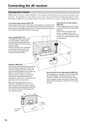
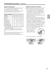
... improve sound localization behind , about 2-3 feet (60-100 cm) above ear level. Connecting the AV receiver Enjoying Home Theater Thanks to the AV receiver's superb capabilities, you can enjoy Dolby Pro Logic IIx, DTS Neo:6, or Onkyo's original DSP listening modes. They should be obtained by placing your subwoofer will depend on top...
... improve sound localization behind , about 2-3 feet (60-100 cm) above ear level. Connecting the AV receiver Enjoying Home Theater Thanks to the AV receiver's superb capabilities, you can enjoy Dolby Pro Logic IIx, DTS Neo:6, or Onkyo's original DSP listening modes. They should be obtained by placing your subwoofer will depend on top...
Owner Manual
Page 19
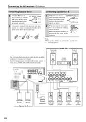
... use based on the number of speakers you 're using only one cable to the SURR BACK L terminals. Doing so may damage the AV receiver. • Don't connect more than one surround back speaker, connect it to each speaker terminal. Doing so may damage the AV... receiver. • Don't connect a speaker to speaker wiring polarity. Connect positive (+) terminals to only positive (+) terminals, and negative (-) terminals to short the positive and negative ...
... use based on the number of speakers you 're using only one cable to the SURR BACK L terminals. Doing so may damage the AV receiver. • Don't connect more than one surround back speaker, connect it to each speaker terminal. Doing so may damage the AV... receiver. • Don't connect a speaker to speaker wiring polarity. Connect positive (+) terminals to only positive (+) terminals, and negative (-) terminals to short the positive and negative ...
Owner Manual
Page 20
...-12mm) mm) of insulation from the ends of the speaker cables. (Supplied speaker cables are gripping the bare wires, not the insulation. Connecting the AV receiver-Continued Connecting Speaker Set A 1 Strip 1/2"-5/8" (12-15 1/2"-5/8"(12-15mm) mm) of insulation from the ends of the speaker cables, and twist the bare wires tightly...
...-12mm) mm) of insulation from the ends of the speaker cables. (Supplied speaker cables are gripping the bare wires, not the insulation. Connecting the AV receiver-Continued Connecting Speaker Set A 1 Strip 1/2"-5/8" (12-15 1/2"-5/8"(12-15mm) mm) of insulation from the ends of the speaker cables, and twist the bare wires tightly...
Owner Manual
Page 21
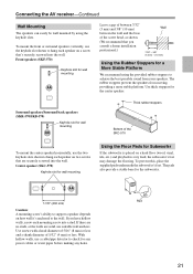
... screwed into a stud. Center speaker (SKC-570) Keyhole slot for wall mounting Using the Floor Pads for the center speaker. Pad 21 Connecting the AV receiver-Continued Wall Mounting The speakers can easily be wall mounted by using the provided rubber stoppers to achieve the best possible sound from moving, providing...
... screwed into a stud. Center speaker (SKC-570) Keyhole slot for wall mounting Using the Floor Pads for the center speaker. Pad 21 Connecting the AV receiver-Continued Wall Mounting The speakers can easily be wall mounted by using the provided rubber stoppers to achieve the best possible sound from moving, providing...
Owner Manual
Page 22
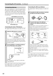
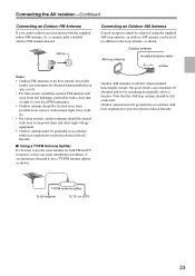
... section explains how to connect the supplied indoor FM antenna and AM loop antenna, and how to achieve the best possible reception. Once your AV receiver is for use only. 1 Attach the FM antenna, as shown. (The antenna's wires are not polarity sensitive, so they can be connected either way around... Antenna The supplied indoor FM antenna is ready for indoor use the tuner. Insert the plug fully into the base, as possible from your AV receiver is for use, you must connect the antenna to fix the FM antenna into an FM radio station and adjust the position of the AM...
... section explains how to connect the supplied indoor FM antenna and AM loop antenna, and how to achieve the best possible reception. Once your AV receiver is for use only. 1 Attach the FM antenna, as shown. (The antenna's wires are not polarity sensitive, so they can be connected either way around... Antenna The supplied indoor FM antenna is ready for indoor use the tuner. Insert the plug fully into the base, as possible from your AV receiver is for use, you must connect the antenna to fix the FM antenna into an FM radio station and adjust the position of the AM...
Owner Manual
Page 23
...-voltage equipment. • Outdoor antenna must be grounded in addition to prevent electrical shock hazards. TV/FM antenna splitter To AV receiver To TV (or VCR) 23 Connecting the AV receiver-Continued Connecting an Outdoor FM Antenna If you cannot achieve good reception with local regulations to the loop antenna, as shown...
...-voltage equipment. • Outdoor antenna must be grounded in addition to prevent electrical shock hazards. TV/FM antenna splitter To AV receiver To TV (or VCR) 23 Connecting the AV receiver-Continued Connecting an Outdoor FM Antenna If you cannot achieve good reception with local regulations to the loop antenna, as shown...


