
Owner Manual
Page 1
Please read this manual thoroughly before making connections and plugging in this manual for purchasing an Onkyo 7.1ch Home Theater System. Following the instructions in the unit. Please retain this manual will enable you for future reference. Contents...your AV components ....... 36 Listening to obtain optimum performance and listening enjoyment from your new 7.1ch Home Theater System. 7.1ch Home Theater System HT-S790 AV Receiver (HT-R540) Front Speakers (SKF-540F) Center Speaker (SKC-540C) Surround Speakers (SKM-540S) Surround Back Speakers (SKB-540) Powered Subwoofer (SKW-540...
Please read this manual thoroughly before making connections and plugging in this manual for purchasing an Onkyo 7.1ch Home Theater System. Following the instructions in the unit. Please retain this manual will enable you for future reference. Contents...your AV components ....... 36 Listening to obtain optimum performance and listening enjoyment from your new 7.1ch Home Theater System. 7.1ch Home Theater System HT-S790 AV Receiver (HT-R540) Front Speakers (SKF-540F) Center Speaker (SKC-540C) Surround Speakers (SKM-540S) Surround Back Speakers (SKB-540) Powered Subwoofer (SKW-540...
Owner Manual
Page 3
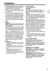
... turn it was when you do not use this unit for User CAUTION: The user changes or modifications not expressly approved by your Onkyo dealer. 3. Never Touch this unit, use . For U.S. For Canadian Models NOTE: THIS CLASS B DIGITAL APPARATUS COMPLIES WITH CANADIAN ICES-003. ... Dry the unit immediately afterwards with Wet Hands-Never handle this equipment does cause harmful interference to radio or television reception, which the receiver is no guarantee that the voltage in a particular installation. Power WARNING BEFORE PLUGGING IN THE UNIT FOR THE FIRST TIME, READ THE...
... turn it was when you do not use this unit for User CAUTION: The user changes or modifications not expressly approved by your Onkyo dealer. 3. Never Touch this unit, use . For U.S. For Canadian Models NOTE: THIS CLASS B DIGITAL APPARATUS COMPLIES WITH CANADIAN ICES-003. ... Dry the unit immediately afterwards with Wet Hands-Never handle this equipment does cause harmful interference to radio or television reception, which the receiver is no guarantee that the voltage in a particular installation. Power WARNING BEFORE PLUGGING IN THE UNIT FOR THE FIRST TIME, READ THE...
Owner Manual
Page 5
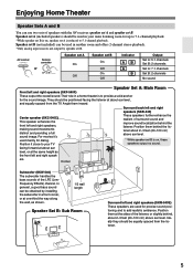
Enjoying Home Theater Speaker Sets A and B You can use two sets of the LFE (LowFrequency Effects) channel. AV receiver SPEAKERS A B Remote controller or Speaker set A On Off Speaker set B is reduced to add realistic ambience. For movies it close to provide a ...solid anchor for dialog. Subwoofer (SKW-540) The subwoofer handles the bass sounds of speakers with the AV receiver: speaker set A and speaker set B. Ideally they should be obtained by speaker set A is on , speaker set B. Angle them behind , about 2-3 feet ...
Enjoying Home Theater Speaker Sets A and B You can use two sets of the LFE (LowFrequency Effects) channel. AV receiver SPEAKERS A B Remote controller or Speaker set A On Off Speaker set B is reduced to add realistic ambience. For movies it close to provide a ...solid anchor for dialog. Subwoofer (SKW-540) The subwoofer handles the bass sounds of speakers with the AV receiver: speaker set A and speaker set B. Ideally they should be obtained by speaker set A is on , speaker set B. Angle them behind , about 2-3 feet ...
Owner Manual
Page 6
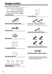
...fications and operation are the same regardless of the product name indicates the color. Package Contents Make sure you have the following items: AV receiver (HT-R540) Remote controller & two batteries (AA/R6) Indoor FM antenna AM loop antenna Front speakers (SKF-540F) Center speaker (SKC-540C) Surround and Surround back speakers...
...fications and operation are the same regardless of the product name indicates the color. Package Contents Make sure you have the following items: AV receiver (HT-R540) Remote controller & two batteries (AA/R6) Indoor FM antenna AM loop antenna Front speakers (SKF-540F) Center speaker (SKC-540C) Surround and Surround back speakers...
Owner Manual
Page 8
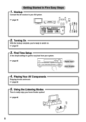
Hookup Connect the AV receiver to get the very best from your AV system. ☞ page 19 XM DIGITAL IN COA XIAL OPTICAL 1 COMPONENT VIDEO VIDEO 2 IN VIDEO 1 IN DVD ...
Hookup Connect the AV receiver to get the very best from your AV system. ☞ page 19 XM DIGITAL IN COA XIAL OPTICAL 1 COMPONENT VIDEO VIDEO 2 IN VIDEO 1 IN DVD ...
Owner Manual
Page 9
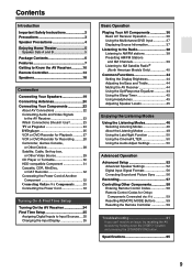
..., MiniDisc, or DAT Recorder 32 Connecting the Power Cord of Another Component 32 Connecting Onkyo Components..........33 Connecting the Power Cord 33 Turning On & First Time Setup Turning On the AV Receiver 34 First Time Setup 35 Assigning Digital Inputs to Input Sources ....35 Changing the Input... (North American Models Only 40 Common Functions 44 Setting the Display Brightness 44 Adjusting the Bass and Treble 44 Muting the AV Receiver 44 Using the OptiResponse Equalizer 44 Using the Sleep Timer 45 Using Headphones 45 Adjusting Speaker Levels 45 Enjoying the Listening Modes Using...
..., MiniDisc, or DAT Recorder 32 Connecting the Power Cord of Another Component 32 Connecting Onkyo Components..........33 Connecting the Power Cord 33 Turning On & First Time Setup Turning On the AV Receiver 34 First Time Setup 35 Assigning Digital Inputs to Input Sources ....35 Changing the Input... (North American Models Only 40 Common Functions 44 Setting the Display Brightness 44 Adjusting the Bass and Treble 44 Muting the AV Receiver 44 Using the OptiResponse Equalizer 44 Using the Sleep Timer 45 Using Headphones 45 Adjusting Speaker Levels 45 Enjoying the Listening Modes Using...
Owner Manual
Page 10
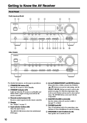
...selected, the TUNING [ ] [ ] buttons are used for private listening. H PHONES jack (45) This 1/4-inch phone jack is for connecting a standard pair of the AV receiver to MIN, 1 through 79, or MAX. The [MULTI CH] button selects the multichannel DVD input. Getting to Know the AV... Receiver Front Panel North American Model 12 3 45 6 7 STANDBY/ON STANDBY PHONES TUNING PRESET MULTI CH DVD VIDEO 1 VIDEO 2 VIDEO 3 TAPE TUNER C D ENTER RETURN SETUP SPEAKERS A...
...selected, the TUNING [ ] [ ] buttons are used for private listening. H PHONES jack (45) This 1/4-inch phone jack is for connecting a standard pair of the AV receiver to MIN, 1 through 79, or MAX. The [MULTI CH] button selects the multichannel DVD input. Getting to Know the AV... Receiver Front Panel North American Model 12 3 45 6 7 STANDBY/ON STANDBY PHONES TUNING PRESET MULTI CH DVD VIDEO 1 VIDEO 2 VIDEO 3 TAPE TUNER C D ENTER RETURN SETUP SPEAKERS A...

Owner Manual
Page 11
... input source. 11 Q TUNING MODE button (38) Selects the Auto or Manual tuning mode for composite video and analog audio. Getting to Know the AV Receiver-Continued J TONE, [-], and [+] buttons (44) Used to access the setup menus. T VIDEO 3 INPUT (28, 57) Used to specify the format of digital audio signals. 4 ...button (35, 56) Used to assign the digital inputs and to connect a camcorder, games console, and so on . 2 MUTING indicator (44) Flashes while the AV receiver is selected. MEMORY (39): Lights up when Auto Tuning is selected, and disappears when Manual Tuning mode is selected.
... input source. 11 Q TUNING MODE button (38) Selects the Auto or Manual tuning mode for composite video and analog audio. Getting to Know the AV Receiver-Continued J TONE, [-], and [+] buttons (44) Used to access the setup menus. T VIDEO 3 INPUT (28, 57) Used to specify the format of digital audio signals. 4 ...button (35, 56) Used to assign the digital inputs and to connect a camcorder, games console, and so on . 2 MUTING indicator (44) Flashes while the AV receiver is selected. MEMORY (39): Lights up when Auto Tuning is selected, and disappears when Manual Tuning mode is selected.
Owner Manual
Page 12
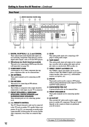
..., sold separately (see page 40). The VIDEO 2 inputs can be used to supply power to another -capable Onkyo com- The type of outlet depends on your AV receiver. G FRONT SPEAKERS A, SURROUND SPEAKERS, CENTER SPEAKER, and SURROUND BACK SPEAKERS These terminal posts are for connecting an... SURR BACK R VIDEO 2 VIDEO 1 SUB WOOFER DVD SURROUND SPEAKERS FRONT SPEAKERS A L CENTER SPEAKER R PRE OUT SUB WOOFER FRONT SPEAKERS B L R AV RECEIVER AC OUTLET AC 120V 60Hz SWITCHED TOTAL 120W 1A MAX. 8 9J K L MN O A DIGITAL IN OPTICAL 1, 2, 3, and COAXIAL These optical and coaxial...
..., sold separately (see page 40). The VIDEO 2 inputs can be used to supply power to another -capable Onkyo com- The type of outlet depends on your AV receiver. G FRONT SPEAKERS A, SURROUND SPEAKERS, CENTER SPEAKER, and SURROUND BACK SPEAKERS These terminal posts are for connecting an... SURR BACK R VIDEO 2 VIDEO 1 SUB WOOFER DVD SURROUND SPEAKERS FRONT SPEAKERS A L CENTER SPEAKER R PRE OUT SUB WOOFER FRONT SPEAKERS B L R AV RECEIVER AC OUTLET AC 120V 60Hz SWITCHED TOTAL 120W 1A MAX. 8 9J K L MN O A DIGITAL IN OPTICAL 1, 2, 3, and COAXIAL These optical and coaxial...

Owner Manual
Page 13
... subjected to equipment that uses infrared rays, the remote controller may not work reliably if the AV receiver is installed in the same room, or the AV receiver is installed close to bright light, such as shown below. Keep this in accordance with the polarity diagram inside... the battery compartment. 3 Slide the cover shut. Remote control sensor STANDBY indicator AV receiver 2 Insert the two supplied batteries (AA/R6) in mind when installing. • The remote controller will not work reliably. • Don...
... subjected to equipment that uses infrared rays, the remote controller may not work reliably if the AV receiver is installed in the same room, or the AV receiver is installed close to bright light, such as shown below. Keep this in accordance with the polarity diagram inside... the battery compartment. 3 Slide the cover shut. Remote control sensor STANDBY indicator AV receiver 2 Insert the two supplied batteries (AA/R6) in mind when installing. • The remote controller will not work reliably. • Don...
Owner Manual
Page 14
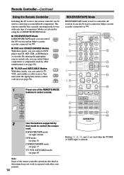
... ■ DVD and CD/MD/CDR/HDD Modes With these modes, you can control Onkyo components or components made by other components. 14 RECEIVER/TAPE Mode RECEIVER/TAPE mode is used when the TUNER or TAPE input is selected. Modes are used to... SAT 2 Use the buttons supported by using the six REMOTE MODE buttons. ■ RECEIVER/TAPE Mode In RECEIVER/TAPE mode, you can control RECEIVER the AV receiver and an Onkyo cassette TAPE recorder connected via . 1 2 3 1 4 2 5 36 7 4 8 9 J K ON/STANDBY REMOTE MODE RECEIVER DVD TAPE INPUT SELECTOR 1 2 3 V1 V2 V3 M D/CDR C D HDD ...
... ■ DVD and CD/MD/CDR/HDD Modes With these modes, you can control Onkyo components or components made by other components. 14 RECEIVER/TAPE Mode RECEIVER/TAPE mode is used when the TUNER or TAPE input is selected. Modes are used to... SAT 2 Use the buttons supported by using the six REMOTE MODE buttons. ■ RECEIVER/TAPE Mode In RECEIVER/TAPE mode, you can control RECEIVER the AV receiver and an Onkyo cassette TAPE recorder connected via . 1 2 3 1 4 2 5 36 7 4 8 9 J K ON/STANDBY REMOTE MODE RECEIVER DVD TAPE INPUT SELECTOR 1 2 3 V1 V2 V3 M D/CDR C D HDD ...
Owner Manual
Page 15
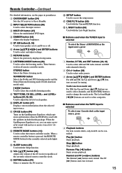
...fast forward. 15 When a remote controller button is used when the TUNER input is on the OptiResponse Equalizer, which optimizes performance when the HT-R540 is pressed, the REMOTE MODE button for tuning. Q CINE FLTR button (50) Used with the Sleep function. H LISTENING MODE buttons (... you can be controlled. M SLEEP button (45) Used with the CinemaFILTER function. O MUTING button (44) Mutes or unmutes the AV receiver. C MULTI CH button (37) Selects the multichannel DVD input. These buttons work in parentheses. Remote Controller-Continued For detailed information, see the...
...fast forward. 15 When a remote controller button is used when the TUNER input is on the OptiResponse Equalizer, which optimizes performance when the HT-R540 is pressed, the REMOTE MODE button for tuning. Q CINE FLTR button (50) Used with the Sleep function. H LISTENING MODE buttons (... you can be controlled. M SLEEP button (45) Used with the CinemaFILTER function. O MUTING button (44) Mutes or unmutes the AV receiver. C MULTI CH button (37) Selects the multichannel DVD input. These buttons work in parentheses. Remote Controller-Continued For detailed information, see the...
Owner Manual
Page 16
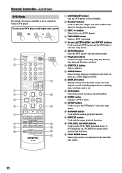
... to right: Pause, Play, Stop, Fast Reverse, Fast Forward, Previous, and Next. E Arrow and ENTER buttons Used to control an Onkyo DVD player. J DISPLAY button Displays information about the current disc, title, chapter, or track, including elapsed time, remaining time, total time... STEREO SURROUND AUDIO SUBTITLE RANDOM REPEAT TEST TONE CH SEL LEVEL- To select your DVD player as the input source, press: RECEIVER 6 DVD or 5 MULTI CH 1 2 3 4 5 6 7 8 9 J ON/STANDBY REMOTE MODE RECEIVER DVD TAPE INPUT SELECTOR 1 2 3 V1 V2 V3 M D/CDR C D HDD 4 5 6 TV MULTI CH DVD 7 8 9 ...
... to right: Pause, Play, Stop, Fast Reverse, Fast Forward, Previous, and Next. E Arrow and ENTER buttons Used to control an Onkyo DVD player. J DISPLAY button Displays information about the current disc, title, chapter, or track, including elapsed time, remaining time, total time... STEREO SURROUND AUDIO SUBTITLE RANDOM REPEAT TEST TONE CH SEL LEVEL- To select your DVD player as the input source, press: RECEIVER 6 DVD or 5 MULTI CH 1 2 3 4 5 6 7 8 9 J ON/STANDBY REMOTE MODE RECEIVER DVD TAPE INPUT SELECTOR 1 2 3 V1 V2 V3 M D/CDR C D HDD 4 5 6 TV MULTI CH DVD 7 8 9 ...
Owner Manual
Page 17
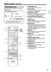
... recorder. L PLAY MODE button Used to navigate menus on an HDD-compatible component. B Number buttons Used to control an Onkyo CD player. To select the input source, press: RECEIVER 9 CD player C D 7 MD or CD recorder TAPE 7 or 2 Next generation HDDcompatible component TAPE V2 * If ...you're using an MD, CDR, or HDD component, you must change the Input Display (see page 35). 1 2 3 4 E F ON/STANDBY REMOTE MODE RECEIVER DVD TAPE INPUT SELECTOR 1 2 3 V1 V2 V3 M D/CDR C D HDD 4 5 6 TV MULTI CH DVD 7 8 9 VCR TAPE TUNER 10 11 +10 0 C D ...
... recorder. L PLAY MODE button Used to navigate menus on an HDD-compatible component. B Number buttons Used to control an Onkyo CD player. To select the input source, press: RECEIVER 9 CD player C D 7 MD or CD recorder TAPE 7 or 2 Next generation HDDcompatible component TAPE V2 * If ...you're using an MD, CDR, or HDD component, you must change the Input Display (see page 35). 1 2 3 4 E F ON/STANDBY REMOTE MODE RECEIVER DVD TAPE INPUT SELECTOR 1 2 3 V1 V2 V3 M D/CDR C D HDD 4 5 6 TV MULTI CH DVD 7 8 9 VCR TAPE TUNER 10 11 +10 0 C D ...
Owner Manual
Page 18
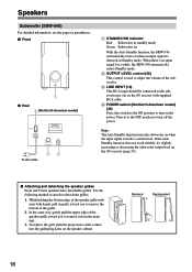
... subwoofer output level on when an input signal is used to adjust the volume of the speaker grille toward you to turn on the AV receiver with supplied RCA cable. Press it to the OFF position to remove it gently toward you to the subwoofer pre out on the power. Removal... control (36) This control is detected in standby mode Green: Subwoofer on With the Auto Standby function, the SKW-540 automatically turns on the AV receiver (page 53). ■ Attaching and detaching the speaker grilles Front and Center speakers have detachable grilles.
... subwoofer output level on when an input signal is used to adjust the volume of the speaker grille toward you to turn on the AV receiver with supplied RCA cable. Press it to the OFF position to remove it gently toward you to the subwoofer pre out on the power. Removal... control (36) This control is detected in standby mode Green: Subwoofer on With the Auto Standby function, the SKW-540 automatically turns on the AV receiver (page 53). ■ Attaching and detaching the speaker grilles Front and Center speakers have detachable grilles.
Owner Manual
Page 19
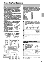
...be out of 8 ohms or higher. Brown Gray Tan Surround Surround Surround Surround Back Right Back Left Right Left Connecting Speaker Set A The AV receiver's positive (+) speaker terminals and speaker's positive (+) terminals are color-coded for a long period of time, the built-in protection circuit may ...Read the following before making any connections. • Pay close attention to short the positive and negative wires. Doing so may damage the AV receiver. • Don't connect one cable to each cable to only negative (-) terminals. If you get them the wrong way around, the ...
...be out of 8 ohms or higher. Brown Gray Tan Surround Surround Surround Surround Back Right Back Left Right Left Connecting Speaker Set A The AV receiver's positive (+) speaker terminals and speaker's positive (+) terminals are color-coded for a long period of time, the built-in protection circuit may ...Read the following before making any connections. • Pay close attention to short the positive and negative wires. Doing so may damage the AV receiver. • Don't connect one cable to each cable to only negative (-) terminals. If you get them the wrong way around, the ...
Owner Manual
Page 20
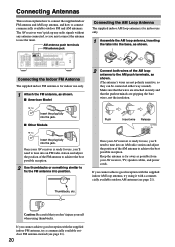
...signals without any antenna connected, so you cannot achieve good reception with the supplied indoor AM loop antenna, try using thumbtacks. Once your AV receiver is ready for indoor use only. 1 Assemble the AM loop antenna, inserting the tabs into an AM radio station and adjust the position of...into position. Keep the antenna as far away as shown. (The antenna's wires are gripping the bare wires, not the insulation. Once your AV receiver, TV, speaker cables, and power cords. Caution: Be careful that the push terminals are not polarity sensitive, so they can be connected either ...
...signals without any antenna connected, so you cannot achieve good reception with the supplied indoor AM loop antenna, try using thumbtacks. Once your AV receiver is ready for indoor use only. 1 Assemble the AM loop antenna, inserting the tabs into an AM radio station and adjust the position of...into position. Keep the antenna as far away as shown. (The antenna's wires are gripping the bare wires, not the insulation. Once your AV receiver, TV, speaker cables, and power cords. Caution: Be careful that the push terminals are not polarity sensitive, so they can be connected either ...
Owner Manual
Page 21
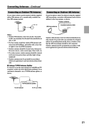
... loop antenna, as shown. Outdoor antenna must be grounded in addition to use a TV/FM antenna splitter, as shown. TV/FM antenna splitter To AV receiver To TV (or VCR) 21 Connecting Antennas-Continued Connecting an Outdoor FM Antenna If you cannot achieve good reception with local regulations to prevent electrical...
... loop antenna, as shown. Outdoor antenna must be grounded in addition to use a TV/FM antenna splitter, as shown. TV/FM antenna splitter To AV receiver To TV (or VCR) 21 Connecting Antennas-Continued Connecting an Outdoor FM Antenna If you cannot achieve good reception with local regulations to prevent electrical...
Owner Manual
Page 22
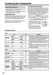
Optical Digital Jacks The AV receiver's optical digital jacks have shutter-type covers that open when an optical plug is commonly used to connect left-channel audio inputs and outputs (typically ...
Optical Digital Jacks The AV receiver's optical digital jacks have shutter-type covers that open when an optical plug is commonly used to connect left-channel audio inputs and outputs (typically ...
Owner Manual
Page 23
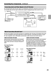
...between formats. OUT Input Cassette recorder, etc. Analog 23 Video Signal Flow Chart DVD player, etc. Output Optical Coaxial IN AV Receiver Optical Coaxial Analog Multichannel Analog Multichannel TV, projector, etc. Speakers (see page 19 for compatibility with a wide range of AV ... want to the analog CD IN. Video Connection Formats Audio Connection Formats When choosing a connection format, bear in mind that the AV receiver doesn't convert between formats, so only outputs of the same format as a guide. For example, audio signals connected to an OPTICAL ...
...between formats. OUT Input Cassette recorder, etc. Analog 23 Video Signal Flow Chart DVD player, etc. Output Optical Coaxial IN AV Receiver Optical Coaxial Analog Multichannel Analog Multichannel TV, projector, etc. Speakers (see page 19 for compatibility with a wide range of AV ... want to the analog CD IN. Video Connection Formats Audio Connection Formats When choosing a connection format, bear in mind that the AV receiver doesn't convert between formats, so only outputs of the same format as a guide. For example, audio signals connected to an OPTICAL ...


