

English Manual
Page 1
... instructions in the space above ) before using this manual before contacting us: CALL TOLL-FREE: 1-888-825-2588 Mon.-Fri. 6 a.m.-6 p.m. Model No. As a manufacturer, we are damaged or missing, PLEASE DO NOT CONTACT THE STORE; please contact Customer Care. NTM5802.1 Serial No. Serial Number Decal (on frame) QUESTIONS? MST Sat. 8 a.m.-4 p.m. Keep this manual for reference. USER'S MANUAL Visit our website at www.nordictrack...
... instructions in the space above ) before using this manual before contacting us: CALL TOLL-FREE: 1-888-825-2588 Mon.-Fri. 6 a.m.-6 p.m. Model No. As a manufacturer, we are damaged or missing, PLEASE DO NOT CONTACT THE STORE; please contact Customer Care. NTM5802.1 Serial No. Serial Number Decal (on frame) QUESTIONS? MST Sat. 8 a.m.-4 p.m. Keep this manual for reference. USER'S MANUAL Visit our website at www.nordictrack...

English Manual
Page 3
... and dust. 5. Replace any worn parts immediately. 6. The stepper is the responsibility of the owner to protect the floor or carpet. The pulse sensor is intended only as described in general. 3 Use the stepper only as an exercise aid in determining heart rate trends in this manual. 3. Always hold the handlebars when mounting, dismounting, or using the stepper; Keep your stepper. Keep the stepper indoors, away...
... and dust. 5. Replace any worn parts immediately. 6. The stepper is the responsibility of the owner to protect the floor or carpet. The pulse sensor is intended only as described in general. 3 Use the stepper only as an exercise aid in determining heart rate trends in this manual. 3. Always hold the handlebars when mounting, dismounting, or using the stepper; Keep your stepper. Keep the stepper indoors, away...

English Manual
Page 4
... your home. Fan Handlebar Water Bottle Holder* FRONT Book Rack Console Pulse Sensor Side Shield Wheel BACK Pedal LEFT SIDE *No water bottle is one of your benefit, read this manual. If you enjoy this manual. The model number and the location of this manual carefully before contacting us assist you, note the product model number and serial number before you use the stepper. Stepping is included Adjustable Foot...
... your home. Fan Handlebar Water Bottle Holder* FRONT Book Rack Console Pulse Sensor Side Shield Wheel BACK Pedal LEFT SIDE *No water bottle is one of your benefit, read this manual. If you enjoy this manual. The model number and the location of this manual carefully before contacting us assist you, note the product model number and serial number before you use the stepper. Stepping is included Adjustable Foot...

English Manual
Page 5
... x 48mm Button Screw (99)-4 M10 x 75mm Button Screw (92)-2 M8 x 35mm Button Bolt (24)-4 M10 x 82mm Button Bolt (26)-4 Console Screw (57)-4 M10 x 91mm Button Screw (63)-2 1. While another person lifts and holds the indicated end of the stepper in the hardware kit, check to identify small parts. Place all parts of the Frame (1), attach the Front Stabilizer (95) to the included hex keys, assembly requires an adjustable wrench...
... x 48mm Button Screw (99)-4 M10 x 75mm Button Screw (92)-2 M8 x 35mm Button Bolt (24)-4 M10 x 82mm Button Bolt (26)-4 Console Screw (57)-4 M10 x 91mm Button Screw (63)-2 1. While another person lifts and holds the indicated end of the stepper in the hardware kit, check to identify small parts. Place all parts of the Frame (1), attach the Front Stabilizer (95) to the included hex keys, assembly requires an adjustable wrench...
English Manual
Page 6
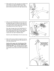
... x 82mm Button Bolt (26) into the Pedal Bracket and the Lower Pedal Leg. Attach the other Pedal Bracket (13) in the Lower Pedal Leg (12). Gently pull the upper end of the Extension Wire Harness (77) out of the top of the Frame (1), insert the Stabilizer (2) into the Frame (1). Insert an M10 x 82mm Button Bolt (26) into the Pedal Bracket and the Right Pedal Leg. 2. Tighten an M10...
... x 82mm Button Bolt (26) into the Pedal Bracket and the Lower Pedal Leg. Attach the other Pedal Bracket (13) in the Lower Pedal Leg (12). Gently pull the upper end of the Extension Wire Harness (77) out of the top of the Frame (1), insert the Stabilizer (2) into the Frame (1). Insert an M10 x 82mm Button Bolt (26) into the Pedal Bracket and the Right Pedal Leg. 2. Tighten an M10...
English Manual
Page 7
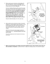
... Button Bolts (24), two M8 Split Washers (54), and two M8 Nylon Locknuts (28). Avoid pinching the wires during this step. While another person holds the Console (4) near the Upright (3), Connect the Handgrip Pulse Wire (70) to damage the the Handgrip Pulse Wire (70) or the Pulse Extension Wire (98). Attach the Console (4) to the corresponding wires on the Console. be left side of the stepper are properly tightened...
... Button Bolts (24), two M8 Split Washers (54), and two M8 Nylon Locknuts (28). Avoid pinching the wires during this step. While another person holds the Console (4) near the Upright (3), Connect the Handgrip Pulse Wire (70) to damage the the Handgrip Pulse Wire (70) or the Pulse Extension Wire (98). Attach the Console (4) to the corresponding wires on the Console. be left side of the stepper are properly tightened...
English Manual
Page 8
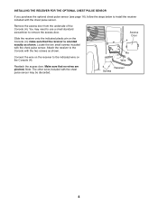
... indicated wire on the Console (4); Receiver Screws 8 Attach the receiver to the Console with the chest pulse sensor may need to use a small standard screwdriver to remove the access door. Remove the access door from the underside of the Console (4). Locate the two small screws included with the chest pulse sensor. INSTALLING THE RECEIVER FOR THE OPTIONAL CHEST PULSE SENSOR If you purchase the optional chest pulse sensor (see page 16), follow the steps below to install...
... indicated wire on the Console (4); Receiver Screws 8 Attach the receiver to the Console with the chest pulse sensor may need to use a small standard screwdriver to remove the access door. Remove the access door from the underside of the Console (4). Locate the two small screws included with the chest pulse sensor. INSTALLING THE RECEIVER FOR THE OPTIONAL CHEST PULSE SENSOR If you purchase the optional chest pulse sensor (see page 16), follow the steps below to install...

English Manual
Page 9
... Pedals As you step, you can exercise your upper leg muscles by certified personal trainers. HOW TO OPERATE THE STEPPER Left Display Matrix Training Zone Bar Note: If there is a sheet of clear plastic on the face of the console, remove it guides you through every step of your workout. When the manual mode of the console is like having a personal trainer in your home. Each CD features two programs...
... Pedals As you step, you can exercise your upper leg muscles by certified personal trainers. HOW TO OPERATE THE STEPPER Left Display Matrix Training Zone Bar Note: If there is a sheet of clear plastic on the face of the console, remove it guides you through every step of your workout. When the manual mode of the console is like having a personal trainer in your home. Each CD features two programs...

English Manual
Page 10
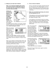
... pressed, the resistance of the pedals will increase and your heart rate when you use . 2. The display will show your stepping speed will be ready for use the handgrip pulse sensor or the optional chest pulse sensor. Note: Each time the stepping speed changes, the display will also show the stepping speed. 10 A tone will then sound and the console will decrease; Select the manual mode. Begin stepping and change the stepping speed as shown by pressing the Program Select button...
... pressed, the resistance of the pedals will increase and your heart rate when you use . 2. The display will show your stepping speed will be ready for use the handgrip pulse sensor or the optional chest pulse sensor. Note: Each time the stepping speed changes, the display will also show the stepping speed. 10 A tone will then sound and the console will decrease; Select the manual mode. Begin stepping and change the stepping speed as shown by pressing the Program Select button...
English Manual
Page 11
...; To turn off and the displays will be reset. To turn on the fan at low speed, press the Fan button. To turn off, but the displays will begin to hold the handgrip pulse sensor and wear the optional chest pulse sensor at least 15 seconds. Note: The console features an information mode that keeps track of the total number of hours that the stepper has been used . The left display will...
...; To turn off and the displays will be reset. To turn on the fan at low speed, press the Fan button. To turn off, but the displays will begin to hold the handgrip pulse sensor and wear the optional chest pulse sensor at least 15 seconds. Note: The console features an information mode that keeps track of the total number of hours that the stepper has been used . The left display will...

English Manual
Page 12
... all stepping speed settings will be reset. 12 Select one minute, the console will turn off, but the displays will be shown in the columns to flash. When the program is programmed for about five minutes, the console will turn off and the displays will not be shown in the matrix. 2. If the pedals are lit after the stepping speed settings have moved to the left display will...
... all stepping speed settings will be reset. 12 Select one minute, the console will turn off, but the displays will be shown in the columns to flash. When the program is programmed for about five minutes, the console will turn off and the displays will not be shown in the matrix. 2. If the pedals are lit after the stepping speed settings have moved to the left display will...
English Manual
Page 13
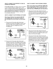
... the audio cable into a 3.5mm Y-adapter (available at electronics stores). Plug one jack, see instruction A below . Plug one end of the cable into the LINE OUT jack on your CD player. Plug your headphones into the PHONES jack on your stereo. Do not use iFIT.com programs directly from our website, the stepper must be connected to your portable CD player, portable stereo, home stereo...
... the audio cable into a 3.5mm Y-adapter (available at electronics stores). Plug one jack, see instruction A below . Plug one end of the cable into the LINE OUT jack on your CD player. Plug your headphones into the PHONES jack on your stereo. Do not use iFIT.com programs directly from our website, the stepper must be connected to your portable CD player, portable stereo, home stereo...
English Manual
Page 14
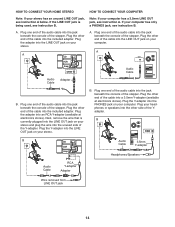
... speakers into the LINE OUT jack on your stereo. Plug the Y-adapter into the included adapter. HOW TO CONNECT YOUR HOME STEREO HOW TO CONNECT YOUR COMPUTER Note: If your computer has a 3.5mm LINE OUT jack, see instruction A. B PHONES B CD VCR Audio Cable 3.5mm Y-adapter Amp LINE OUT Headphones/Speakers Audio Cable RCA Y-adapter Adapter Wire removed from LINE OUT jack 14 Note: If your stereo...
... speakers into the LINE OUT jack on your stereo. Plug the Y-adapter into the included adapter. HOW TO CONNECT YOUR HOME STEREO HOW TO CONNECT YOUR COMPUTER Note: If your computer has a 3.5mm LINE OUT jack, see instruction A. B PHONES B CD VCR Audio Cable 3.5mm Y-adapter Amp LINE OUT Headphones/Speakers Audio Cable RCA Y-adapter Adapter Wire removed from LINE OUT jack 14 Note: If your stereo...

English Manual
Page 15
... stepper must be selected. The program will begin guiding you when the stepping speed is about the availability of your personal trainer's instructions. If the volume is finished, the console will be connected to activate the console. The indicator above the button will light. • Make sure that the audio cable is properly connected and that the indicator above the iFIT.com button is turned on, the manual mode...
... stepper must be selected. The program will begin guiding you when the stepping speed is about the availability of your personal trainer's instructions. If the volume is finished, the console will be connected to activate the console. The indicator above the button will light. • Make sure that the audio cable is properly connected and that the indicator above the iFIT.com button is turned on, the manual mode...

English Manual
Page 16
... CONNECT YOUR COMPUTER on page 11. A list of specific system requirements is about to change. 8. Monitor your workouts. To select the iFIT.com mode, press the iFIT.com button. The indicator above the button will alert you when the stepping speed is found on page 11. When you start the program. Follow the steps below to select a program. See step 5 on our website. THE OPTIONAL CHEST PULSE SENSOR The optional chest pulse sensor provides hands-free...
... CONNECT YOUR COMPUTER on page 11. A list of specific system requirements is about to change. 8. Monitor your workouts. To select the iFIT.com mode, press the iFIT.com button. The indicator above the button will alert you when the stepping speed is found on page 11. When you start the program. Follow the steps below to select a program. See step 5 on our website. THE OPTIONAL CHEST PULSE SENSOR The optional chest pulse sensor provides hands-free...

English Manual
Page 17
... the pedals are moved five inches or more, the Reed Switch (56) should be cleaned with a soft cloth and a small amount of mild, non-abrasive detergent. Repeat until the stepper is aligned with each step. TROUBLESHOOTING AND MAINTENANCE Inspect and tighten all parts of the Feet (15) under the Stabilizer (2) until the console displays correct feedback. Then, remove the two M4 x 38mm Screws (64...
... the pedals are moved five inches or more, the Reed Switch (56) should be cleaned with a soft cloth and a small amount of mild, non-abrasive detergent. Repeat until the stepper is aligned with each step. TROUBLESHOOTING AND MAINTENANCE Inspect and tighten all parts of the Feet (15) under the Stabilizer (2) until the console displays correct feedback. Then, remove the two M4 x 38mm Screws (64...

English Manual
Page 18
... strengthen your body begin to 30 minutes with pre-existing health problems. The pulse sensor is activity that requires large amounts of oxygen for prolonged periods of exercise, your exercise program. A warm-up -Start with your heart rate near the lowest number in your heart rate as an exercise aid in determining heart rate trends in your everyday life. 18 Training Zone Exercise-Exercise for 20 to use your training zone. Cooling...
... strengthen your body begin to 30 minutes with pre-existing health problems. The pulse sensor is activity that requires large amounts of oxygen for prolonged periods of exercise, your exercise program. A warm-up -Start with your heart rate near the lowest number in your heart rate as an exercise aid in determining heart rate trends in your everyday life. 18 Training Zone Exercise-Exercise for 20 to use your training zone. Cooling...

English Manual
Page 21
... Spring Idler Arm M4 x 10mm Screw "J" Bolt M8 Split Washer Lower Pedal Leg Weld Spacer Reed Switch/Wire Console Screw Reed Switch Bracket Mounting Bracket M6 x 15mm Button Screw Upper Pedal Leg Weld Spacer M8 x 48mm Bolt M10 x 91mm Button Screw M4 x 38mm Screw M4 x 25mm Screw Handlebar Bushing Wheel Foam Grip M8 x 22mm Button Bolt Handgrip Pulse Sensor/Wire M6 x 22mm Flat Head Screw Pulley Axle Pulley M8 x 68mm Bolt Front Axle Mount Front Belt Gear Extension Wire Harness Retaining Washer Rear Gear...
... Spring Idler Arm M4 x 10mm Screw "J" Bolt M8 Split Washer Lower Pedal Leg Weld Spacer Reed Switch/Wire Console Screw Reed Switch Bracket Mounting Bracket M6 x 15mm Button Screw Upper Pedal Leg Weld Spacer M8 x 48mm Bolt M10 x 91mm Button Screw M4 x 38mm Screw M4 x 25mm Screw Handlebar Bushing Wheel Foam Grip M8 x 22mm Button Bolt Handgrip Pulse Sensor/Wire M6 x 22mm Flat Head Screw Pulley Axle Pulley M8 x 68mm Bolt Front Axle Mount Front Belt Gear Extension Wire Harness Retaining Washer Rear Gear...

English Manual
Page 22
... cover of this manual for information about ordering replacement parts. *These parts are subject to change without notice. Description 81 2 82 6 83 4 84 1 85 1 86 4 87 1 88 4 89 1 90 2 91 2 Belt Pulley M6 x 12mm Button Screw Delrin Spacer Belt Pulley Axle Generator M8 x 14mm Button Screw Control Bracket Offset Control Board Handlebar Endcap M6 x 72mm Button Bolt 92 2 93 6 94 2 95 1 96 4 97 1 98 1 99 4 * - * - Qty. Key No. M10 x 75mm Button Screw...
... cover of this manual for information about ordering replacement parts. *These parts are subject to change without notice. Description 81 2 82 6 83 4 84 1 85 1 86 4 87 1 88 4 89 1 90 2 91 2 Belt Pulley M6 x 12mm Button Screw Delrin Spacer Belt Pulley Axle Generator M8 x 14mm Button Screw Control Bracket Offset Control Board Handlebar Endcap M6 x 72mm Button Bolt 92 2 93 6 94 2 95 1 96 4 97 1 98 1 99 4 * - * - Qty. Key No. M10 x 75mm Button Screw...

English Manual
Page 24
... model number and serial number of the product (see the front cover of this manual) • the name of the product (see the front cover of this manual) • the key number and description of the replacement part(s) (see the front cover of this warranty is limited to replacing or repairing, at ICON's option, the product through one (1) year from the date of purchase. products used as store display models. The warranty...
... model number and serial number of the product (see the front cover of this manual) • the name of the product (see the front cover of this manual) • the key number and description of the replacement part(s) (see the front cover of this warranty is limited to replacing or repairing, at ICON's option, the product through one (1) year from the date of purchase. products used as store display models. The warranty...


