

English Manual
Page 2
... release the press arms, butterfly arms, leg lever, lat bar, row bar, or ab strap while weights are on page 3. Always stand on a level surface. Table of Contents Important Precautions 2 Before You Begin 3 Assembly 4 Weight Resistance Chart 23 Cable Diagrams 24 Adjustment 26 Trouble-shooting and Maintenance 27 Ordering Replacement Parts Back...
... release the press arms, butterfly arms, leg lever, lat bar, row bar, or ab strap while weights are on page 3. Always stand on a level surface. Table of Contents Important Precautions 2 Before You Begin 3 Assembly 4 Weight Resistance Chart 23 Cable Diagrams 24 Adjustment 26 Trouble-shooting and Maintenance 27 Ordering Replacement Parts Back...

English Manual
Page 3
... Time (excluding holidays). For your cardiovascular system, the NordicTrack GRT470 will help us assist you want. If you for selecting the innovative and versatile NordicTrack¨ GRT470 home gym. The NordicTrack GRT470 offers a large selection of weight stations designed to tone your body, build dramatic muscle ...results you , please note the product model number and serial number before Before reading further, please familiarize yourself using the Nordictrack GRT470. To help you to the home gym (see the front cover of the body. Whether your goal is NTSY73690. ...
... Time (excluding holidays). For your cardiovascular system, the NordicTrack GRT470 will help us assist you want. If you for selecting the innovative and versatile NordicTrack¨ GRT470 home gym. The NordicTrack GRT470 offers a large selection of weight stations designed to tone your body, build dramatic muscle ...results you , please note the product model number and serial number before Before reading further, please familiarize yourself using the Nordictrack GRT470. To help you to the home gym (see the front cover of the body. Whether your goal is NTSY73690. ...
English Manual
Page 4
... Clear a workspace that all parts as shown in this manual. Giving Yourself a Good Start Before you will be sure that is a sophisticated product with the weights. Most people find that serve as clear tape or masking tape Assembly will assemble the seats and backrests. 4 Place the chart on the floor or...
... Clear a workspace that all parts as shown in this manual. Giving Yourself a Good Start Before you will be sure that is a sophisticated product with the weights. Most people find that serve as clear tape or masking tape Assembly will assemble the seats and backrests. 4 Place the chart on the floor or...

English Manual
Page 5
... Press Base (6). See drawing 1b. Insert two 5/16Ó x 2 1/2Ó Carriage Bolts (92) up through the indicated holes in the Butterfly Base (4). Place the Weight Base flat on the floor. Attach the Press Base (6) to the Butterfly Base (4) with two 5/16Ó x 2 3/4Ó Bolts (89), two 5/16Ó ...(64). 92 92 5 64 64 36 6 36 89 5 Insert four 5/16Ó x 2 1/2Ó Carriage Bolts (92) up through the indicated holes in the Weight Base (5). Note: If the Bolts fall out, secure them by putting a small piece of tape over the head of each end of the Butterfly Base...
... Press Base (6). See drawing 1b. Insert two 5/16Ó x 2 1/2Ó Carriage Bolts (92) up through the indicated holes in the Butterfly Base (4). Place the Weight Base flat on the floor. Attach the Press Base (6) to the Butterfly Base (4) with two 5/16Ó x 2 3/4Ó Bolts (89), two 5/16Ó ...(64). 92 92 5 64 64 36 6 36 89 5 Insert four 5/16Ó x 2 1/2Ó Carriage Bolts (92) up through the indicated holes in the Weight Base (5). Note: If the Bolts fall out, secure them by putting a small piece of tape over the head of each end of the Butterfly Base...

English Manual
Page 6
...) onto the Bolts. 28 Thread an Adjustment Handle (85) into the indicated 1 hole in the Weight Base (5). Press three 2Ó Square Inner Caps (28) into the Weight 4 Upright (9). 28 Place the bracket on the lower end of the Weight Upright (9) over the indicated 5/16Ó x 2 1/2Ó Carriage Bolts (92) in the Butterfly Base...
...) onto the Bolts. 28 Thread an Adjustment Handle (85) into the indicated 1 hole in the Weight Base (5). Press three 2Ó Square Inner Caps (28) into the Weight 4 Upright (9). 28 Place the bracket on the lower end of the Weight Upright (9) over the indicated 5/16Ó x 2 1/2Ó Carriage Bolts (92) in the Butterfly Base...

English Manual
Page 8
.... Do not tighten the Nylon Locknuts yet. Do not tighten the Nylon Locknuts yet. 3 64 92 4 10. Attach the Butterfly Seat Frame (14) to the Weight Upright (9) with two 5/16Ó x 2 3/4Ó Bolts (89) and two 5/16Ó Nylon Locknuts (64). Thread an Adjustment Handle (85) into the indicated hole in...
.... Do not tighten the Nylon Locknuts yet. Do not tighten the Nylon Locknuts yet. 3 64 92 4 10. Attach the Butterfly Seat Frame (14) to the Weight Upright (9) with two 5/16Ó x 2 3/4Ó Bolts (89) and two 5/16Ó Nylon Locknuts (64). Thread an Adjustment Handle (85) into the indicated hole in...

English Manual
Page 9
... tube on the side shown. Hand tighten two 5/16Ó Nylon Locknuts (64) onto the Bolts. Turn the Weights so the large pin grooves point toward the floor. See the inset drawing. Press a Weight Tube Bumper (18) into the top of the Press Front Leg (20). 13 28 Slide the Press Front... Leg (20) onto the indicated 5/16Ó x 2 1/2Ó Carriage Bolts (92) in the bracket on the Weight Upright (9) with a 3/8Ó x 6 1/2Ó Bolt (55) and a 3/8Ó Nylon Locknut (50). 11 15 16 17 18 Groove Pin Grooves 5 51 94 21 Large Pin Groove...
... tube on the side shown. Hand tighten two 5/16Ó Nylon Locknuts (64) onto the Bolts. Turn the Weights so the large pin grooves point toward the floor. See the inset drawing. Press a Weight Tube Bumper (18) into the top of the Press Front Leg (20). 13 28 Slide the Press Front... Leg (20) onto the indicated 5/16Ó x 2 1/2Ó Carriage Bolts (92) in the bracket on the Weight Upright (9) with a 3/8Ó x 6 1/2Ó Bolt (55) and a 3/8Ó Nylon Locknut (50). 11 15 16 17 18 Groove Pin Grooves 5 51 94 21 Large Pin Groove...

English Manual
Page 11
Press two 1 3/4Ó Square Inner Caps (35) into the lower end 18 of the weight system. the Press Arm 35 must be mounted underneath the welded bracket. 11 77 76 28 84 Welded Bracket 63 11 73 Attach the Butterfly ...
Press two 1 3/4Ó Square Inner Caps (35) into the lower end 18 of the weight system. the Press Arm 35 must be mounted underneath the welded bracket. 11 77 76 28 84 Welded Bracket 63 11 73 Attach the Butterfly ...

English Manual
Page 13
... 24 118 1/4Ó long and it has a closed loop on top of all Pulleys. Route the Weight Cable (72) over the Weight Tube (17) and place the 1/2Ó Flat Washer (98) on one of the Weight Cable (72). Attach the 3 1/2Ó Pulley inside the slot in the grooves of the Long... tighten the 1/2Ó Plain Nut (100) onto the 1/2Ó Washer (98). 100 98 96 17 25. Identify the Weight Cable (72). Route the Weight Cable (72) through the slot in the Weight Upright (9). When you have mounted all Cables, use the following procedure for tightening the Cables (72, 73, 74, and ...
... 24 118 1/4Ó long and it has a closed loop on top of all Pulleys. Route the Weight Cable (72) over the Weight Tube (17) and place the 1/2Ó Flat Washer (98) on one of the Weight Cable (72). Attach the 3 1/2Ó Pulley inside the slot in the grooves of the Long... tighten the 1/2Ó Plain Nut (100) onto the 1/2Ó Washer (98). 100 98 96 17 25. Identify the Weight Cable (72). Route the Weight Cable (72) through the slot in the Weight Upright (9). When you have mounted all Cables, use the following procedure for tightening the Cables (72, 73, 74, and ...

English Manual
Page 14
... (72) around a 3 1/2Ó Pulley (24) in the groove of a 26 3 1/2Ó Pulley (24) and push the Pulley up into the welded bracket on the Weight Upright (9) with a 3/8Ó x 1 3/4Ó Bolt (57) and a 3/8Ó Nylon Locknut (50). Make sure that the Pulley Frame is turned as shown. 50 72 24 57... 22 28. 26. Place the Weight Cable (72) in the direction shown. Remove both 3 1/2Ó Pulleys (24) from the pre-assem- 27 bled Pulley Frame (22). Attach the 3 1/2Ó Pulley ...
... (72) around a 3 1/2Ó Pulley (24) in the groove of a 26 3 1/2Ó Pulley (24) and push the Pulley up into the welded bracket on the Weight Upright (9) with a 3/8Ó x 1 3/4Ó Bolt (57) and a 3/8Ó Nylon Locknut (50). Make sure that the Pulley Frame is turned as shown. 50 72 24 57... 22 28. 26. Place the Weight Cable (72) in the direction shown. Remove both 3 1/2Ó Pulleys (24) from the pre-assem- 27 bled Pulley Frame (22). Attach the 3 1/2Ó Pulley ...
English Manual
Page 18
... Locknut 75 (50). 39. Attach the Pulley and a Cable Trap (25) to the welded bracket on the Weight Base (5) with a 3/8Ó x 2Ó Bolt (54) and a 3/8Ó Nylon Locknut (50). Note: For clarity, the weight stack is oriented as shown. 5 54 24 25 50 Welded Bracket 18 Wrap the Low Cable (75) around...
... Locknut 75 (50). 39. Attach the Pulley and a Cable Trap (25) to the welded bracket on the Weight Base (5) with a 3/8Ó x 2Ó Bolt (54) and a 3/8Ó Nylon Locknut (50). Note: For clarity, the weight stack is oriented as shown. 5 54 24 25 50 Welded Bracket 18 Wrap the Low Cable (75) around...

English Manual
Page 19
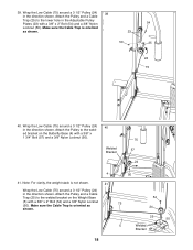
... 5 6 44. Attach the Pulley to the welded bracket on the Press Base (6) as shown. Route the Low Cable (75) through the welded bracket on the Weight Base (5) with a 3/8Ó x 1 3/4Ó Bolt (57) and a 3/8Ó Nylon Locknut (50). 22 57 50 24 75 43. 42. Wrap the Low Cable (75) around a 3 1/2Ó...
... 5 6 44. Attach the Pulley to the welded bracket on the Press Base (6) as shown. Route the Low Cable (75) through the welded bracket on the Weight Base (5) with a 3/8Ó x 1 3/4Ó Bolt (57) and a 3/8Ó Nylon Locknut (50). 22 57 50 24 75 43. 42. Wrap the Low Cable (75) around a 3 1/2Ó...

English Manual
Page 22
... 5 95 55. Remove the three preassembled 1/4Ó x 5/8Ó Screws 54 (95) from the Shroud (34). Attach the Seat Plate to the welded plate on the Weight Base (5) with a 1/4Ó Flat Washer (71) and a 1/4Ó Nylon Locknut (68). Insert a 1/4Ó x 2 1/2Ó Carriage Bolt (45) into the indicated ...the Shroud (34) to the indicated bracket on the 53 Butterfly Front Leg (3) with two 1/4Ó x 3/4Ó Bolts (49). Secure the other end of the Weight 55 Upright (9) with a 1/4Ó x 2 1/2Ó Bolt (79) and a 1/4Ó Flat Washer (71). 13 45 7 65 49 53. Attach the...
... 5 95 55. Remove the three preassembled 1/4Ó x 5/8Ó Screws 54 (95) from the Shroud (34). Attach the Seat Plate to the welded plate on the Weight Base (5) with a 1/4Ó Flat Washer (71) and a 1/4Ó Nylon Locknut (68). Insert a 1/4Ó x 2 1/2Ó Carriage Bolt (45) into the indicated ...the Shroud (34) to the indicated bracket on the 53 Butterfly Front Leg (3) with two 1/4Ó x 3/4Ó Bolts (49). Secure the other end of the Weight 55 Upright (9) with a 1/4Ó x 2 1/2Ó Bolt (79) and a 1/4Ó Flat Washer (71). 13 45 7 65 49 53. Attach the...

English Manual
Page 23
... other numbers refer to the 10 lb. See TROUBLE-SHOOTING AND MAINTENANCE on page 26 of the cables does not move smoothly over the pulleys. weight plates. Slide a Foam Pad (30) onto each end of the Pad Tube. Slide a Foam Pad (30) onto each end of the Pad Tube. 41 30... the indicated hole in the Press Front Leg (20). Make sure that the cables move smoothly, find and correct the problem. If there is used. Weight Plates Top 1 2 3 4 5 6 7 8 9 10 11 12 13 14 Leg Lever (lbs.) 19 31 43 55 68 81 92 105 117 129 141 154 166 178 190...
... other numbers refer to the 10 lb. See TROUBLE-SHOOTING AND MAINTENANCE on page 26 of the cables does not move smoothly over the pulleys. weight plates. Slide a Foam Pad (30) onto each end of the Pad Tube. Slide a Foam Pad (30) onto each end of the Pad Tube. 41 30... the indicated hole in the Press Front Leg (20). Make sure that the cables move smoothly, find and correct the problem. If there is used. Weight Plates Top 1 2 3 4 5 6 7 8 9 10 11 12 13 14 Leg Lever (lbs.) 19 31 43 55 68 81 92 105 117 129 141 154 166 178 190...

English Manual
Page 24
Incorrect cable routing can damage the weight system. Make sure that the Cables are routed correctly, that the pulleys move smoothly, and that the cable traps do not touch or bind the ...Cables. Cable Diagrams The Cable Diagrams below and on the next page show the correct route for each Cable. Ab Cable (74) 1 3 5 Weight Cable (72) 3 5 2 2 4 6 8 4 1 7 Butterfly Cable (73) 4 2 5 1 3 Cable ID Chart (73) 72 1/4Ó (72) 118 1/4Ó (74) 175 3/4Ó (75) 312 1/4Ó 24 The numbers show the...
Incorrect cable routing can damage the weight system. Make sure that the Cables are routed correctly, that the pulleys move smoothly, and that the cable traps do not touch or bind the ...Cables. Cable Diagrams The Cable Diagrams below and on the next page show the correct route for each Cable. Ab Cable (74) 1 3 5 Weight Cable (72) 3 5 2 2 4 6 8 4 1 7 Butterfly Cable (73) 4 2 5 1 3 Cable ID Chart (73) 72 1/4Ó (72) 118 1/4Ó (74) 175 3/4Ó (75) 312 1/4Ó 24 The numbers show the...

English Manual
Page 26
...Adjustment Handle (85) and slide the Backrest in the correct starting position for attaching any slack in the same manner. 99 85 Changing the Weight Setting To change the setting of the exercise will go. Adjust the Butterfly Seat (13, not shown) in the cables or chain as ...ments to the cables and pulleys, the amount of the attach- If there is performed, the effectiveness of the weight stack, insert a Weight Pin (19) under the desired Weight (21). Use the WEIGHT RESISTANCE CHART on page 27 to the Low Pulley Station, the High Pulley Station, or the Ab Pulley Station....
...Adjustment Handle (85) and slide the Backrest in the correct starting position for attaching any slack in the same manner. 99 85 Changing the Weight Setting To change the setting of the exercise will go. Adjust the Butterfly Seat (13, not shown) in the cables or chain as ...ments to the cables and pulleys, the amount of the attach- If there is performed, the effectiveness of the weight stack, insert a Weight Pin (19) under the desired Weight (21). Use the WEIGHT RESISTANCE CHART on page 27 to the Low Pulley Station, the High Pulley Station, or the Ab Pulley Station....

English Manual
Page 27
... first used on the back cover of cable used . Thread the bolt at the end of the Weight Cable into the Weight Tube (17) until the Cables are still too loose, move one of the Weight Cable (72) is felt, the Cables should be removed from the Adjustable Pulley Frame (23). Trouble-shooting...
... first used on the back cover of cable used . Thread the bolt at the end of the Weight Cable into the Weight Tube (17) until the Cables are still too loose, move one of the Weight Cable (72) is felt, the Cables should be removed from the Adjustable Pulley Frame (23). Trouble-shooting...

English Manual
Page 31
...Butterfly Grip Press Grip 5/16Ó x 2 3/4Ó Bolt Seat Adjustment Frame Curl Pad 5/16Ó x 2 1/2Ó Carriage Bolt Workout Decal Weight Insert 1/4Ó x 5/8Ó Screw Long Spacer Left Support Frame 1/2Ó Flat Washer Press Backrest 1/2Ó Plain Nut 1/4Ó x 1 1/2Ó...; Carriage Bolt 5/8Ó x 1/2Ó Spacer 1/4Ó x 1 1/2Ó Screw Plastic Weight Cover 1/2Ó x 3/4Ó Spacer 3/8Ó x 1 1/4Ó Button Head Bolt UserÕs Manual Note: Ò#Ó indicates a non-illustrated part....
...Butterfly Grip Press Grip 5/16Ó x 2 3/4Ó Bolt Seat Adjustment Frame Curl Pad 5/16Ó x 2 1/2Ó Carriage Bolt Workout Decal Weight Insert 1/4Ó x 5/8Ó Screw Long Spacer Left Support Frame 1/2Ó Flat Washer Press Backrest 1/2Ó Plain Nut 1/4Ó x 1 1/2Ó...; Carriage Bolt 5/8Ó x 1/2Ó Spacer 1/4Ó x 1 1/2Ó Screw Plastic Weight Cover 1/2Ó x 3/4Ó Spacer 3/8Ó x 1 1/4Ó Button Head Bolt UserÕs Manual Note: Ò#Ó indicates a non-illustrated part....


