
English Manual
Page 4
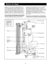
... yourself with the major parts of the training system. The serial number can be found on a decal attached to achieve the results you for selecting the versatile NordicTrack¨ GRT500 training system. Shroud Backrest Backrest Adjustment Tube High Pulley Station Lat Bar Warning Decal No.... 1 Warning Decal No. 2 AB Pulley Station Press/Fly Arm Curl Pad Seat Weight Stack Warning Decal No. 1 Leg Lever Low Pulley Station Foot...
... yourself with the major parts of the training system. The serial number can be found on a decal attached to achieve the results you for selecting the versatile NordicTrack¨ GRT500 training system. Shroud Backrest Backrest Adjustment Tube High Pulley Station Lat Bar Warning Decal No.... 1 Warning Decal No. 2 AB Pulley Station Press/Fly Arm Curl Pad Seat Weight Stack Warning Decal No. 1 Leg Lever Low Pulley Station Foot...
English Manual
Page 6
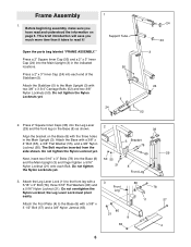
... Main Upright (3) with two 3/8Ó x 3 3/4Ó Carriage Bolts (52) and two 3/8Ó Nylon Locknuts (50). Attach the Stabilizer (5) to the Base (8) with the three holes in the indicated locations. 50 Press a 2Ó x 3Ó Inner Cap (24) into the Base (8) and the Main Upright (3) and finger tighten a ...5/16Ó Nylon Locknut (21) onto each end of the Stabilizer (5). Press 2Ó Square Inner Caps (33) into the Leg Lever 2 (29) and the front leg on the Base (8) as shown. 33 Align the bracket on page 5. Do not overtighten the Nylon Locknut;...
... Main Upright (3) with two 3/8Ó x 3 3/4Ó Carriage Bolts (52) and two 3/8Ó Nylon Locknuts (50). Attach the Stabilizer (5) to the Base (8) with the three holes in the indicated locations. 50 Press a 2Ó x 3Ó Inner Cap (24) into the Base (8) and the Main Upright (3) and finger tighten a ...5/16Ó Nylon Locknut (21) onto each end of the Stabilizer (5). Press 2Ó Square Inner Caps (33) into the Leg Lever 2 (29) and the front leg on the Base (8) as shown. 33 Align the bracket on page 5. Do not overtighten the Nylon Locknut;...
English Manual
Page 10
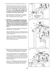
...13 1 Wrap the High Cable (73) over a 4Ó Pulley (35). Save the 3/8Ó 92 x 1 3/4Ó Bolt (60) and the 3/8Ó Nylon Locknut (63). 71 Attach the Pulley Bracket (91) to this manual. To assemble the accessory, refer the userÕs manual accompanying it holds the Cable in the Pulley Bracket...Bushings (42), and a 3/8Ó Nylon Jamnut (63). 35 63 55 42 Bolt 73 Slot 42 55 54 14. 12. After you purchased the optional leg press accessory (NTSA03990), please disregard steps 14 and 15 in this manual and continue with step 16 on the High Cable back down through the indicated...
...13 1 Wrap the High Cable (73) over a 4Ó Pulley (35). Save the 3/8Ó 92 x 1 3/4Ó Bolt (60) and the 3/8Ó Nylon Locknut (63). 71 Attach the Pulley Bracket (91) to this manual. To assemble the accessory, refer the userÕs manual accompanying it holds the Cable in the Pulley Bracket...Bushings (42), and a 3/8Ó Nylon Jamnut (63). 35 63 55 42 Bolt 73 Slot 42 55 54 14. 12. After you purchased the optional leg press accessory (NTSA03990), please disregard steps 14 and 15 in this manual and continue with step 16 on the High Cable back down through the indicated...

English Manual
Page 11
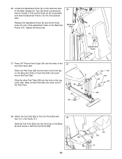
... the Low Cable (72) through the indicated slots in the direction shown. Route the small ball on the other. Attach a 4Ó Pulley (35) inside the bottom of the Spacer and the Tab. Press a 2Ó Square Inner Cap (33) into the top of the High Cable (73) up through the indicated slot in... Upright (3) with a 1/4Ó x 1Ó Bolt (98), a Fender Washer (97), and a 1/4Ó Nylon Locknut (25). Wrap the High Cable around a 4Ó Pulley (35) in the Leg Lever (29) and the front leg on the end of the Weight Tube (36). 15 42 63 1 42 35 73 73 Bolt 36 55 54 16. 15.
... the Low Cable (72) through the indicated slots in the direction shown. Route the small ball on the other. Attach a 4Ó Pulley (35) inside the bottom of the Spacer and the Tab. Press a 2Ó Square Inner Cap (33) into the top of the High Cable (73) up through the indicated slot in... Upright (3) with a 1/4Ó x 1Ó Bolt (98), a Fender Washer (97), and a 1/4Ó Nylon Locknut (25). Wrap the High Cable around a 4Ó Pulley (35) in the Leg Lever (29) and the front leg on the end of the Weight Tube (36). 15 42 63 1 42 35 73 73 Bolt 36 55 54 16. 15.
English Manual
Page 14
...onto each end of the Main Upright (3). Locate the Adjustment Knob (9) on the Backrest Frame (15). Attach the Curl Pad (82) to loosen it with 28 four 1/4Ó x 3/4Ó Bolts (17).... Pad Tube (28) into the ends of the Pad Tube. Slide the Curl Post (83) onto the front leg on the Base (8). Turn the Knob counterclockwise to the Curl Post (83) with the Curl Knob (89). 17...possible and slide the Backrest Frame (15) into the hole in the Leg Lever (29). Press 3/4Ó Round Inner Caps (34) into the hole in the front leg on the Base (8) and secure it . Tighten the Knob fully. ...
...onto each end of the Main Upright (3). Locate the Adjustment Knob (9) on the Backrest Frame (15). Attach the Curl Pad (82) to loosen it with 28 four 1/4Ó x 3/4Ó Bolts (17).... Pad Tube (28) into the ends of the Pad Tube. Slide the Curl Post (83) onto the front leg on the Base (8). Turn the Knob counterclockwise to the Curl Post (83) with the Curl Knob (89). 17...possible and slide the Backrest Frame (15) into the hole in the Leg Lever (29). Press 3/4Ó Round Inner Caps (34) into the hole in the front leg on the Base (8) and secure it . Tighten the Knob fully. ...
English Manual
Page 25
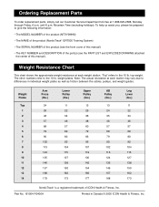
... Weight Plates Top 1 2 3 4 5 6 7 8 9 10 11 12 13 14 Arm Press (lbs.) 24 35 46 57 68 79 90 102 113 124 135 146 157 168 179 Lower Pulley...35 46 57 68 79 90 102 113 124 135 146 157 168 Leg Lever (lbs.) 11 22 34 46 57 69 80 92 104 115 127 138 150 162 173 NordicTrack¨ is a registered trademark of this manual). Part No. 161904 ...cover of this manual) ¥ The KEY NUMBER and DESCRIPTION of the part(s) (see the PART LIST and EXPLODED DRAWING attached the center of ICON Health & Fitness, Inc. weight plates. Weight Resistance Chart This chart shows the approximate weight resistance at...
... Weight Plates Top 1 2 3 4 5 6 7 8 9 10 11 12 13 14 Arm Press (lbs.) 24 35 46 57 68 79 90 102 113 124 135 146 157 168 179 Lower Pulley...35 46 57 68 79 90 102 113 124 135 146 157 168 Leg Lever (lbs.) 11 22 34 46 57 69 80 92 104 115 127 138 150 162 173 NordicTrack¨ is a registered trademark of this manual). Part No. 161904 ...cover of this manual) ¥ The KEY NUMBER and DESCRIPTION of the part(s) (see the PART LIST and EXPLODED DRAWING attached the center of ICON Health & Fitness, Inc. weight plates. Weight Resistance Chart This chart shows the approximate weight resistance at...


