
English Manual
Page 1
... satisfaction through direct assistance from our factory. The serial number is found in the space above. TO AVOID UNNECESSARY DELAYS, PLEASE CALL DIRECT TO OUR TOLL-FREE CUSTOMER HOT LINE. MST CAUTION Read all precautions and instructions in this manual before using this manual for future reference. ¨ USERÕS MANUAL Visit our website at www.nordictrack.com new products, prizes, fitness tips, and...
... satisfaction through direct assistance from our factory. The serial number is found in the space above. TO AVOID UNNECESSARY DELAYS, PLEASE CALL DIRECT TO OUR TOLL-FREE CUSTOMER HOT LINE. MST CAUTION Read all precautions and instructions in this manual before using this manual for future reference. ¨ USERÕS MANUAL Visit our website at www.nordictrack.com new products, prizes, fitness tips, and...

English Manual
Page 2
... set out in the center of all other warranties and any defected part for replacement or, if necessary, the entire product, for service where your UserÕs Manual (ÒManualÓ). Table of Contents Limited Warranty 2 Important Precautions 3 Before You Begin 4 Assembly 5 Cable Diagram 16 Adjustment 17 Trouble-shooting and Maintenance 19 Ordering Replacement Parts Back Cover Weight Resistance Chart Back Cover Note: A PART LIST/EXPLODED DRAWING and a PART IDENTIFICATION CHART are performed by an ICON trained and authorized service...
... set out in the center of all other warranties and any defected part for replacement or, if necessary, the entire product, for service where your UserÕs Manual (ÒManualÓ). Table of Contents Limited Warranty 2 Important Precautions 3 Before You Begin 4 Assembly 5 Cable Diagram 16 Adjustment 17 Trouble-shooting and Maintenance 19 Ordering Replacement Parts Back Cover Weight Resistance Chart Back Cover Note: A PART LIST/EXPLODED DRAWING and a PART IDENTIFICATION CHART are performed by an ICON trained and authorized service...
English Manual
Page 3
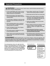
... owner to ensure that could cause the training only. ICON assumes no responsibility for home use them. 7. Use the training system only on the training system in the accompanying literature before using the training system. 3. Replace any exercise program, consult your physician. Note that does not use ing an exercise that all users of the training system are adequately informed of the pulleys. 11. Always stand on all instructions before using...
... owner to ensure that could cause the training only. ICON assumes no responsibility for home use them. 7. Use the training system only on the training system in the accompanying literature before using the training system. 3. Replace any exercise program, consult your physician. Note that does not use ing an exercise that all users of the training system are adequately informed of the pulleys. 11. Always stand on all instructions before using...
English Manual
Page 4
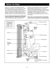
... major parts of the training system. Mountain Time (excluding holidays). For your goal is NTSY09990. Please refer to the GRT500 (see the front cover of the body. ASSEMBLED DIMENSIONS: Height: 81 in. Shroud Backrest Backrest Adjustment Tube High Pulley Station Lat Bar Warning Decal No. 1 Warning Decal No. 2 AB Pulley Station Press/Fly Arm Curl Pad Seat Weight Stack Warning Decal No. 1 Leg Lever Low Pulley Station...
... major parts of the training system. Mountain Time (excluding holidays). For your goal is NTSY09990. Please refer to the GRT500 (see the front cover of the body. ASSEMBLED DIMENSIONS: Height: 81 in. Shroud Backrest Backrest Adjustment Tube High Pulley Station Lat Bar Warning Decal No. 1 Warning Decal No. 2 AB Pulley Station Press/Fly Arm Curl Pad Seat Weight Stack Warning Decal No. 1 Leg Lever Low Pulley Station...
English Manual
Page 5
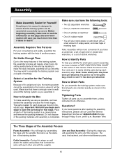
...; Two (2) adjustable wrenches ¥ One (1) standard screwdriver ¥ One (1) phillips screwdriver ¥ One (1) rubber mallet ¥ You will attach the cables and pulleys that connect the arms with the weights. 5 How to read it to make sure that all parts as possible, we have divided the assembly process into three stages. Arm and Seat AssemblyÑDuring this page; By setting aside plenty...
...; Two (2) adjustable wrenches ¥ One (1) standard screwdriver ¥ One (1) phillips screwdriver ¥ One (1) rubber mallet ¥ You will attach the cables and pulleys that connect the arms with the weights. 5 How to read it to make sure that all parts as possible, we have divided the assembly process into three stages. Arm and Seat AssemblyÑDuring this page; By setting aside plenty...
English Manual
Page 6
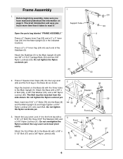
...two 5/16Ó x 3Ó Bolts (78) into each Bolt. Attach the Stabilizer (5) to the front leg with the three holes in the indicated locations. 50 Press a 2Ó x 3Ó Inner Cap (24) into the Base (8) and the Main Upright (3) and finger tighten a 5/16Ó Nylon Locknut (...3 Front Leg 80 11 80 21 8 63 78 57 4 6 Attach the Base with two 3/8Ó x 3 3/4Ó Carriage Bolts (52) and two 3/8Ó Nylon Locknuts (50). Before beginning assembly, make sure you much more time than it ! 1 Support Tube Open the parts bag labeled ÒFRAME ASSEMBLY.Ó Press a 2Ó...
...two 5/16Ó x 3Ó Bolts (78) into each Bolt. Attach the Stabilizer (5) to the front leg with the three holes in the indicated locations. 50 Press a 2Ó x 3Ó Inner Cap (24) into the Base (8) and the Main Upright (3) and finger tighten a 5/16Ó Nylon Locknut (...3 Front Leg 80 11 80 21 8 63 78 57 4 6 Attach the Base with two 3/8Ó x 3 3/4Ó Carriage Bolts (52) and two 3/8Ó Nylon Locknuts (50). Before beginning assembly, make sure you much more time than it ! 1 Support Tube Open the parts bag labeled ÒFRAME ASSEMBLY.Ó Press a 2Ó...
English Manual
Page 7
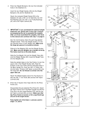
... parts bag labeled ÒWeight InsertsÓ. Press two Weight Inserts (77) into the Weight Bumpers (19) and the Stabilizer (5). Fully tighten all of the Weights (26) onto the Weight Guides (23). The holes must be on page 8. Slide all of the Weight Guides (23). Attach the indicated Weight Guide (23) to assemble the weights. Attach the Press Frame (12) to the Main Upright (3) with the indicated holes in steps...
... parts bag labeled ÒWeight InsertsÓ. Press two Weight Inserts (77) into the Weight Bumpers (19) and the Stabilizer (5). Fully tighten all of the Weights (26) onto the Weight Guides (23). The holes must be on page 8. Slide all of the Weight Guides (23). Attach the indicated Weight Guide (23) to assemble the weights. Attach the Press Frame (12) to the Main Upright (3) with the indicated holes in steps...
English Manual
Page 8
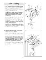
... Slot 54 35 55 Identify the High Cable (73), which has a ball on one end and a bolt on page 16 as you assemble the cables. Cable Assembly 7 7. Open the parts bags labeled ÒCABLE ASSEMBLYÓ and Ò4 PULLEYSÓ. Feed almost all of the High Cable (73) with the bolt. Remove the upper 3/8Ó x 3Ó Bolt (45) from the Top Frame (1) and the Main Upright (3).
... Slot 54 35 55 Identify the High Cable (73), which has a ball on one end and a bolt on page 16 as you assemble the cables. Cable Assembly 7 7. Open the parts bags labeled ÒCABLE ASSEMBLYÓ and Ò4 PULLEYSÓ. Feed almost all of the High Cable (73) with the bolt. Remove the upper 3/8Ó x 3Ó Bolt (45) from the Top Frame (1) and the Main Upright (3).

English Manual
Page 9
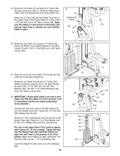
.... Wrap the High Cable around another 4Ó Pulley (35). Feed the bolt on the Press Frame (12) as shown. Wrap the High Cable (73) around a 4Ó Pulley (35). Wrap the High Cable (73) around a 4Ó Pulley (35) in 10 the direction shown. Wrap the High Cable (73) around a 4Ó Pulley (35) in the direction shown. Feed the bolt on the High Cable (73) under...
.... Wrap the High Cable around another 4Ó Pulley (35). Feed the bolt on the Press Frame (12) as shown. Wrap the High Cable (73) around a 4Ó Pulley (35). Wrap the High Cable (73) around a 4Ó Pulley (35) in 10 the direction shown. Wrap the High Cable (73) around a 4Ó Pulley (35) in the direction shown. Feed the bolt on the High Cable (73) under...
English Manual
Page 10
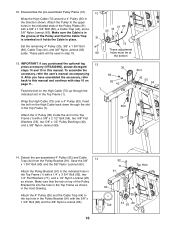
... Jamnut (63). Feed the bolt on the High Cable (73) up through the slot in place. Save the 3/8Ó 92 x 1 3/4Ó Bolt (60) and the 3/8Ó Nylon Locknut (63). 71 Attach the Pulley Bracket (91) to this manual. After you purchased the optional leg press accessory (NTSA03990), please disregard steps 14 and 15 in the Pulley Bracket (91) with the...
... Jamnut (63). Feed the bolt on the High Cable (73) up through the slot in place. Save the 3/8Ó 92 x 1 3/4Ó Bolt (60) and the 3/8Ó Nylon Locknut (63). 71 Attach the Pulley Bracket (91) to this manual. After you purchased the optional leg press accessory (NTSA03990), please disregard steps 14 and 15 in the Pulley Bracket (91) with the...

English Manual
Page 11
... drawing. Wrap the High Cable around a 4Ó Pulley (35) in the front leg of the Weight Tube (36). 15 42 63 1 42 35 73 73 Bolt 36 55 54 16. Attach a 4Ó Pulley (35) inside the slot in the direction shown. Feed the bolt on the end of the Leg Lever (29). 16 72... x 1Ó Bolt (98), a Fender Washer (97), and a 1/4Ó Nylon Locknut (25). Attach the Spacer (94) inside the slot in the Main Upright (3) and the Base (8). 35 62 Wrap the Low Cable (72) around two 4Ó Pulleys (35). Press the Tab (93) onto the cage as shown. Attach the Pulleys inside the bottom ...
... drawing. Wrap the High Cable around a 4Ó Pulley (35) in the front leg of the Weight Tube (36). 15 42 63 1 42 35 73 73 Bolt 36 55 54 16. Attach a 4Ó Pulley (35) inside the slot in the direction shown. Feed the bolt on the end of the Leg Lever (29). 16 72... x 1Ó Bolt (98), a Fender Washer (97), and a 1/4Ó Nylon Locknut (25). Attach the Spacer (94) inside the slot in the Main Upright (3) and the Base (8). 35 62 Wrap the Low Cable (72) around two 4Ó Pulleys (35). Press the Tab (93) onto the cage as shown. Attach the Pulleys inside the bottom ...
English Manual
Page 12
... pulleys move smoothly. Slide the Pulley and a Cable Trap (44) between the two Pulley Plates (31). 31 Attach the 4Ó Pulley (35) and the Cable Trap (44) to tighten both cables from the Weight Tube (36). Insert the Weight Pin (39) under one of the High Cable (73) from end to the welded bracket on top of the pulleys and that was removed in the Main Upright...
... pulleys move smoothly. Slide the Pulley and a Cable Trap (44) between the two Pulley Plates (31). 31 Attach the 4Ó Pulley (35) and the Cable Trap (44) to tighten both cables from the Weight Tube (36). Insert the Weight Pin (39) under one of the High Cable (73) from end to the welded bracket on top of the pulleys and that was removed in the Main Upright...
English Manual
Page 13
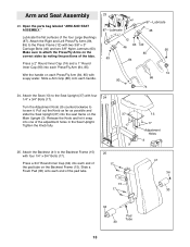
... Frame (15). Slide a Foam Pad (30) onto each Press/Fly Arm (84, 85). Open the parts bag labeled ÒARM AND SEAT ASSEMBLY.Ó Lubricate the flat surfaces of the pad tube. 13 17 Adjustment Holes 3 41 34 15 17 30 34 30 Pad Tube 13 Attach the Right and Left Press/Fly Arms (84, 85) to loosen it snap into each...
... Frame (15). Slide a Foam Pad (30) onto each Press/Fly Arm (84, 85). Open the parts bag labeled ÒARM AND SEAT ASSEMBLY.Ó Lubricate the flat surfaces of the pad tube. 13 17 Adjustment Holes 3 41 34 15 17 30 34 30 Pad Tube 13 Attach the Right and Left Press/Fly Arms (84, 85) to loosen it snap into each...
English Manual
Page 14
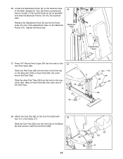
...(83) with the Curl Knob (89). 17 89 14 82 83 8 Press 3/4Ó Round Inner Caps (34) into the hole in the Leg Lever (29). Slide the Curl Post (83) onto the front leg on the Backrest Frame (15). Tighten the Knob fully. 26 Backrest Tube 3 15 9 Adjustment Holes 27. Locate the Adjustment Knob (9) on the Base (8).... end of the Main Upright (3). Release the Adjustment Knob (9) and let the Knob snap into one Pad Tube (28) into the ends of the Pad Tube. 34 30 34 8 30 34 30 28 34 29 28. Slide the other Pad Tube (28) into the backrest tube. 26. Attach the Curl Pad (82...
...(83) with the Curl Knob (89). 17 89 14 82 83 8 Press 3/4Ó Round Inner Caps (34) into the hole in the Leg Lever (29). Slide the Curl Post (83) onto the front leg on the Backrest Frame (15). Tighten the Knob fully. 26 Backrest Tube 3 15 9 Adjustment Holes 27. Locate the Adjustment Knob (9) on the Base (8).... end of the Main Upright (3). Release the Adjustment Knob (9) and let the Knob snap into one Pad Tube (28) into the ends of the Pad Tube. 34 30 34 8 30 34 30 28 34 29 28. Slide the other Pad Tube (28) into the backrest tube. 26. Attach the Curl Pad (82...
English Manual
Page 15
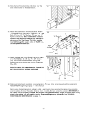
... Screws must be explained in the Shroud and into the Tinnerman Clips (38). See TROUBLESHOOTING AND MAINTENANCE on page 17 of the Top Frame. The Bolts must be damaged when heavy weight is used. Do not tighten the Bolts yet. 30 ÒLÓ-Brackets Align Corners 71 17 56 1 17 71 25 31. Before using the training system, pull each cable...
... Screws must be explained in the Shroud and into the Tinnerman Clips (38). See TROUBLESHOOTING AND MAINTENANCE on page 17 of the Top Frame. The Bolts must be damaged when heavy weight is used. Do not tighten the Bolts yet. 30 ÒLÓ-Brackets Align Corners 71 17 56 1 17 71 25 31. Before using the training system, pull each cable...

English Manual
Page 17
... attaching the lat bar, row bar, ankle strap, or ab strap, make sure that it snaps into one of the exercise will be performed. Pull out the Knob as far as an exercise is in the Seat Upright. Adjustment The instructions below describe how each part of the weight stack, insert the Weight Pin (39) under the desired Weight (26). Note: Due to the cables and pulleys, the amount of resistance...
... attaching the lat bar, row bar, ankle strap, or ab strap, make sure that it snaps into one of the exercise will be performed. Pull out the Knob as far as an exercise is in the Seat Upright. Adjustment The instructions below describe how each part of the weight stack, insert the Weight Pin (39) under the desired Weight (26). Note: Due to the cables and pulleys, the amount of resistance...
English Manual
Page 18
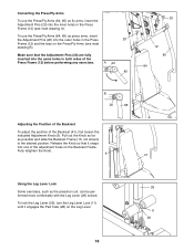
... retighten the Knob. 9 41 Using the Leg Lever Lock Some exercises, such as possible and slide the Backrest Frame (15, not shown) to the desired position. Make sure that it engages the Pad Tube (28) on the Leg Lever. 18 29 11 28 Converting the Press/Fly Arms To use the Press/Fly Arms (84, 85) as press arms, insert the Adjustment Pins (20...
... retighten the Knob. 9 41 Using the Leg Lever Lock Some exercises, such as possible and slide the Backrest Frame (15, not shown) to the desired position. Make sure that it engages the Pad Tube (28) on the Leg Lever. 18 29 11 28 Converting the Press/Fly Arms To use the Press/Fly Arms (84, 85) as press arms, insert the Adjustment Pins (20...
English Manual
Page 19
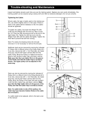
... re-attach it is first used on the training sys- 73 tem, can also be removed by moving the indicated 4Ó Pulleys (35) to different holes in the cables before resistance is felt, the cables Bolt should be removed by moving the indicated 4Ó Pulley (35) to a higher hole and reattach it . Trouble-shooting and Maintenance Inspect and tighten all parts each time you use solvents. Tightening the Cables Woven cable...
... re-attach it is first used on the training sys- 73 tem, can also be removed by moving the indicated 4Ó Pulleys (35) to different holes in the cables before resistance is felt, the cables Bolt should be removed by moving the indicated 4Ó Pulley (35) to a higher hole and reattach it . Trouble-shooting and Maintenance Inspect and tighten all parts each time you use solvents. Tightening the Cables Woven cable...
English Manual
Page 23
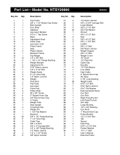
... Weight Insert 5/16Ó x 3Ó Bolt 5/16Ó Nylon Jamnut 5/16Ó Flat Washer Exercise Guide Decal Curl Pad Curl Post Right Press/Fly Arm Left Press/Fly Arm Arm Grip Large Bushing 1/2Ó x 3/4Ó Bushing Curl Knob 1Ó Round Inner Cap Pulley Bracket 1/4Ó x 3 3/4Ó Bolt Tab Spacer Hole Plug 5/16Ó x 2 1/2Ó Bolt Fender Washer 1/4Ó x 1Ó Bolt UserÕs Manual Exercise Poster NTSY09990 Key No. Part ListÑModel...
... Weight Insert 5/16Ó x 3Ó Bolt 5/16Ó Nylon Jamnut 5/16Ó Flat Washer Exercise Guide Decal Curl Pad Curl Post Right Press/Fly Arm Left Press/Fly Arm Arm Grip Large Bushing 1/2Ó x 3/4Ó Bushing Curl Knob 1Ó Round Inner Cap Pulley Bracket 1/4Ó x 3 3/4Ó Bolt Tab Spacer Hole Plug 5/16Ó x 2 1/2Ó Bolt Fender Washer 1/4Ó x 1Ó Bolt UserÕs Manual Exercise Poster NTSY09990 Key No. Part ListÑModel...
English Manual
Page 25
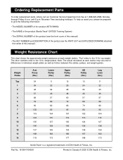
... Training System) ¥ The SERIAL NUMBER of the product (see the PART LIST and EXPLODED DRAWING attached the center of ICON Health & Fitness, Inc. Mountain Time (excluding holidays). The other numbers refer to the 10 lb. weight plates. Part No. 161904 R0400A Printed in individual weight plates as well as friction between the cables, pulleys, and weight guides. Ordering Replacement Parts To order replacement parts, simply call our Customer Service Department toll-free...
... Training System) ¥ The SERIAL NUMBER of the product (see the PART LIST and EXPLODED DRAWING attached the center of ICON Health & Fitness, Inc. Mountain Time (excluding holidays). The other numbers refer to the 10 lb. weight plates. Part No. 161904 R0400A Printed in individual weight plates as well as friction between the cables, pulleys, and weight guides. Ordering Replacement Parts To order replacement parts, simply call our Customer Service Department toll-free...


