
User Manual
Page 1
... equipment. Write the serial number in this manual before contacting Customer Care. CALL TOLL-FREE: 1-800-TO-BE-FIT (1-800-862-3348) Mon.-Fri. 6 a.m.-6 p.m. www.nordictrack.com Model No. IMPORTANT: Please register this product (see the limited warranty on the back cover of this manual) before using this manual for reference...
... equipment. Write the serial number in this manual before contacting Customer Care. CALL TOLL-FREE: 1-800-TO-BE-FIT (1-800-862-3348) Mon.-Fri. 6 a.m.-6 p.m. www.nordictrack.com Model No. IMPORTANT: Please register this product (see the limited warranty on the back cover of this manual) before using this manual for reference...

User Manual
Page 2
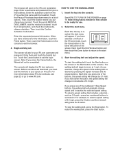
Apply the decal in the location shown. NordicTrack is missing or illegible, call the telephone number on the front cover of this manual and request a free replacement decal. Note: The decals may not ... PLACEMENT 2 IMPORTANT PRECAUTIONS 3 BEFORE YOU BEGIN 5 ASSEMBLY 6 HOW TO USE THE CHEST PULSE SENSOR 13 OPERATION AND ADJUSTMENT 14 HOW TO FOLD AND MOVE THE TREADMILL 29 TROUBLESHOOTING 30 EXERCISE GUIDELINES 33 PART LIST 34 EXPLODED DRAWING 36 ORDERING REPLACEMENT PARTS Back Cover LIMITED WARRANTY Back Cover WARNING DECAL PLACEMENT This...
Apply the decal in the location shown. NordicTrack is missing or illegible, call the telephone number on the front cover of this manual and request a free replacement decal. Note: The decals may not ... PLACEMENT 2 IMPORTANT PRECAUTIONS 3 BEFORE YOU BEGIN 5 ASSEMBLY 6 HOW TO USE THE CHEST PULSE SENSOR 13 OPERATION AND ADJUSTMENT 14 HOW TO FOLD AND MOVE THE TREADMILL 29 TROUBLESHOOTING 30 EXERCISE GUIDELINES 33 PART LIST 34 EXPLODED DRAWING 36 ORDERING REPLACEMENT PARTS Back Cover LIMITED WARRANTY Back Cover WARNING DECAL PLACEMENT This...
User Manual
Page 3
... you are adequately informed of this manual and all warnings and precautions. 3. This is not working properly.) 8. Do not place the treadmill on your treadmill before using your local NordicTrack dealer or call the telephone number on the front cover of high speeds. ICON assumes no responsibility for personal injury or property damage...
... you are adequately informed of this manual and all warnings and precautions. 3. This is not working properly.) 8. Do not place the treadmill on your treadmill before using your local NordicTrack dealer or call the telephone number on the front cover of high speeds. ICON assumes no responsibility for personal injury or property damage...
User Manual
Page 4
...the storage position. 23. If you feel faint or if you experience pain while exercising, stop immediately and cool down. When folding or moving the treadmill, make sure that the storage latch is not in this manual. vice representative. nance and adjustment procedures described in a commercial, rental, or institutional...26. Always remove the key, unplug the power cord, and press the power switch into any object into the off position when the treadmill is holding the frame securely in serious injury or death. Never remove the motor hood un- less instructed to raise, lower, or move ...
...the storage position. 23. If you feel faint or if you experience pain while exercising, stop immediately and cool down. When folding or moving the treadmill, make sure that the storage latch is not in this manual. vice representative. nance and adjustment procedures described in a commercial, rental, or institutional...26. Always remove the key, unplug the power cord, and press the power switch into any object into the off position when the treadmill is holding the frame securely in serious injury or death. Never remove the motor hood un- less instructed to raise, lower, or move ...
User Manual
Page 5
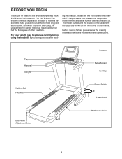
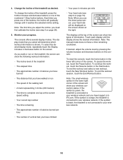
... when you have questions after read this manual carefully before contacting us assist you for selecting the revolutionary NordicTrack® ELITE 9500 PRO treadmill. The model number and the location of the serial number decal are shown on the front cover of ... Upright Console Pulse Sensor Key/Clip Walking Belt Foot Rail Power Switch Power Cord Idler Roller Adjustment Bolts Platform Cushion 5 The ELITE 9500 PRO treadmill offers an impressive selection of this manual. Before reading further, please review the drawing below and familiarize yourself with the labeled parts...
... when you have questions after read this manual carefully before contacting us assist you for selecting the revolutionary NordicTrack® ELITE 9500 PRO treadmill. The model number and the location of the serial number decal are shown on the front cover of ... Upright Console Pulse Sensor Key/Clip Walking Belt Foot Rail Power Switch Power Cord Idler Roller Adjustment Bolts Platform Cushion 5 The ELITE 9500 PRO treadmill offers an impressive selection of this manual. Before reading further, please review the drawing below and familiarize yourself with the labeled parts...
User Manual
Page 6
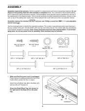
...high-performance lubricant. Attach the Right Wheel Cap (not shown) to protect the floor or carpet. Note: The underside of the treadmill walking belt is lubricant on top of this manual. Place a piece of the 1 Frame (56) to the right side ... . If there is coated with two #8 x 3/4" Screws (1). ASSEMBLY Assembly requires two persons. To avoid damaging parts, do not use power tools for assembly. Set the treadmill in the same way. 97 1 6 56 96 Cardboard During shipping, some lubricant may be included. #8 x 1/2" Ground Screw (9)-1 #8 x 3/4" Screw (1)-4 3/8" Star Washer (...
...high-performance lubricant. Attach the Right Wheel Cap (not shown) to protect the floor or carpet. Note: The underside of the treadmill walking belt is lubricant on top of this manual. Place a piece of the 1 Frame (56) to the right side ... . If there is coated with two #8 x 3/4" Screws (1). ASSEMBLY Assembly requires two persons. To avoid damaging parts, do not use power tools for assembly. Set the treadmill in the same way. 97 1 6 56 96 Cardboard During shipping, some lubricant may be included. #8 x 1/2" Ground Screw (9)-1 #8 x 3/4" Screw (1)-4 3/8" Star Washer (...
User Manual
Page 7
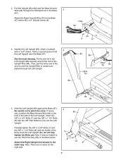
Hole 84 3. Identify the Left Upright (89), which is routed completely through the indicated hole in the same way. See the inset drawing. Tie the wire tie in the side of the Bolts touch the Left Upright (89); Hold the Left Upright (89) against the Base (97). Then, pull the other end of the Upright Wire (84). Note: It may be helpful to pinch the wires. Note: There are no wires on the Bolt shown. Be careful not to use the Short Hex Key (63) on the right side. 4 89 7 12 94 8 12 7 63 97 If necessary, position the Base Ground Wire (94) in the hole in the Left ...
Hole 84 3. Identify the Left Upright (89), which is routed completely through the indicated hole in the same way. See the inset drawing. Tie the wire tie in the side of the Bolts touch the Left Upright (89); Hold the Left Upright (89) against the Base (97). Then, pull the other end of the Upright Wire (84). Note: It may be helpful to pinch the wires. Note: There are no wires on the Bolt shown. Be careful not to use the Short Hex Key (63) on the right side. 4 89 7 12 94 8 12 7 63 97 If necessary, position the Base Ground Wire (94) in the hole in the Left ...
User Manual
Page 8
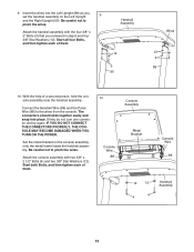
Set the handrail assembly face down on a soft 6 surface to avoid scratching the handrail assem- Handrail Assembly 8 Slide the Right Base Cover onto the Right Upright (90). Slide the Left Base Cover onto the Left Upright (89). 5. Do not press the Base Covers into place yet. 90 89 93 92 6. Identify the Left Base Cover (92) and the Right 5 Base Cover (93). The Brackets will be used in step 7 and the Bolts will be used in step 9. bly. 3 Remove two 3/8" x 2" Bolts (3) and a Handrail Bracket (85) from each side of the handrail as- 85 sembly.
Set the handrail assembly face down on a soft 6 surface to avoid scratching the handrail assem- Handrail Assembly 8 Slide the Right Base Cover onto the Right Upright (90). Slide the Left Base Cover onto the Left Upright (89). 5. Do not press the Base Covers into place yet. 90 89 93 92 6. Identify the Left Base Cover (92) and the Right 5 Base Cover (93). The Brackets will be used in step 7 and the Bolts will be used in step 9. bly. 3 Remove two 3/8" x 2" Bolts (3) and a Handrail Bracket (85) from each side of the handrail as- 85 sembly.
User Manual
Page 9
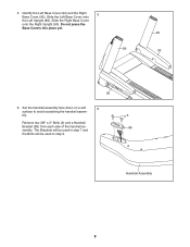
See the inset drawing. Connect the Upright Wire (84) to the Handrail Wire (86). Orient each of a second person, hold the 8 handrail assembly near the Left Upright (89). With the help of them. 7 Long Tab 84 Long Tab Large 2 Holes 12 85 89 2 12 85 90 8. 7. If they do not, turn one connector and try again. Route the Upright Wire (84) through the center hole in the position shown and the large holes are on top. IF YOU DO NOT CONNECT THE CONNECTORS PROPERLY, THE CONSOLE MAY BECOME DAMAGED WHEN YOU TURN ON THE POWER. Then, remove the wire tie from the Uprights (89,...
See the inset drawing. Connect the Upright Wire (84) to the Handrail Wire (86). Orient each of a second person, hold the 8 handrail assembly near the Left Upright (89). With the help of them. 7 Long Tab 84 Long Tab Large 2 Holes 12 85 89 2 12 85 90 8. 7. If they do not, turn one connector and try again. Route the Upright Wire (84) through the center hole in the position shown and the large holes are on top. IF YOU DO NOT CONNECT THE CONNECTORS PROPERLY, THE CONSOLE MAY BECOME DAMAGED WHEN YOU TURN ON THE POWER. Then, remove the wire tie from the Uprights (89,...
User Manual
Page 10
9. With the help of them . IF YOU DO NOT CONNECT THE CONNECTORS PROPERLY, THE CONSOLE MAY BECOME DAMAGED WHEN YOU TURN ON THE POWER. Set the metal bracket on the Left Upright 9 and the Right Upright (90). Start both Bolts, and then tighten each of them . 10 Console Wire 88 Console Assembly Metal Bracket Console Wire 86 12 12 4 4 Handrail Assembly 10 Attach the handrail assembly with two 3/8" x 2 1/2" Bolts (4) and two 3/8" Star Washers (12). Handrail Assembly 12 3 90 Wires 12 3 89 10. Connect the Handrail Wire (86) and the Pulse Wire (88) to pinch the wires...
9. With the help of them . IF YOU DO NOT CONNECT THE CONNECTORS PROPERLY, THE CONSOLE MAY BECOME DAMAGED WHEN YOU TURN ON THE POWER. Set the metal bracket on the Left Upright 9 and the Right Upright (90). Start both Bolts, and then tighten each of them . 10 Console Wire 88 Console Assembly Metal Bracket Console Wire 86 12 12 4 4 Handrail Assembly 10 Attach the handrail assembly with two 3/8" x 2 1/2" Bolts (4) and two 3/8" Star Washers (12). Handrail Assembly 12 3 90 Wires 12 3 89 10. Connect the Handrail Wire (86) and the Pulse Wire (88) to pinch the wires...

User Manual
Page 11
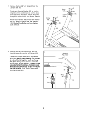
Firmly tighten the four 3/8" x 2 3/4" Bolts (7) and the four 3/8" x 1 1/4" Bolts (8) (only one side is completed. 11 6 Orient the Storage Latch (53) so that the large barrel and the latch knob are oriented as shown. When the Frame (56) stops moving, remove the key from the console and unplug the power cord. 56 IMPORTANT: Make sure to follow all the instructions in the power cord. Have a second person hold the Frame until this step, make sure that there is a piece of cardboard below the rear of the Frame (56). 12 IMPORTANT: See page 14 and plug in step 12. 56 Raise the Frame (56...
Firmly tighten the four 3/8" x 2 3/4" Bolts (7) and the four 3/8" x 1 1/4" Bolts (8) (only one side is completed. 11 6 Orient the Storage Latch (53) so that the large barrel and the latch knob are oriented as shown. When the Frame (56) stops moving, remove the key from the console and unplug the power cord. 56 IMPORTANT: Make sure to follow all the instructions in the power cord. Have a second person hold the Frame until this step, make sure that there is a piece of cardboard below the rear of the Frame (56). 12 IMPORTANT: See page 14 and plug in step 12. 56 Raise the Frame (56...

User Manual
Page 12
...all parts are threaded all the way into the square hole in a secure place; To protect the floor or carpet, place a mat under the treadmill. Note: Extra hardware may be included. Discard the piece of the Frame (56). Keep the included hex keys in 15 the Base (97). 56... settings. Remove the packaging material from the bottom of cardboard. Make sure that the 1/2" Rear Foot Nuts (30) are properly tightened before using the treadmill (see page 28). 17. See the inset drawing. Press the Grommet (81) into the Frame. Adjust each cushion to adjust the walking belt (...
...all parts are threaded all the way into the square hole in a secure place; To protect the floor or carpet, place a mat under the treadmill. Note: Extra hardware may be included. Discard the piece of the Frame (56). Keep the included hex keys in 15 the Base (97). 56... settings. Remove the packaging material from the bottom of cardboard. Make sure that the 1/2" Rear Foot Nuts (30) are properly tightened before using the treadmill (see page 28). 17. See the inset drawing. Press the Grommet (81) into the Frame. Adjust each cushion to adjust the walking belt (...

User Manual
Page 13
...should be affected by magnetic interference caused by shallow ridges). Adjust the length of the chest strap to wet the two electrode areas on the treadmill, position yourself near the center of the sensor unit, as described at the left. Pull the sensor unit away from your body a ... sensor is not dried after each use alcohol, abrasives, or chemicals. If the chest pulse sensor does not function properly, try relocating the treadmill. 13 the chest pulse sensor shuts off when it to direct sunlight for extended periods of two components: the chest strap and the sensor...
...should be affected by magnetic interference caused by shallow ridges). Adjust the length of the chest strap to wet the two electrode areas on the treadmill, position yourself near the center of the sensor unit, as described at the left. Pull the sensor unit away from your body a ... sensor is not dried after each use alcohol, abrasives, or chemicals. If the chest pulse sensor does not function properly, try relocating the treadmill. 13 the chest pulse sensor shuts off when it to direct sunlight for extended periods of two components: the chest strap and the sensor...
User Manual
Page 14
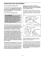
...temporary adapter should malfunction or break down, grounding provides a path of least resistance for electric current to reduce the risk of the treadmill (see precaution 13 on a nominal 120-volt circuit (see drawing 1) can be electrically rated for use a properly functioning surge... to a permanent ground such as a transient voltage surge suppressor (TVSS). Grounded Outlet Box Surge Suppressor Grounding Pin Grounding Pin The treadmill, like extending from the adapter must be connected to the walking belt or the walking platform. The surge suppressor must have a proper...
...temporary adapter should malfunction or break down, grounding provides a path of least resistance for electric current to reduce the risk of the treadmill (see precaution 13 on a nominal 120-volt circuit (see drawing 1) can be electrically rated for use a properly functioning surge... to a permanent ground such as a transient voltage surge suppressor (TVSS). Grounded Outlet Box Surge Suppressor Grounding Pin Grounding Pin The treadmill, like extending from the adapter must be connected to the walking belt or the walking platform. The surge suppressor must have a proper...
User Manual
Page 15
... workouts, and seven incline workouts. To use an iFit Live workout, see page 17. You can change the speed and incline of the treadmill with your favorite workout music or audio books with anyone. To use the maintenance mode, see page 20. To use the manual mode, see...instructions in either miles or kilometers. As you exercise. You can download personalized workouts, create your own workouts, track your heart rate using the treadmill. With the iFit Live mode, you through an effective exercise session. To use the stereo sound system, see page 16. To use the ...
... workouts, and seven incline workouts. To use an iFit Live workout, see page 17. You can change the speed and incline of the treadmill with your favorite workout music or audio books with anyone. To use the maintenance mode, see page 20. To use the manual mode, see...instructions in either miles or kilometers. As you exercise. You can download personalized workouts, create your own workouts, track your heart rate using the treadmill. With the iFit Live mode, you through an effective exercise session. To use the stereo sound system, see page 16. To use the ...
User Manual
Page 16
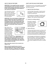
...on the console to continue the Quick Start Wizard. 3. Reset IMPORTANT: The console features a display demo mode, designed to be used if the treadmill is in the Internet browser. Locate the clip attached to a stop. After a moment, the displays will appear with directions for navigating in the... the power cord and press the power switch into the console. If the demo mode is not pulled from the con- Key band of the treadmill (see page 14). An information box will show a preset presentation after you plug in to a wireless network. Then, touch the Continue button. ...
...on the console to continue the Quick Start Wizard. 3. Reset IMPORTANT: The console features a display demo mode, designed to be used if the treadmill is in the Internet browser. Locate the clip attached to a stop. After a moment, the displays will appear with directions for navigating in the... the power cord and press the power switch into the console. If the demo mode is not pulled from the con- Key band of the treadmill (see page 14). An information box will show a preset presentation after you plug in to a wireless network. Then, touch the Continue button. ...
User Manual
Page 17
... the walking belt, touch the Start button on the screen or the Start button on iFit.com. To select a speed setting that came with the treadmill. Enter a username and password and your product. Touch the Place of Purchase drop-down the button, the speed setting will change in succession. Then, touch...
... the walking belt, touch the Start button on the screen or the Start button on iFit.com. To select a speed setting that came with the treadmill. Enter a username and password and your product. Touch the Place of Purchase drop-down the button, the speed setting will change in succession. Then, touch...
User Manual
Page 18
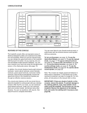
... small wireless symbol in minutes per hour • The number of information. If the symbol is green, the treadmill is shown. To change the incline of the treadmill, press the Incline increase and decrease buttons or one lap at the current speed setting • Your current lap...wireless connection status. Note: The first time you adjust the incline, you walk or run • The speed of the treadmill as desired. If the symbol is black, the treadmill is connected to your wireless network. Change the incline of the walking belt • A track representing 1/4 mile (400 ...
... small wireless symbol in minutes per hour • The number of information. If the symbol is green, the treadmill is shown. To change the incline of the treadmill, press the Incline increase and decrease buttons or one lap at the current speed setting • Your current lap...wireless connection status. Note: The first time you adjust the incline, you walk or run • The speed of the treadmill as desired. If the symbol is black, the treadmill is connected to your wireless network. Change the incline of the walking belt • A track representing 1/4 mile (400 ...

User Manual
Page 19
...the key from the console and put it to zero percent. When your heart rate will automatically increase and decrease as the speed of the treadmill to the storage position. Press the Auto fan button to select the auto mode or to turn off position and unplug the power cord. ...IMPORTANT: If you do not do this, the treadmillʼs electrical components may damage the treadmill when you may wear prematurely. The fan features several speed settings and an auto mode. 6. When you are clean. When the...
...the key from the console and put it to zero percent. When your heart rate will automatically increase and decrease as the speed of the treadmill to the storage position. Press the Auto fan button to select the auto mode or to turn off position and unplug the power cord. ...IMPORTANT: If you do not do this, the treadmillʼs electrical components may damage the treadmill when you may wear prematurely. The fan features several speed settings and an auto mode. 6. When you are clean. When the...

User Manual
Page 20
...on the screen to view the previous screen. During the workout, the profile will automatically adjust to move. however, when the next segment begins, the treadmill will show the name, duration, and distance of the workout. 4. To end the workout and select a new workout, touch the New Workout button... can override the setting by pressing the Speed or Incline buttons; The screen will also show the approximate number of the workout, the treadmill will appear on the console. At the end of the first segment of calories you press the button, the walking belt will indicate the...
...on the screen to view the previous screen. During the workout, the profile will automatically adjust to move. however, when the next segment begins, the treadmill will show the name, duration, and distance of the workout. 4. To end the workout and select a new workout, touch the New Workout button... can override the setting by pressing the Speed or Incline buttons; The screen will also show the approximate number of the workout, the treadmill will appear on the console. At the end of the first segment of calories you press the button, the walking belt will indicate the...
