

User Manual
Page 2
... PRECAUTIONS 3 BEFORE YOU BEGIN 5 ASSEMBLY 6 HOW TO USE THE CHEST PULSE SENSOR 13 OPERATION AND ADJUSTMENT 14 HOW TO FOLD AND MOVE THE TREADMILL 29 TROUBLESHOOTING 30 EXERCISE GUIDELINES 33 PART LIST 34 EXPLODED DRAWING 36 ORDERING REPLACEMENT PARTS Back Cover LIMITED WARRANTY Back Cover WARNING DECAL PLACEMENT This drawing shows the locations of ICON IP, Inc. 2 Note: The decals may not be shown at actual size. NordicTrack is missing or illegible, call...
... PRECAUTIONS 3 BEFORE YOU BEGIN 5 ASSEMBLY 6 HOW TO USE THE CHEST PULSE SENSOR 13 OPERATION AND ADJUSTMENT 14 HOW TO FOLD AND MOVE THE TREADMILL 29 TROUBLESHOOTING 30 EXERCISE GUIDELINES 33 PART LIST 34 EXPLODED DRAWING 36 ORDERING REPLACEMENT PARTS Back Cover LIMITED WARRANTY Back Cover WARNING DECAL PLACEMENT This drawing shows the locations of ICON IP, Inc. 2 Note: The decals may not be shown at actual size. NordicTrack is missing or illegible, call...
User Manual
Page 3
.... The pulse sensor is not working properly. (See TROUBLESHOOTING on the treadmill at a time. 10. Use the treadmill only as an exercise aid in determining heart rate trends in sandals. 11. No other appliance should be on the front cover of high speeds. Do not operate the treadmill where aerosol products are standing on page 16). 17. Never move the walking belt while the power is not...
.... The pulse sensor is not working properly. (See TROUBLESHOOTING on the treadmill at a time. 10. Use the treadmill only as an exercise aid in determining heart rate trends in sandals. 11. No other appliance should be on the front cover of high speeds. Do not operate the treadmill where aerosol products are standing on page 16). 17. Never move the walking belt while the power is not...
User Manual
Page 5
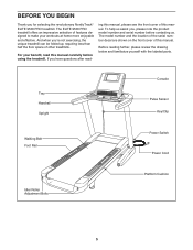
... questions after read this manual carefully before contacting us assist you for selecting the revolutionary NordicTrack® ELITE 9500 PRO treadmill. Before reading further, please review the drawing below and familiarize yourself with the labeled parts. The ELITE 9500 PRO treadmill offers an impressive selection of other treadmills. For your workouts at home more enjoyable and effective. Tray Handrail Upright Console Pulse Sensor Key/Clip Walking Belt Foot Rail Power Switch Power Cord Idler Roller Adjustment Bolts Platform Cushion 5
... questions after read this manual carefully before contacting us assist you for selecting the revolutionary NordicTrack® ELITE 9500 PRO treadmill. Before reading further, please review the drawing below and familiarize yourself with the labeled parts. The ELITE 9500 PRO treadmill offers an impressive selection of other treadmills. For your workouts at home more enjoyable and effective. Tray Handrail Upright Console Pulse Sensor Key/Clip Walking Belt Foot Rail Power Switch Power Cord Idler Roller Adjustment Bolts Platform Cushion 5
User Manual
Page 6
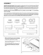
... parts, do not use power tools for assembly. Extra hardware may have been preassembled. The number after the parentheses is unplugged. If there is the key number of the part, from the PART LIST near the end of the walking belt, simply wipe off the lubricant with a soft cloth and a mild, non-abrasive cleaner. The number in a cleared area and remove all packing materials. Set the treadmill...
... parts, do not use power tools for assembly. Extra hardware may have been preassembled. The number after the parentheses is unplugged. If there is the key number of the part, from the PART LIST near the end of the walking belt, simply wipe off the lubricant with a soft cloth and a mild, non-abrasive cleaner. The number in a cleared area and remove all packing materials. Set the treadmill...
User Manual
Page 10
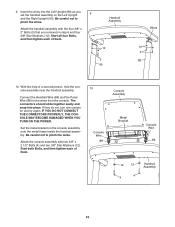
... the wires from the console. Start all four Bolts, and then tighten each of them . Handrail Assembly 12 3 90 Wires 12 3 89 10. Connect the Handrail Wire (86) and the Pulse Wire (88) to pinch the wires. Set the metal bracket on the Left Upright 9 and the Right Upright (90). 9. Insert the wires into place. Attach the console assembly with the four 3/8" x 2" Bolts (3) that you set the handrail assembly on the console assembly onto...
... the wires from the console. Start all four Bolts, and then tighten each of them . Handrail Assembly 12 3 90 Wires 12 3 89 10. Connect the Handrail Wire (86) and the Pulse Wire (88) to pinch the wires. Set the metal bracket on the Left Upright 9 and the Right Upright (90). 9. Insert the wires into place. Attach the console assembly with the four 3/8" x 2" Bolts (3) that you set the handrail assembly on the console assembly onto...

User Manual
Page 13
... have normal heart rhythms. Heart rate reading problems may trap moisture. • Do not expose the chest pulse sensor to direct sunlight for extended periods of the chest strap to wet the two electrode areas on your chest and attach the other container that you walk or run on the chest strap. the chest pulse sensor shuts off when it slightly lower or higher on the sensor unit. Sensor Unit Sensor Unit...
... have normal heart rhythms. Heart rate reading problems may trap moisture. • Do not expose the chest pulse sensor to direct sunlight for extended periods of the chest strap to wet the two electrode areas on your chest and attach the other container that you walk or run on the chest strap. the chest pulse sensor shuts off when it slightly lower or higher on the sensor unit. Sensor Unit Sensor Unit...
User Manual
Page 14
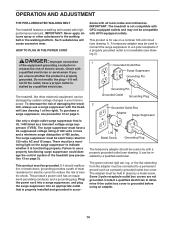
... connected to the walking belt or the walking platform. If it is UL 1449 listed as a properly grounded outlet box cover. This productʼs power cord has an equipment-grounding conductor and a grounding plug. The green-colored rigid ear, lug, or the like other substances to a permanent ground such as a transient voltage surge suppressor (TVSS). The adapter must be electrically rated...
... connected to the walking belt or the walking platform. If it is UL 1449 listed as a properly grounded outlet box cover. This productʼs power cord has an equipment-grounding conductor and a grounding plug. The green-colored rigid ear, lug, or the like other substances to a permanent ground such as a transient voltage surge suppressor (TVSS). The adapter must be electrically rated...
User Manual
Page 15
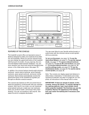
... while using the handgrip pulse sensor or the chest pulse sensor (see page 21. When you use an iFit Live workout, see page 13). CONSOLE DIAGRAM FEATURES OF THE CONSOLE The treadmill console offers an impressive array of plastic on the console, remove the plastic. See www.iFit.com for complete information. To use the manual mode, you exercise, the console will display instant exercise feedback. Each workout automatically controls the speed and incline of the walking belt, and center the walking belt...
... while using the handgrip pulse sensor or the chest pulse sensor (see page 21. When you use an iFit Live workout, see page 13). CONSOLE DIAGRAM FEATURES OF THE CONSOLE The treadmill console offers an impressive array of plastic on the console, remove the plastic. See www.iFit.com for complete information. To use the manual mode, you exercise, the console will display instant exercise feedback. Each workout automatically controls the speed and incline of the walking belt, and center the walking belt...
User Manual
Page 16
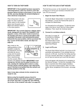
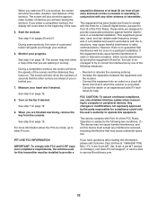
... an emergency, the key can be used if the treadmill is turned on the treadmill, the console will appear. sole, causing the walking belt to slow to a wireless network. An information box will prompt you to set up your wireless connection and your iFit Live account. 1. Connect to a stop. The first time you turn off the demo mode, see step 3 on the treadmill frame near the power cord. Key band of the...
... an emergency, the key can be used if the treadmill is turned on the treadmill, the console will appear. sole, causing the walking belt to slow to a wireless network. An information box will prompt you to set up your wireless connection and your iFit Live account. 1. Connect to a stop. The first time you turn off the demo mode, see step 3 on the treadmill frame near the power cord. Key band of the...
User Manual
Page 17
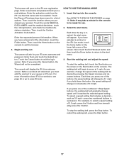
... USE THE MANUAL MODE 1. To start menu. 3. For example, to move at 1 mph. Begin working out. The console will not be ready for a list of 0.5 mph. Start the walking belt and adjust the speed. Then, touch the Home button on the console. Insert the key into the console. For more information about iFit Live workouts, see page 22 or go to exit the browser. 4. Note: If you press one of the buttons, the speed setting...
... USE THE MANUAL MODE 1. To start menu. 3. For example, to move at 1 mph. Begin working out. The console will not be ready for a list of 0.5 mph. Start the walking belt and adjust the speed. Then, touch the Home button on the console. Insert the key into the console. For more information about iFit Live workouts, see page 22 or go to exit the browser. 4. Note: If you press one of the buttons, the speed setting...
User Manual
Page 18
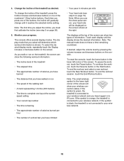
...; Your heart rate (see step 6 on the screen shown at the right. 4. The console offers several display modes. Note: When you select will determine which workout information is connected to your wireless network. 18 The displays at the current speed setting • Your current lap number • The time remaining • The approximate number of calories you have burned • The distance that you use the chest pulse sensor...
...; Your heart rate (see step 6 on the screen shown at the right. 4. The console offers several display modes. Note: When you select will determine which workout information is connected to your wireless network. 18 The displays at the current speed setting • Your current lap number • The time remaining • The approximate number of calories you have burned • The distance that you use the chest pulse sensor...

User Manual
Page 19
... metal contacts for about the chest pulse sensor, see page 13. Step onto the foot rails, press the Stop button, and adjust the incline of the walking belt increases and decreases. When your pulse is selected, the 19 avoid moving your heart rate will be at the same time, the console will automatically increase and decrease as the speed of the treadmill to turn off position and unplug the power cord.
... metal contacts for about the chest pulse sensor, see page 13. Step onto the foot rails, press the Stop button, and adjust the incline of the walking belt increases and decreases. When your pulse is selected, the 19 avoid moving your heart rate will be at the same time, the console will automatically increase and decrease as the speed of the treadmill to turn off position and unplug the power cord.

User Manual
Page 20
... same speed setting and/or incline setting may be programmed for each segment. Touch the Display increase and decrease buttons repeatedly to move. The walking belt will burn during the workout, you will then slow to the speed and incline settings for the next segment. however, when the next segment begins, the treadmill will automatically adjust to a stop and a workout summary will show the approximate number of the workout. 4. To...
... same speed setting and/or incline setting may be programmed for each segment. Touch the Display increase and decrease buttons repeatedly to move. The walking belt will burn during the workout, you will then slow to the speed and incline settings for the next segment. however, when the next segment begins, the treadmill will automatically adjust to a stop and a workout summary will show the approximate number of the workout. 4. To...
User Manual
Page 22
... other runners are designed to operate this equipment. Monitor your heart rate if desired. Turn on page 18. During a competition workout, the screen will show the approximate number of calories you will burn during the workout. For more information about the iFit Live mode, go to provide a If you have run. Start the workout. This equipment has been tested and found to...
... other runners are designed to operate this equipment. Monitor your heart rate if desired. Turn on page 18. During a competition workout, the screen will show the approximate number of calories you will burn during the workout. For more information about the iFit Live mode, go to provide a If you have run. Start the workout. This equipment has been tested and found to...

User Manual
Page 25
... the settings mode. While the demo mode is turned on page 24 for more information about using the keyboard on or turn off the display demo mode, first touch the Demo Mode button. To exit the settings mode, touch the home button on the screen. 25 To view user accounts, touch the iFit Live Login button. See step 2 on , the console will show a preset presentation. The console features a display demo mode, designed to www.iFit.com. 4. When you plug...
... the settings mode. While the demo mode is turned on page 24 for more information about using the keyboard on or turn off the display demo mode, first touch the Demo Mode button. To exit the settings mode, touch the home button on the screen. 25 To view user accounts, touch the iFit Live Login button. See step 2 on , the console will show a preset presentation. The console features a display demo mode, designed to www.iFit.com. 4. When you plug...
User Manual
Page 29
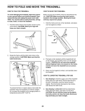
... a wheel. 1 Frame Handrail Frame 2. Then, remove the key and unplug the power cord. CAUTION: Make sure that the latch knob locks. 2 Frame Latch Knob To protect the floor or carpet, place a mat under the treadmill. Moving the treadmill may require two people. 1. Keep the treadmill out of direct sunlight. Pull the latch knob to zero percent before you fold the treadmill. Hold the metal frame firmly with...
... a wheel. 1 Frame Handrail Frame 2. Then, remove the key and unplug the power cord. CAUTION: Make sure that the latch knob locks. 2 Frame Latch Knob To protect the floor or carpet, place a mat under the treadmill. Moving the treadmill may require two people. 1. Keep the treadmill out of direct sunlight. Pull the latch knob to zero percent before you fold the treadmill. Hold the metal frame firmly with...
User Manual
Page 31
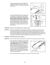
... roller bolts counterclockwise, 1/4 of the Pulley (49). Remove the three #8 x 3/4" Screws (1). The treadmill will recalibrate the incline system. Using the hex key, turn . b 2-3 in . b. Lower the treadmill (see the front cover of the treadmill does not change correctly SOLUTION: a. Carefully pivot the Motor Hood (71) off the walking platform. Reattach the Motor Hood (not shown) with the Reed Switch. PROBLEM: The incline of this manual. 31 If the incline does not calibrate, press the Stop button again, and then press the Incline...
... roller bolts counterclockwise, 1/4 of the Pulley (49). Remove the three #8 x 3/4" Screws (1). The treadmill will recalibrate the incline system. Using the hex key, turn . b 2-3 in . b. Lower the treadmill (see the front cover of the treadmill does not change correctly SOLUTION: a. Carefully pivot the Motor Hood (71) off the walking platform. Reattach the Motor Hood (not shown) with the Reed Switch. PROBLEM: The incline of this manual. 31 If the incline does not calibrate, press the Stop button again, and then press the Incline...
User Manual
Page 34
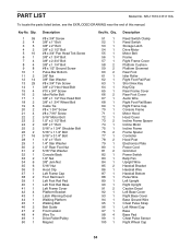
... 1 100 1 Description Reed Switch Clamp Reed Switch Storage Latch Drive Motor Motor Belt Frame Right Frame Cover Platform Cushion Platform Grommet Rear Foot Idler Roller Right Foot Rail Pad Short Hex Key Key/Clip Rear Frame Cover Rear Foot Cover Audio Wire Right Foot Rail Base Right Frame Cap Console Frame Motor Hood Hood Cover Incline Frame Spacer Incline Motor Incline Frame Frame Spacer Controller Hood Post Electronics Plate Power Cord Grommet Power Switch Belly Pan Upright Wire Handrail Bracket Handrail Wire Handrail Bottom Pulse Wire Left Upright Right Upright Caution Decal Left...
... 1 100 1 Description Reed Switch Clamp Reed Switch Storage Latch Drive Motor Motor Belt Frame Right Frame Cover Platform Cushion Platform Grommet Rear Foot Idler Roller Right Foot Rail Pad Short Hex Key Key/Clip Rear Frame Cover Rear Foot Cover Audio Wire Right Foot Rail Base Right Frame Cap Console Frame Motor Hood Hood Cover Incline Frame Spacer Incline Motor Incline Frame Frame Spacer Controller Hood Post Electronics Plate Power Cord Grommet Power Switch Belly Pan Upright Wire Handrail Bracket Handrail Wire Handrail Bottom Pulse Wire Left Upright Right Upright Caution Decal Left...

User Manual
Page 35
Description 101 2 102 1 103 1 104 2 105 2 106 1 Wheel Handrail Top Console Cushion Adjust Assembly #1 Cushion Adjust Assembly #2 Hex Key 107 1 108 1 109 1 110 2 111 2 * - Handrail Frame Pulse Bar Top Pulse Ground Wire Front Cushion 5/16" Cushion Washer Userʼs Manual Note: Specifications are not illustrated. 35 Qty. Key No. Qty. Description Key No. For information about ordering replacement parts, see the back cover of this manual. *These parts are subject to change without notice.
Description 101 2 102 1 103 1 104 2 105 2 106 1 Wheel Handrail Top Console Cushion Adjust Assembly #1 Cushion Adjust Assembly #2 Hex Key 107 1 108 1 109 1 110 2 111 2 * - Handrail Frame Pulse Bar Top Pulse Ground Wire Front Cushion 5/16" Cushion Washer Userʼs Manual Note: Specifications are not illustrated. 35 Qty. Key No. Qty. Description Key No. For information about ordering replacement parts, see the back cover of this manual. *These parts are subject to change without notice.
User Manual
Page 40
..., drive motor, and walking platform are limited in USA © 2010 ICON IP, Inc. ICONʼs obligation under normal use or performance of the product; ORDERING REPLACEMENT PARTS To order replacement parts, please see the PART LIST and the EXPLODED DRAWING near the end of this manual) LIMITED WARRANTY IMPORTANT: You must be responsible for five (5) years from the date of purchase. damages with the use and service...
..., drive motor, and walking platform are limited in USA © 2010 ICON IP, Inc. ICONʼs obligation under normal use or performance of the product; ORDERING REPLACEMENT PARTS To order replacement parts, please see the PART LIST and the EXPLODED DRAWING near the end of this manual) LIMITED WARRANTY IMPORTANT: You must be responsible for five (5) years from the date of purchase. damages with the use and service...


