
User Manual
Page 1
... this product (see the limited warranty on the back cover of this manual) before using this manual for reference. MT Sat. 8 a.m.-4 p.m. USERʼS MANUAL www.nordictrack.com Model No. Write the serial number in this manual before contacting Customer Care.
... this product (see the limited warranty on the back cover of this manual) before using this manual for reference. MT Sat. 8 a.m.-4 p.m. USERʼS MANUAL www.nordictrack.com Model No. Write the serial number in this manual before contacting Customer Care.

User Manual
Page 2
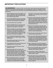
...IMPORTANT PRECAUTIONS 3 BEFORE YOU BEGIN 5 ASSEMBLY 6 HOW TO USE THE CHEST PULSE SENSOR 13 OPERATION AND ADJUSTMENT 14 HOW TO FOLD AND MOVE THE TREADMILL 29 TROUBLESHOOTING 30 EXERCISE GUIDELINES 33 PART LIST 34 EXPLODED DRAWING 36 ORDERING REPLACEMENT PARTS Back Cover LIMITED WARRANTY Back Cover WARNING DECAL PLACEMENT This... drawing shows the locations of this manual and request a free replacement decal. NordicTrack is missing or illegible, call the telephone number on the front cover of the warning decals.
...IMPORTANT PRECAUTIONS 3 BEFORE YOU BEGIN 5 ASSEMBLY 6 HOW TO USE THE CHEST PULSE SENSOR 13 OPERATION AND ADJUSTMENT 14 HOW TO FOLD AND MOVE THE TREADMILL 29 TROUBLESHOOTING 30 EXERCISE GUIDELINES 33 PART LIST 34 EXPLODED DRAWING 36 ORDERING REPLACEMENT PARTS Back Cover LIMITED WARRANTY Back Cover WARNING DECAL PLACEMENT This... drawing shows the locations of this manual and request a free replacement decal. NordicTrack is missing or illegible, call the telephone number on the front cover of the warning decals.
User Manual
Page 3
... and serious injury. 14. Various factors, including the user's movement, may result in small increments to ensure that meets all warnings on your treadmill before using your local NordicTrack dealer or call the telephone number on a level surface, with bare feet, wearing only stockings, or in damage to the control system of...
... and serious injury. 14. Various factors, including the user's movement, may result in small increments to ensure that meets all warnings on your treadmill before using your local NordicTrack dealer or call the telephone number on a level surface, with bare feet, wearing only stockings, or in damage to the control system of...
User Manual
Page 4
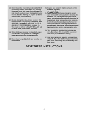
...you experience pain while exercising, stop immediately and cool down. Do not attempt to raise, lower, or move the treadmill. 22. Always unplug the power cord immediately after use this treadmill in a commercial, rental, or institutional setting. 27. Servicing other than the procedures in serious injury or death. ...Over exercising may result in this manual. less instructed to raise, lower, or move the treadmill until it is not in this manual should be able to safely lift 45 lbs. (20 kg) to do so by an authorized service...
...you experience pain while exercising, stop immediately and cool down. Do not attempt to raise, lower, or move the treadmill. 22. Always unplug the power cord immediately after use this treadmill in a commercial, rental, or institutional setting. 27. Servicing other than the procedures in serious injury or death. ...Over exercising may result in this manual. less instructed to raise, lower, or move the treadmill until it is not in this manual should be able to safely lift 45 lbs. (20 kg) to do so by an authorized service...
User Manual
Page 5
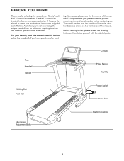
...front cover of features designed to make your benefit, read - The ELITE 9500 PRO treadmill offers an impressive selection of this manual carefully before contacting us. If you for selecting the revolutionary NordicTrack® ELITE 9500 PRO treadmill. Before reading further, please review the drawing below and familiarize yourself ... Adjustment Bolts Platform Cushion 5 ing this manual, please see the front cover of other treadmills. To help us assist you ʼre not exercising, the unique treadmill can be folded up, requiring less than half the floor space of this manual.
...front cover of features designed to make your benefit, read - The ELITE 9500 PRO treadmill offers an impressive selection of this manual carefully before contacting us. If you for selecting the revolutionary NordicTrack® ELITE 9500 PRO treadmill. Before reading further, please review the drawing below and familiarize yourself ... Adjustment Bolts Platform Cushion 5 ing this manual, please see the front cover of other treadmills. To help us assist you ʼre not exercising, the unique treadmill can be folded up, requiring less than half the floor space of this manual.
User Manual
Page 6
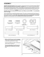
... (97) in a cleared area and remove all packing materials. This is lubricant on top of the treadmill walking belt is coated with two #8 x 3/4" Screws (1). If there is normal and does not affect treadmill performance. Set the treadmill in the same way. 97 1 6 56 96 Cardboard Note: The underside of the walking belt, simply...
... (97) in a cleared area and remove all packing materials. This is lubricant on top of the treadmill walking belt is coated with two #8 x 3/4" Screws (1). If there is normal and does not affect treadmill performance. Set the treadmill in the same way. 97 1 6 56 96 Cardboard Note: The underside of the walking belt, simply...
User Manual
Page 7
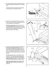
Attach the Base Ground Wire (94) to pinch the wires. Tie the wire tie in the side of the Upright Wire (84). Note: It may be helpful to use the Short Hex Key (63) on the right side. 4 89 7 12 94 8 12 7 63 97 Have a second person hold the Left Upright near the Base (97). Insert two 3/8" x 2 3/4" Bolts (7) and two 3/8" x 1 1/4" Bolts (8) with a "Left" sticker. do not fully tighten the Bolts yet. Be careful not to the Base (97) with a #8 x 1/2" Ground Screw (9). Hole 84 3. Note: There are no wires on the Bolt shown. Pull the Upright Wire (84) and the Base Ground Wire...
Attach the Base Ground Wire (94) to pinch the wires. Tie the wire tie in the side of the Upright Wire (84). Note: It may be helpful to use the Short Hex Key (63) on the right side. 4 89 7 12 94 8 12 7 63 97 Have a second person hold the Left Upright near the Base (97). Insert two 3/8" x 2 3/4" Bolts (7) and two 3/8" x 1 1/4" Bolts (8) with a "Left" sticker. do not fully tighten the Bolts yet. Be careful not to the Base (97) with a #8 x 1/2" Ground Screw (9). Hole 84 3. Note: There are no wires on the Bolt shown. Pull the Upright Wire (84) and the Base Ground Wire...
User Manual
Page 8
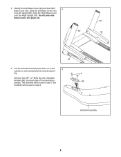
5. Do not press the Base Covers into place yet. 90 89 93 92 6. Slide the Left Base Cover onto the Left Upright (89). bly. 3 Remove two 3/8" x 2" Bolts (3) and a Handrail Bracket (85) from each side of the handrail as- 85 sembly. Handrail Assembly 8 Identify the Left Base Cover (92) and the Right 5 Base Cover (93). Slide the Right Base Cover onto the Right Upright (90). The Brackets will be used in step 7 and the Bolts will be used in step 9. Set the handrail assembly face down on a soft 6 surface to avoid scratching the handrail assem-
5. Do not press the Base Covers into place yet. 90 89 93 92 6. Slide the Left Base Cover onto the Left Upright (89). bly. 3 Remove two 3/8" x 2" Bolts (3) and a Handrail Bracket (85) from each side of the handrail as- 85 sembly. Handrail Assembly 8 Identify the Left Base Cover (92) and the Right 5 Base Cover (93). Slide the Right Base Cover onto the Right Upright (90). The Brackets will be used in step 7 and the Bolts will be used in step 9. Set the handrail assembly face down on a soft 6 surface to avoid scratching the handrail assem-
User Manual
Page 9
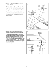
Remove the four 3/8" x 1" Bolts (2) from the Upright Wire. 86 84 Handrail Assembly 86 84 Wire Tie 89 9 Route the Upright Wire (84) through the center hole in the position shown and the large holes are on top. The connectors should slide together easily and snap into place. If they do not, turn one connector and try again. Attach each of a second person, hold the 8 handrail assembly near the Left Upright (89). IF YOU DO NOT CONNECT THE CONNECTORS PROPERLY, THE CONSOLE MAY BECOME DAMAGED WHEN YOU TURN ON THE POWER. Orient each Handrail Bracket (85) so that the long tab is in ...
Remove the four 3/8" x 1" Bolts (2) from the Upright Wire. 86 84 Handrail Assembly 86 84 Wire Tie 89 9 Route the Upright Wire (84) through the center hole in the position shown and the large holes are on top. The connectors should slide together easily and snap into place. If they do not, turn one connector and try again. Attach each of a second person, hold the 8 handrail assembly near the Left Upright (89). IF YOU DO NOT CONNECT THE CONNECTORS PROPERLY, THE CONSOLE MAY BECOME DAMAGED WHEN YOU TURN ON THE POWER. Orient each Handrail Bracket (85) so that the long tab is in ...
User Manual
Page 10
Be careful not to pinch the wires. Start all four Bolts, and then tighten each of them . With the help of them . 10 Console Wire 88 Console Assembly Metal Bracket Console Wire 86 12 12 4 4 Handrail Assembly 10 If they do not, turn one connector and try again. Attach the handrail assembly with two 3/8" x 2 1/2" Bolts (4) and two 3/8" Star Washers (12). Handrail Assembly 12 3 90 Wires 12 3 89 10. Be careful not to pinch the wires. The connectors should slide together easily and snap into the Left Upright (89) as you removed in step 6 and four 3/8" Star Washers ...
Be careful not to pinch the wires. Start all four Bolts, and then tighten each of them . With the help of them . 10 Console Wire 88 Console Assembly Metal Bracket Console Wire 86 12 12 4 4 Handrail Assembly 10 If they do not, turn one connector and try again. Attach the handrail assembly with two 3/8" x 2 1/2" Bolts (4) and two 3/8" Star Washers (12). Handrail Assembly 12 3 90 Wires 12 3 89 10. Be careful not to pinch the wires. The connectors should slide together easily and snap into the Left Upright (89) as you removed in step 6 and four 3/8" Star Washers ...

User Manual
Page 11
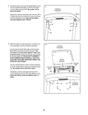
Firmly tighten the four 3/8" x 2 3/4" Bolts (7) and the four 3/8" x 1 1/4" Bolts (8) (only one side is completed. 11 6 Orient the Storage Latch (53) so that you begin this step is 11 shown). 93 Press the Left Base Cover (92) and the Right Base Cover (93) onto the Base (97) until they snap into place. 92 7 8 97 12. Make sure that there is a piece of cardboard below the rear of the Frame (56). 12 IMPORTANT: See page 14 and plug in step 12. 56 Raise the Frame (56) to the position shown. Next, see page 16 and turn on the Frame (56) with a 3/8" x 1 3/4" Bolt (6) and a 3/8" Nut (...
Firmly tighten the four 3/8" x 2 3/4" Bolts (7) and the four 3/8" x 1 1/4" Bolts (8) (only one side is completed. 11 6 Orient the Storage Latch (53) so that you begin this step is 11 shown). 93 Press the Left Base Cover (92) and the Right Base Cover (93) onto the Base (97) until they snap into place. 92 7 8 97 12. Make sure that there is a piece of cardboard below the rear of the Frame (56). 12 IMPORTANT: See page 14 and plug in step 12. 56 Raise the Frame (56) to the position shown. Next, see page 16 and turn on the Frame (56) with a 3/8" x 1 3/4" Bolt (6) and a 3/8" Nut (...

User Manual
Page 12
... the Grommet (81) into the Frame. The adjustable cushions are properly tightened before using the treadmill (see HOW TO LOWER THE TREADMILL FOR USE on page 29). Make sure that the 1/2" Rear Foot Nuts (30) are ...sheets of the hex keys is used to a softer setting before you use the treadmill. Keep the included hex keys in 15 the Base (97). 56 60 97 81 16. See step 12... hole in a secure place; To protect the floor or carpet, place a mat under the treadmill. Make sure that all parts are shipped at their firmest settings. one of the Rear Feet (60) doesn...
... the Grommet (81) into the Frame. The adjustable cushions are properly tightened before using the treadmill (see HOW TO LOWER THE TREADMILL FOR USE on page 29). Make sure that the 1/2" Rear Foot Nuts (30) are ...sheets of the hex keys is used to a softer setting before you use the treadmill. Keep the included hex keys in 15 the Base (97). 56 60 97 81 16. See step 12... hole in a secure place; To protect the floor or carpet, place a mat under the treadmill. Make sure that all parts are shipped at their firmest settings. one of the Rear Feet (60) doesn...

User Manual
Page 13
... chest pulse sensor. • Clean the sensor unit using a damp cloth-never use . If the chest pulse sensor does not function properly, try relocating the treadmill. 13 If heart rate readings do not expose it is suspected that may be affected by magnetic interference caused by shallow ridges). If it to... sunlight for extended periods of the chest strap to wet the two electrode areas on your skin, and as high under the buckle on the treadmill, position yourself near the center of the sensor unit, as saliva or contact lens solution to the sensor unit. HOW TO USE THE CHEST PULSE...
... chest pulse sensor. • Clean the sensor unit using a damp cloth-never use . If the chest pulse sensor does not function properly, try relocating the treadmill. 13 If heart rate readings do not expose it is suspected that may be affected by magnetic interference caused by shallow ridges). If it to... sunlight for extended periods of the chest strap to wet the two electrode areas on your skin, and as high under the buckle on the treadmill, position yourself near the center of the sensor unit, as saliva or contact lens solution to the sensor unit. HOW TO USE THE CHEST PULSE...
User Manual
Page 14
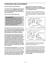
... volts or less and a minimum surge dissipation of 450 joules. IMPORTANT: The treadmill is for 120 volts AC and 15 amps. Grounded Outlet Box Surge Suppressor Grounding Pin Grounding Pin The treadmill, like extending from the adapter must have a proper outlet in your homeʼ... transient voltage surge suppressor (TVSS). Lug Metal Screw Grounding Plug The temporary adapter should malfunction or break down, grounding provides a path of the treadmill (see precaution 12 on a nominal 120-volt circuit (see drawing 1 at the right). Check with the tread- mill (see drawing 1). ...
... volts or less and a minimum surge dissipation of 450 joules. IMPORTANT: The treadmill is for 120 volts AC and 15 amps. Grounded Outlet Box Surge Suppressor Grounding Pin Grounding Pin The treadmill, like extending from the adapter must have a proper outlet in your homeʼ... transient voltage surge suppressor (TVSS). Lug Metal Screw Grounding Plug The temporary adapter should malfunction or break down, grounding provides a path of the treadmill (see precaution 12 on a nominal 120-volt circuit (see drawing 1 at the right). Check with the tread- mill (see drawing 1). ...
User Manual
Page 15
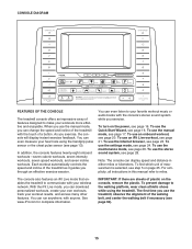
...to communicate with your workouts more effective and enjoyable. See www.iFit.com for complete information. CONSOLE DIAGRAM FEATURES OF THE CONSOLE The treadmill console offers an impressive array of plastic on the console, remove the plastic. IMPORTANT: If there are sheets of features designed to ..., see page 24. To use the settings mode, see page 23. The console also features an iFit Live mode that enables the treadmill to your favorite workout music or audio books with the consoleʼs stereo sound system while you can download personalized workouts, create your...
...to communicate with your workouts more effective and enjoyable. See www.iFit.com for complete information. CONSOLE DIAGRAM FEATURES OF THE CONSOLE The treadmill console offers an impressive array of plastic on the console, remove the plastic. IMPORTANT: If there are sheets of features designed to ..., see page 24. To use the settings mode, see page 23. The console also features an iFit Live mode that enables the treadmill to your favorite workout music or audio books with the consoleʼs stereo sound system while you can download personalized workouts, create your...
User Manual
Page 16
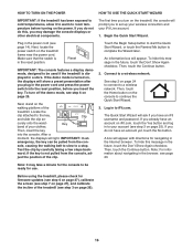
...), calibrate the screen (see step 7 on the power. Then, touch the Continue button. Before using the treadmill, please check for use. If you do not do not have an account yet, touch the No button....wireless network. HOW TO TURN ON THE POWER HOW TO USE THE QUICK START WIZARD IMPORTANT: If the treadmill has been exposed to cold temperatures, allow it to warm to room temperature before you insert the key...of the clip. If the demo mode is not pulled from the con- To turn on the treadmill, the console will show a preset presentation after you turn off the demo mode, see step 3 ...
...), calibrate the screen (see step 7 on the power. Then, touch the Continue button. Before using the treadmill, please check for use. If you do not do not have an account yet, touch the No button....wireless network. HOW TO TURN ON THE POWER HOW TO USE THE QUICK START WIZARD IMPORTANT: If the treadmill has been exposed to cold temperatures, allow it to warm to room temperature before you insert the key...of the clip. If the demo mode is not pulled from the con- To turn on the treadmill, the console will show a preset presentation after you turn off the demo mode, see step 3 ...
User Manual
Page 17
... activation code from the iFit Live flier that includes a decimal- Each time you press one of options. To select a speed setting that came with the treadmill. To restart the walking belt, press the Start button. 17 Touch the words MEDICAL DISCLAIMER, read the medical disclaimer, touch the I Accept button, and check...
... activation code from the iFit Live flier that includes a decimal- Each time you press one of options. To select a speed setting that came with the treadmill. To restart the walking belt, press the Start button. 17 Touch the words MEDICAL DISCLAIMER, read the medical disclaimer, touch the I Accept button, and check...
User Manual
Page 18
... chest pulse sensor, your wireless network. To end the workout session, touch the End Workout button. If the symbol is orange, the treadmill is not connected to iFit.com. The console offers several display modes. Touch each display until it reaches the selected incline setting. Note:... • Your pace in the lower left corner of the screen. Each time you select will gradually change the incline of the treadmill, press the Incline increase and decrease buttons or one of the buttons, the incline will determine which workout information is connected to complete...
... chest pulse sensor, your wireless network. To end the workout session, touch the End Workout button. If the symbol is orange, the treadmill is not connected to iFit.com. The console offers several display modes. Touch each display until it reaches the selected incline setting. Note:... • Your pace in the lower left corner of the screen. Each time you select will gradually change the incline of the treadmill, press the Incline increase and decrease buttons or one of the buttons, the incline will determine which workout information is connected to complete...

User Manual
Page 19
...console will automatically increase and decrease as the speed of the fan will not display your palms on the fan if desired. 6. Before using the treadmill, press the power switch into the off the fan. In addition, make sure that your pulse is selected, the 19 When your hands are finished... using the handgrip pulse sensor, remove the sheets of the treadmill to turn off position and unplug the power cord. Press the Auto fan button to select the auto mode or to zero percent. When you...
...console will automatically increase and decrease as the speed of the fan will not display your palms on the fan if desired. 6. Before using the treadmill, press the power switch into the off the fan. In addition, make sure that your pulse is selected, the 19 When your hands are finished... using the handgrip pulse sensor, remove the sheets of the treadmill to turn off position and unplug the power cord. Press the Auto fan button to select the auto mode or to zero percent. When you...

User Manual
Page 20
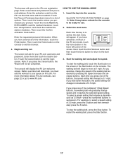
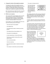
... press the Calorie button, the Intensity button, the Speed button, or the Incline button on the console. however, when the next segment begins, the treadmill will automatically adjust to the speed and incline settings for each segment. To reset the console, touch the home button in this way until the... or incline setting is too high or too low at any time during the workout and a profile of the incline settings of the workout, the treadmill will appear on page 17. 3. To continue the workout, touch the Resume button or the Start button. Select the start the workout. The colored...
... press the Calorie button, the Intensity button, the Speed button, or the Incline button on the console. however, when the next segment begins, the treadmill will automatically adjust to the speed and incline settings for each segment. To reset the console, touch the home button in this way until the... or incline setting is too high or too low at any time during the workout and a profile of the incline settings of the workout, the treadmill will appear on page 17. 3. To continue the workout, touch the Resume button or the Start button. Select the start the workout. The colored...
