
Software Guide
Page 4
S3300 Smart Switch Multiple Stack Links 74 PoE 76 Advanced PoE Configuration 77 Advanced PoE Port Configuration 77 SNMP 80 Configure the SNMPv1/v2 Community 80 LLDP 84 LLDP Configuration 85 LLDP Port Settings 86 LLDP-MED Network Policy 87 ...
S3300 Smart Switch Multiple Stack Links 74 PoE 76 Advanced PoE Configuration 77 Advanced PoE Port Configuration 77 SNMP 80 Configure the SNMPv1/v2 Community 80 LLDP 84 LLDP Configuration 85 LLDP Port Settings 86 LLDP-MED Network Policy 87 ...
Software Guide
Page 9
1. The S3300 switches are : • S3300-28X • S3300-28X-PoE+ • S3300-52X • S3300-52X-PoE+ The information in this document. The individual switches are referred to as the NETGEAR switch throughout this document applies to configure and operate the ProSafe™/® S3300 Smart Switch family by using... the web-based graphical user interface (GUI). Note: For information about issues and workarounds, see the release notes for the NETGEAR switch. 9 The manual describes the ...
1. The S3300 switches are : • S3300-28X • S3300-28X-PoE+ • S3300-52X • S3300-52X-PoE+ The information in this document. The individual switches are referred to as the NETGEAR switch throughout this document applies to configure and operate the ProSafe™/® S3300 Smart Switch family by using... the web-based graphical user interface (GUI). Note: For information about issues and workarounds, see the release notes for the NETGEAR switch. 9 The manual describes the ...
Software Guide
Page 22
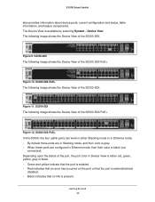
... and status, table information, and feature components. Figure 12. Depending upon the status of the S3300-28X-PoE+. S3300-28X The following image shows the Device View of the S3300-28X. S3300-28X-PoE+ The following image shows the Device View of the port, the port color in Device View is... is administratively disabled. • Black indicates that no link is available by selecting System Device View. Figure 9. S3300-52X-PoE+ In the S3300, the four uplink ports can work in Ethernet mode, then their color is blank (not connected). Getting Started 22 Figure ...
... and status, table information, and feature components. Figure 12. Depending upon the status of the S3300-28X-PoE+. S3300-28X The following image shows the Device View of the S3300-28X. S3300-28X-PoE+ The following image shows the Device View of the port, the port color in Device View is... is administratively disabled. • Black indicates that no link is available by selecting System Device View. Figure 9. S3300-52X-PoE+ In the S3300, the four uplink ports can work in Ethernet mode, then their color is blank (not connected). Getting Started 22 Figure ...
Software Guide
Page 24
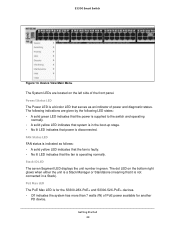
... lit LED indicates that the fan is a bicolor LED that serves as an indicator of power and diagnostic status. S3300 Smart Switch Figure 14. The dot LED on the left side of PoE power available for another PD device. Getting Started 24 The following LED states: • A solid green LED indicates that... the following indications are located on the bottom right glows when either the unit is a Stack Manager or Standalone (meaning that power is for the S3300-28X-PoE+ and S3300-52X-PoE+ devices. • Off indicates the system has more than 7 watts (W) of the front panel...
... lit LED indicates that the fan is a bicolor LED that serves as an indicator of power and diagnostic status. S3300 Smart Switch Figure 14. The dot LED on the left side of PoE power available for another PD device. Getting Started 24 The following LED states: • A solid green LED indicates that... the following indications are located on the bottom right glows when either the unit is a Stack Manager or Standalone (meaning that power is for the S3300-28X-PoE+ and S3300-52X-PoE+ devices. • Off indicates the system has more than 7 watts (W) of the front panel...

Software Guide
Page 25
... Definition Backslash Forward slash Asterisk Question mark Less than Greater than 7W of the Help link on page 20 shows the location of PoE power is open, the help screens are context-sensitive. The online help topic for that feature): Table 2. User-Defined Fields User...the IP Addressing screen is available. • A blinking yellow LED indicates the device was active in the field label on the configuration screen. S3300 Smart Switch • A steady yellow LED indicates that less than Pipe Getting Started 25 Help Access Every screen contains a button to launch online ...
... Definition Backslash Forward slash Asterisk Question mark Less than Greater than 7W of the Help link on page 20 shows the location of PoE power is open, the help screens are context-sensitive. The online help topic for that feature): Table 2. User-Defined Fields User...the IP Addressing screen is available. • A blinking yellow LED indicates the device was active in the field label on the configuration screen. S3300 Smart Switch • A steady yellow LED indicates that less than Pipe Getting Started 25 Help Access Every screen contains a button to launch online ...
Software Guide
Page 27
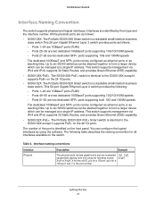
... address. This switch supports management via IPv4 and IPv6, supports 32 Static Routes, and provides Green Ethernet (EEE) capability. • S3300-28X-PoE+. The following table describes the naming convention for a 10G port, and Y is a stackable small/medium business class switch.This 28-...ports (RJ45) - The number of the port is for all interfaces available on the 24 1G ports. • S3300-52X. The S3300-28X-PoE+ switch is a stackable small/medium business class switch. Interface naming conventions Interface Physical Description Example The physical ports include ...
... address. This switch supports management via IPv4 and IPv6, supports 32 Static Routes, and provides Green Ethernet (EEE) capability. • S3300-28X-PoE+. The following table describes the naming convention for a 10G port, and Y is a stackable small/medium business class switch.This 28-...ports (RJ45) - The number of the port is for all interfaces available on the 24 1G ports. • S3300-52X. The S3300-28X-PoE+ switch is a stackable small/medium business class switch. Interface naming conventions Interface Physical Description Example The physical ports include ...

Software Guide
Page 35
Configure System Information 2 Use the features you access from the System navigation tab to define the switch's relationship to the configuration menus described in the following sections: • Management on page 36 • Device View on page 62 • License on page 63 • Switch Stack Configuration on page 64 • PoE on page 76 • SNMP on page 80 • LLDP on page 84 • Services on page 95 • Timer Schedule on page 109 35 The System navigation tab provides access to its environment. 2.
Configure System Information 2 Use the features you access from the System navigation tab to define the switch's relationship to the configuration menus described in the following sections: • Management on page 36 • Device View on page 62 • License on page 63 • Switch Stack Configuration on page 64 • PoE on page 76 • SNMP on page 80 • LLDP on page 84 • Services on page 95 • Timer Schedule on page 109 35 The System navigation tab provides access to its environment. 2.
Software Guide
Page 75
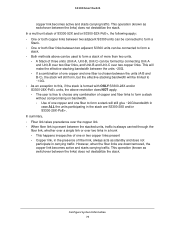
...-A and Unit-B over two fiber links, and Unit-B and Unit-C over two copper links. However, when the fiber links are S3300-28X and/or S3300-28X-PoE+. This operation (known as standby and does not participate in the stack are down/removed, the copper link becomes active and starts ... connected to form a stack. • Both methods above restriction does NOT apply. - A Stack of more than two units. - If a combination of S3300-52X and/or S3300-52X-PoE+, the following apply: • One or both fiber links between the links) does not destabilize the stack. Configure System Information 75...
...-A and Unit-B over two fiber links, and Unit-B and Unit-C over two copper links. However, when the fiber links are S3300-28X and/or S3300-28X-PoE+. This operation (known as standby and does not participate in the stack are down/removed, the copper link becomes active and starts ... connected to form a stack. • Both methods above restriction does NOT apply. - A Stack of more than two units. - If a combination of S3300-52X and/or S3300-52X-PoE+, the following apply: • One or both fiber links between the links) does not destabilize the stack. Configure System Information 75...

Software Guide
Page 76
... the configuration on the port. 5. Click the Cancel button to the requesting PDs. The following table describes the non-configurable PoE Configuration data that is Dynamic. • Static. Possible values are specific to the whole unit, not specific to configure a few system-level... PoE parameters per unit. The data on the type of the PoE controller's FW image. The default mode is displayed. S3300 Smart Switch PoE Use this field. 3. In other words, the parameters are : • Dynamic. ...
... the configuration on the port. 5. Click the Cancel button to the requesting PDs. The following table describes the non-configurable PoE Configuration data that is Dynamic. • Static. Possible values are specific to the whole unit, not specific to configure a few system-level... PoE parameters per unit. The data on the type of the PoE controller's FW image. The default mode is displayed. S3300 Smart Switch PoE Use this field. 3. In other words, the parameters are : • Dynamic. ...

Software Guide
Page 77
... to determine which ports can be between Nominal and Threshold Power values. However the Advanced screen allows you to configure a host of PoE parameters specific to port(s) of power which is not changed accordingly. There could be able to supply power to all ports in showing... configure advanced PoE port settings. 1. The factory default is used to deliver power - Next to Admin Mode, select the Enable button to enable the port to update the page with the latest information on the switch. Priority is Enable. 4. Click Update to deliver a power. S3300 Smart Switch...
... to determine which ports can be between Nominal and Threshold Power values. However the Advanced screen allows you to configure a host of PoE parameters specific to port(s) of power which is not changed accordingly. There could be able to supply power to all ports in showing... configure advanced PoE port settings. 1. The factory default is used to deliver power - Next to Admin Mode, select the Enable button to enable the port to update the page with the latest information on the switch. Priority is Enable. 4. Click Update to deliver a power. S3300 Smart Switch...

Software Guide
Page 79
...The interface for which data is to forcibly reset the PSE port. The temperature is displayed. The following table describes the non-configurable PoE Port Configuration data that can be displayed or configured. Enabled when a particular port supports High Power Mode. The maximum power in milliwatts... the Cancel button to the latest value of the switch. 12. Configure System Information 79 The data on the screen is drawing from the system. S3300 Smart Switch 11. Class definitions are: 0. 0.44-16.2 watts 1. 0.44-4.2 watts 2. 0.44-7.4 watts 3. 0.44-16.2 watts 4. 0.44-31.2 watts ...
...The interface for which data is to forcibly reset the PSE port. The temperature is displayed. The following table describes the non-configurable PoE Port Configuration data that can be displayed or configured. Enabled when a particular port supports High Power Mode. The maximum power in milliwatts... the Cancel button to the latest value of the switch. 12. Configure System Information 79 The data on the screen is drawing from the system. S3300 Smart Switch 11. Class definitions are: 0. 0.44-16.2 watts 1. 0.44-4.2 watts 2. 0.44-7.4 watts 3. 0.44-16.2 watts 4. 0.44-31.2 watts ...

Software Guide
Page 109
...76. • Define a Timer Schedule Name on page 109 • Configure Timer Schedule on the System PoE PoE Port Configuration screen. You can also select System Timer Schedule Advanced > Global Configuration. 2. ...Click the Delete button. S3300 Smart Switch Timer Schedule The NETGEAR Smart Switch provides timer schedules for use Timer Schedules with PoE/PoE+. Configuration changes take effect immediately. The Timer Schedule screen displays. 3. To use with PoE/PoE+, you associate the timer schedule to a PoE/PoE+ port (or ports...
...76. • Define a Timer Schedule Name on page 109 • Configure Timer Schedule on the System PoE PoE Port Configuration screen. You can also select System Timer Schedule Advanced > Global Configuration. 2. ...Click the Delete button. S3300 Smart Switch Timer Schedule The NETGEAR Smart Switch provides timer schedules for use Timer Schedules with PoE/PoE+. Configuration changes take effect immediately. The Timer Schedule screen displays. 3. To use with PoE/PoE+, you associate the timer schedule to a PoE/PoE+ port (or ports...
Software Guide
Page 339
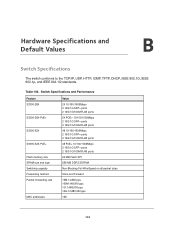
... HTTP, ICMP, TFTP, DHCP, IEEE 802.1D, IEEE 802.1p, and IEEE 802.1Q standards. B. Switch Specifications and Performance Feature S3300-28X S3300-28X-PoE+ S3300-52X S3300-52X-PoE+ Flash memory size SRAM size and type Switching capacity Forwarding method Packet forwarding rate MAC addresses Value 24 10/100/1000Mbps 2 10G/1G ...SFP+ ports 2 10G/1G/100M RJ45 ports 24 POE+ 10/100/1000Mbps 2 10G/1G SFP+ ports 2 10G/1G/100M RJ45 ports 48 ...
... HTTP, ICMP, TFTP, DHCP, IEEE 802.1D, IEEE 802.1p, and IEEE 802.1Q standards. B. Switch Specifications and Performance Feature S3300-28X S3300-28X-PoE+ S3300-52X S3300-52X-PoE+ Flash memory size SRAM size and type Switching capacity Forwarding method Packet forwarding rate MAC addresses Value 24 10/100/1000Mbps 2 10G/1G ...SFP+ ports 2 10G/1G/100M RJ45 ports 24 POE+ 10/100/1000Mbps 2 10G/1G SFP+ ports 2 10G/1G/100M RJ45 ports 48 ...

Software Guide
Page 340
... Switch Priority Stack Sample Mode Stack Port Configured Stack Mode Stack Firmware Synchronization Stack Firmware Auto Upgrade Traps Allow Downgrade PoE Global System Usage Threshold Power Management Mode Traps Interface Default Disabled Disabled Disabled Disabled Disabled Unassigned Cumulative Stack Disabled Enabled Enabled... 95% Dynamic Enabled Hardware Specifications and Default Values 340 Table 103. S3300 Smart Switch Switch Features and Defaults The tables in this section provide information about the switch features and default values.
... Switch Priority Stack Sample Mode Stack Port Configured Stack Mode Stack Firmware Synchronization Stack Firmware Auto Upgrade Traps Allow Downgrade PoE Global System Usage Threshold Power Management Mode Traps Interface Default Disabled Disabled Disabled Disabled Disabled Unassigned Cumulative Stack Disabled Enabled Enabled... 95% Dynamic Enabled Hardware Specifications and Default Values 340 Table 103. S3300 Smart Switch Switch Features and Defaults The tables in this section provide information about the switch features and default values.

