Hardware Installation Guide
Page 1
Managed Switch Hardware Installation Guide Models: M4100 Series 350 East Plumeria Drive San Jose, CA 95134 USA November 2013 202-11217-02 v1.0
Managed Switch Hardware Installation Guide Models: M4100 Series 350 East Plumeria Drive San Jose, CA 95134 USA November 2013 202-11217-02 v1.0
Hardware Installation Guide
Page 2
... names are registered trademarks of Microsoft Corporation. NETGEAR Managed Switch Support Thank you can use it to register your product at http://support.netgear.com/general/contact/default.aspx. NETGEAR recommends registering your product before you for selecting NETGEAR products. Phone (Other Countries): Check the ... are trademarks or registered trademarks of your device, locate the serial number on the label of NETGEAR, Inc. After installing your product and use NETGEAR telephone support. Revision History Publication Part Number 202-11217-01 202-11217-02 Version v1.0 v1...
... names are registered trademarks of Microsoft Corporation. NETGEAR Managed Switch Support Thank you can use it to register your product at http://support.netgear.com/general/contact/default.aspx. NETGEAR recommends registering your product before you for selecting NETGEAR products. Phone (Other Countries): Check the ... are trademarks or registered trademarks of your device, locate the serial number on the label of NETGEAR, Inc. After installing your product and use NETGEAR telephone support. Revision History Publication Part Number 202-11217-01 202-11217-02 Version v1.0 v1...

Hardware Installation Guide
Page 4
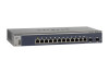
... : M4100-26G M4100-50G M4100-26-POE M4100-26G-POE M4100-50G-POE+ M4100-50-POE M4100-D10-POE M4100-D12G M4100-12GF M4100-D12G-POE+ M4100-24G-POE+ M4100-12G-POE+ This guide describes hardware installation and basic troubleshooting for each product, visit the NETGEAR website at http://www.netgear.com. 1. Introduction 1 The NETGEAR ProSafe® 4100 series managed switches provide state-of the ProSafe 4100 series managed switches. These switches...
... : M4100-26G M4100-50G M4100-26-POE M4100-26G-POE M4100-50G-POE+ M4100-50-POE M4100-D10-POE M4100-D12G M4100-12GF M4100-D12G-POE+ M4100-24G-POE+ M4100-12G-POE+ This guide describes hardware installation and basic troubleshooting for each product, visit the NETGEAR website at http://www.netgear.com. 1. Introduction 1 The NETGEAR ProSafe® 4100 series managed switches provide state-of the ProSafe 4100 series managed switches. These switches...

Hardware Installation Guide
Page 5
NETGEAR Managed Switch LEDs USB port Reset button Figure 1. M4100-50-POE front panel POE ports RJ-45 ports SFP ports 5 M4100-50G front panel RJ-45 ports SFP SPD/Link/ACT mode: Green = Link at 1G Yellow = Link at 100M Blink = ACT SFP ports LEDs USB port Reset button Figure 3. M4100-26-POE front panel POE ports RJ-45 ports SFP ports LEDs USB port Reset button Figure 4. M4100-26G front panel RJ-45 ports SFP ports Combo Ports Power Fan RPS Reset USB RJ45 SPD/Link/ACT mode: Green = 1G Yellow = 10/100M Blink = ACT LEDs USB port Reset button Figure 2.
NETGEAR Managed Switch LEDs USB port Reset button Figure 1. M4100-50-POE front panel POE ports RJ-45 ports SFP ports 5 M4100-50G front panel RJ-45 ports SFP SPD/Link/ACT mode: Green = Link at 1G Yellow = Link at 100M Blink = ACT SFP ports LEDs USB port Reset button Figure 3. M4100-26-POE front panel POE ports RJ-45 ports SFP ports LEDs USB port Reset button Figure 4. M4100-26G front panel RJ-45 ports SFP ports Combo Ports Power Fan RPS Reset USB RJ45 SPD/Link/ACT mode: Green = 1G Yellow = 10/100M Blink = ACT LEDs USB port Reset button Figure 2.

Hardware Installation Guide
Page 7
NETGEAR Managed Switch Power Fan PD MaxPoE Reset USB PoE (Max 30W per port): Off = No PD Green = PoE Powered Yellow = PoE Fault PoE-PD (Port 1, 2): Off = No ... = 10/100M Blink = ACT LEDs USB port Reset button Figure 9. M4100-D12G-POE+ front panel M4100-D12G-POE+ SFP SPD/Link/ACT mode Green = Link at 1G Yellow = Link at 100M Blink = ACT SPD/Link/ACT LEDs USB Port Reset button Figure 12. M4100-12G-POE+ front panel PoE (Max 30W per port): Off = No...
NETGEAR Managed Switch Power Fan PD MaxPoE Reset USB PoE (Max 30W per port): Off = No PD Green = PoE Powered Yellow = PoE Fault PoE-PD (Port 1, 2): Off = No ... = 10/100M Blink = ACT LEDs USB port Reset button Figure 9. M4100-D12G-POE+ front panel M4100-D12G-POE+ SFP SPD/Link/ACT mode Green = Link at 1G Yellow = Link at 100M Blink = ACT SPD/Link/ACT LEDs USB Port Reset button Figure 12. M4100-12G-POE+ front panel PoE (Max 30W per port): Off = No...

Hardware Installation Guide
Page 8
..., the Ethernet LED changes to the switch. Solid green: RPS connected (using internal power supply's power). Solid yellow: The internal power supply has failed and the RPS is disconnected. Note: Only for M4100-D12G, -24G-POE, D12G-POE, 12G-POE+, -12GF Solid yellow...: Indicates less than 7 watts of the following failures resulted in stopping power to PSE getting 802.3af specified power. Note: Only for M4100-26G, 50G, 26-POE, 26G-POE, 50G-POE+, and 50-POE Solid green: PD port 1 is available. NETGEAR Managed Switch...
..., the Ethernet LED changes to the switch. Solid green: RPS connected (using internal power supply's power). Solid yellow: The internal power supply has failed and the RPS is disconnected. Note: Only for M4100-D12G, -24G-POE, D12G-POE, 12G-POE+, -12GF Solid yellow...: Indicates less than 7 watts of the following failures resulted in stopping power to PSE getting 802.3af specified power. Note: Only for M4100-26G, 50G, 26-POE, 26G-POE, 50G-POE+, and 50-POE Solid green: PD port 1 is available. NETGEAR Managed Switch...

Hardware Installation Guide
Page 9
... link is connected and get 15.4 W power from PSE successfully. Mini USB port Console port RPS power supply connector Lock AC power connector Figure 13. NETGEAR Managed Switch Table 1. Solid green: The PSE is established on the port. SPD/Link/ACT (SFP port) Off: No SFP/SFP+ module link is established on... port. Rear Panels The rear panels have a DB9 console port, a mini USB port (only for M4100-26G, 50G, 26-POE, 26G-POE, 50G-POE+, 50-POE, D12-PoE, and D12G), a redundant power supply connector (only for M4100-26G, 50G, 26-POE, 26G-POE, 50G-POE+, 50-POE, 12GF, 24G-POE+, and 12G...
... link is connected and get 15.4 W power from PSE successfully. Mini USB port Console port RPS power supply connector Lock AC power connector Figure 13. NETGEAR Managed Switch Table 1. Solid green: The PSE is established on the port. SPD/Link/ACT (SFP port) Off: No SFP/SFP+ module link is established on... port. Rear Panels The rear panels have a DB9 console port, a mini USB port (only for M4100-26G, 50G, 26-POE, 26G-POE, 50G-POE+, 50-POE, D12-PoE, and D12G), a redundant power supply connector (only for M4100-26G, 50G, 26-POE, 26G-POE, 50G-POE+, 50-POE, 12GF, 24G-POE+, and 12G...

Hardware Installation Guide
Page 10
... damage. To reduce the risk of bodily injury, electrical shock, fire, and damage to help protect your system documentation. 10 NETGEAR Managed Switch Console switch Console ports Lock Power adapter connector Figure 14. M4100-D12G-POE+ rear panel AC power connector Safety Instructions Use the following safety guidelines to ensure your own personal safety and to...
... damage. To reduce the risk of bodily injury, electrical shock, fire, and damage to help protect your system documentation. 10 NETGEAR Managed Switch Console switch Console ports Lock Power adapter connector Figure 14. M4100-D12G-POE+ rear panel AC power connector Safety Instructions Use the following safety guidelines to ensure your own personal safety and to...
Hardware Installation Guide
Page 11
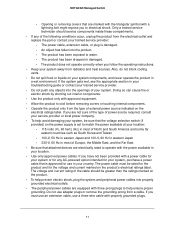
... electrical ratings label. If you must be sure that are electrically rated to water. - Opening or removing covers that the voltage selection switch (if provided) on the electrical ratings label. The power cable, extension cable, or plug is approved for your country. If the system... electrical outlet and replace the part or contact your system away from radiators and heat sources. Do not use in a wet environment. NETGEAR Managed Switch - If you are equipped with three-prong plugs to electrical shock. Also, do not block cooling vents. • Do not spill...
... electrical ratings label. If you must be sure that are electrically rated to water. - Opening or removing covers that the voltage selection switch (if provided) on the electrical ratings label. The power cable, extension cable, or plug is approved for your country. If the system... electrical outlet and replace the part or contact your system away from radiators and heat sources. Do not use in a wet environment. NETGEAR Managed Switch - If you are equipped with three-prong plugs to electrical shock. Also, do not block cooling vents. • Do not spill...

Hardware Installation Guide
Page 12
...; Consult a licensed electrician or your power company for the extension cable or power strip. • To help protect your local and national wiring rules. 12 NETGEAR Managed Switch • Observe extension cable and power strip ratings. Make sure that nothing rests on or tripped over.
...; Consult a licensed electrician or your power company for the extension cable or power strip. • To help protect your local and national wiring rules. 12 NETGEAR Managed Switch • Observe extension cable and power strip ratings. Make sure that nothing rests on or tripped over.

Hardware Installation Guide
Page 13
... contains the following items: • Managed stackable switch with preinstalled software • Power cord • Rubber footpads for tabletop installation • Rubber caps for the SFP sockets • Rack-mounting kit • Wall-mounting kit (M4100-D10-POE, M4100-D12G, and M4100-D12G-POE+ only) • Magnetic mounting kit (M4100-D10-POE and M4100-D12G only) • USB console cable...
... contains the following items: • Managed stackable switch with preinstalled software • Power cord • Rubber footpads for tabletop installation • Rubber caps for the SFP sockets • Rack-mounting kit • Wall-mounting kit (M4100-D10-POE, M4100-D12G, and M4100-D12G-POE+ only) • Magnetic mounting kit (M4100-D10-POE and M4100-D12G only) • USB console cable...

Hardware Installation Guide
Page 14
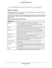
...Inspect the products and accessories for replacement. 5. Report any item is missing or damaged, contact your body. 2. Just before installing the switch. 1. Place the container on a secure and clean surface. Unpack the hardware from electrostatic discharge (ESD): 1. For more information, ...and cut all sensitive components in this section: 1. Select a location. NETGEAR Managed Switch You can also take the following steps to install it. When unpacking a static-sensitive component from your local NETGEAR reseller for damage. Make sure that all packing material. 4. Apply ...
...Inspect the products and accessories for replacement. 5. Report any item is missing or damaged, contact your body. 2. Just before installing the switch. 1. Place the container on a secure and clean surface. Unpack the hardware from electrostatic discharge (ESD): 1. For more information, ...and cut all sensitive components in this section: 1. Select a location. NETGEAR Managed Switch You can also take the following steps to install it. When unpacking a static-sensitive component from your local NETGEAR reseller for damage. Make sure that all packing material. 4. Apply ...
Hardware Installation Guide
Page 15
...-45 ports, view the front panel LEDs, and access the rear panel power connector. Keep the switch away from strong electromagnetic field generators (such as motors), vibration, dust, and direct exposure to 122ºF). NETGEAR Managed Switch For more information, see Connect to avoid sources of electrical noise such as radio transmitters, broadcast amplifiers...
...-45 ports, view the front panel LEDs, and access the rear panel power connector. Keep the switch away from strong electromagnetic field generators (such as motors), vibration, dust, and direct exposure to 122ºF). NETGEAR Managed Switch For more information, see Connect to avoid sources of electrical noise such as radio transmitters, broadcast amplifiers...

Hardware Installation Guide
Page 16
... airflow and ease in a rack you install your switch: • Ambient operating temperature. To install your switch. NETGEAR Managed Switch Install the Switch You can install the switch on overcurrent protection and power supply wiring. To install the switch in servicing. Mount the equipment into a rack so... times. If the switch is not compromised. • Mechanical loading. Mount the equipment into a rack so that any possible overloading of the rack environment might have on a flat surface or in a Rack Note: The M4100-D10-PoE, M4100-D12G, and M4100-D12G-POE+ are not...
... airflow and ease in a rack you install your switch: • Ambient operating temperature. To install your switch. NETGEAR Managed Switch Install the Switch You can install the switch on overcurrent protection and power supply wiring. To install the switch in servicing. Mount the equipment into a rack so... times. If the switch is not compromised. • Mechanical loading. Mount the equipment into a rack so that any possible overloading of the rack environment might have on a flat surface or in a Rack Note: The M4100-D10-PoE, M4100-D12G, and M4100-D12G-POE+ are not...

Hardware Installation Guide
Page 17
Align the bracket and rack holes. Hardware Installation 17 Use the provided Phillips head screws to fasten the brackets to secure each bracket to secure the switch in the rack. Tighten the screws with nylon washers to fasten each bracket. 4. NETGEAR Managed Switch 2. Use two pan-head screws with a No. 2 Phillips screwdriver to the rack. 5. Tighten the screws with a No. 1 Phillips screwdriver to the sides of the switch. M4100-24G-POE+ Mounting bracket 3.
Align the bracket and rack holes. Hardware Installation 17 Use the provided Phillips head screws to fasten the brackets to secure each bracket to secure the switch in the rack. Tighten the screws with nylon washers to fasten each bracket. 4. NETGEAR Managed Switch 2. Use two pan-head screws with a No. 2 Phillips screwdriver to the rack. 5. Tighten the screws with a No. 1 Phillips screwdriver to the sides of the switch. M4100-24G-POE+ Mounting bracket 3.
Hardware Installation Guide
Page 18
... the position of clearance on the wall. 5. Tighten the screws with the ports to the wall. Note: The switch should have a minimum of 5 inches (130 millimeters) of bracket holes on all sides. 1. Tighten the screws with a No. 1 Phillips ... screws to the wall. 8. The switch should come out the side of the switch. 3. Attach the supplied mounting brackets to orient the switch as shown in the following figure. NETGEAR Managed Switch Install the Switch on a Wall (M4100-D12G, M4100-D10-PoE, and M4100-D12G-POE+ Only) If you install the switch on a wall in the vertical position...
... the position of clearance on the wall. 5. Tighten the screws with the ports to the wall. Note: The switch should have a minimum of 5 inches (130 millimeters) of bracket holes on all sides. 1. Tighten the screws with a No. 1 Phillips ... screws to the wall. 8. The switch should come out the side of the switch. 3. Attach the supplied mounting brackets to orient the switch as shown in the following figure. NETGEAR Managed Switch Install the Switch on a Wall (M4100-D12G, M4100-D10-PoE, and M4100-D12G-POE+ Only) If you install the switch on a wall in the vertical position...
Hardware Installation Guide
Page 19
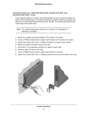
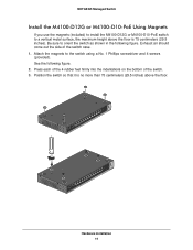
... Installation 19 Attach the magnets to the switch using a No. 1 Phillips screwdriver and 4 screws (provided). Press each of the 4 rubber feet firmly into the indentations on the bottom of the switch case. 1. NETGEAR Managed Switch Install the M4100-D12G or M4100-D10-PoE Using Magnets If you use the... magnets (included) to install the M4100-D12G or M4100-D10-PoE switch to a vertical metal surface, the maximum height above the ...
... Installation 19 Attach the magnets to the switch using a No. 1 Phillips screwdriver and 4 screws (provided). Press each of the 4 rubber feet firmly into the indentations on the bottom of the switch case. 1. NETGEAR Managed Switch Install the M4100-D12G or M4100-D10-PoE Using Magnets If you use the... magnets (included) to install the M4100-D12G or M4100-D10-PoE switch to a vertical metal surface, the maximum height above the ...

Hardware Installation Guide
Page 20
NETGEAR Managed Switch Check the Installation Before you connect the power cord, select an AC outlet that is not controlled by a wall switch (which can turn off switch. Connect port 1 of the switch. Check cable routing to the switch). Connect to Power and Check the LEDs The switch ...cables are installed correctly. 3. Select an appropriate outlet. 2. Note: Normally the M4100-D12G and M4100-D12G-POE+ will not create a safety hazard. 4. If the PSE device used does not support IEEE802.3at, theses switches might not operate correctly. 3. Check the Power LED on self-test (POST)....
NETGEAR Managed Switch Check the Installation Before you connect the power cord, select an AC outlet that is not controlled by a wall switch (which can turn off switch. Connect port 1 of the switch. Check cable routing to the switch). Connect to Power and Check the LEDs The switch ...cables are installed correctly. 3. Select an appropriate outlet. 2. Note: Normally the M4100-D12G and M4100-D12G-POE+ will not create a safety hazard. 4. If the PSE device used does not support IEEE802.3at, theses switches might not operate correctly. 3. Check the Power LED on self-test (POST)....

Hardware Installation Guide
Page 21
..., see Troubleshooting on the front panel of the M4100-D12G and M4100-D12G-POE+ blinks green, port 1 is good. If the Power LED does not light up, check that the power cable is plugged in correctly and that it supports IEEE802.3at. Insert the module into the switch's ports. Press firmly to make sure that... standard • AFM735: SFP module with LC connector, compatible with the IEEE 802.3u 100Base-FX standard To insert an SFP module into the connector. NETGEAR Managed Switch • If the POST fails, the Power LED blinks yellow. Note: If the PD LED on page 24.
..., see Troubleshooting on the front panel of the M4100-D12G and M4100-D12G-POE+ blinks green, port 1 is good. If the Power LED does not light up, check that the power cable is plugged in correctly and that it supports IEEE802.3at. Insert the module into the switch's ports. Press firmly to make sure that... standard • AFM735: SFP module with LC connector, compatible with the IEEE 802.3u 100Base-FX standard To insert an SFP module into the connector. NETGEAR Managed Switch • If the POST fails, the Power LED blinks yellow. Note: If the PD LED on page 24.
Hardware Installation Guide
Page 22
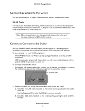
... the DB9 (cable included) as the console port by pushing the slide switch to attach devices using either straight-through the console slide switch on the rear of the switch, or connect the USB console cable to the switch: 1. NETGEAR Managed Switch Connect Equipment to the Switch You can connect devices, a Gigabit Ethernet module, and/or a console to...
... the DB9 (cable included) as the console port by pushing the slide switch to attach devices using either straight-through the console slide switch on the rear of the switch, or connect the USB console cable to the switch: 1. NETGEAR Managed Switch Connect Equipment to the Switch You can connect devices, a Gigabit Ethernet module, and/or a console to...


