Hardware Installation Guide
Page 1
Managed Switch Hardware Installation Guide Models: M4100 Series 350 East Plumeria Drive San Jose, CA 95134 USA November 2013 202-11217-02 v1.0
Managed Switch Hardware Installation Guide Models: M4100 Series 350 East Plumeria Drive San Jose, CA 95134 USA November 2013 202-11217-02 v1.0
Hardware Installation Guide
Page 2
..., and Auto Uplink are registered trademarks of Microsoft Corporation. You must register your product before you for selecting NETGEAR products. Microsoft, Windows, Windows NT, and Vista are trademarks or registered trademarks of phone numbers at https://my.netgear.com. NETGEAR Managed Switch Support Thank you can use it to register your product and use...
..., and Auto Uplink are registered trademarks of Microsoft Corporation. You must register your product before you for selecting NETGEAR products. Microsoft, Windows, Windows NT, and Vista are trademarks or registered trademarks of phone numbers at https://my.netgear.com. NETGEAR Managed Switch Support Thank you can use it to register your product and use...
Hardware Installation Guide
Page 3
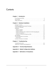
... Package Contents 13 Protecting against Electrostatic Discharge 13 Unpack the Hardware 14 Installation 14 Select a Location 15 Install the Switch 16 Install the M4100-D12G or M4100-D10-PoE Using Magnets 19 Check the Installation 20 Connect to Power and Check the LEDs 20 SFP Modules 21 ...Connect Equipment to the Switch 22 RJ-45 Ports 22 Connect a Console to the Switch 22 Chapter 3 Troubleshooting Troubleshooting Chart 24 Additional ...
... Package Contents 13 Protecting against Electrostatic Discharge 13 Unpack the Hardware 14 Installation 14 Select a Location 15 Install the Switch 16 Install the M4100-D12G or M4100-D10-PoE Using Magnets 19 Check the Installation 20 Connect to Power and Check the LEDs 20 SFP Modules 21 ...Connect Equipment to the Switch 22 RJ-45 Ports 22 Connect a Console to the Switch 22 Chapter 3 Troubleshooting Troubleshooting Chart 24 Additional ...

Hardware Installation Guide
Page 4
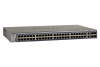
For information about features for these managed switches. Introduction 1 The NETGEAR ProSafe® 4100 series managed switches provide state-of the ProSafe 4100 series managed switches. Front Panels and LEDs The following : M4100-26G M4100-50G M4100-26-POE M4100-26G-POE M4100-50G-POE+ M4100-50-POE M4100-D10-POE M4100-D12G M4100-12GF M4100-D12G-POE+ M4100-24G-POE+ M4100-12G-POE+ This guide describes hardware installation...
For information about features for these managed switches. Introduction 1 The NETGEAR ProSafe® 4100 series managed switches provide state-of the ProSafe 4100 series managed switches. Front Panels and LEDs The following : M4100-26G M4100-50G M4100-26-POE M4100-26G-POE M4100-50G-POE+ M4100-50-POE M4100-D10-POE M4100-D12G M4100-12GF M4100-D12G-POE+ M4100-24G-POE+ M4100-12G-POE+ This guide describes hardware installation...

Hardware Installation Guide
Page 5
M4100-50-POE front panel POE ports RJ-45 ports SFP ports 5 M4100-50G front panel RJ-45 ports SFP SPD/Link/ACT mode: Green = Link at 1G Yellow = Link at 100M Blink = ACT SFP ports LEDs USB port Reset button Figure 3. M4100-26-POE front panel POE ports RJ-45 ports SFP ports LEDs USB port Reset button Figure 4. NETGEAR Managed Switch LEDs USB port Reset button Figure 1. M4100-26G front panel RJ-45 ports SFP ports Combo Ports Power Fan RPS Reset USB RJ45 SPD/Link/ACT mode: Green = 1G Yellow = 10/100M Blink = ACT LEDs USB port Reset button Figure 2.
M4100-50-POE front panel POE ports RJ-45 ports SFP ports 5 M4100-50G front panel RJ-45 ports SFP SPD/Link/ACT mode: Green = Link at 1G Yellow = Link at 100M Blink = ACT SFP ports LEDs USB port Reset button Figure 3. M4100-26-POE front panel POE ports RJ-45 ports SFP ports LEDs USB port Reset button Figure 4. NETGEAR Managed Switch LEDs USB port Reset button Figure 1. M4100-26G front panel RJ-45 ports SFP ports Combo Ports Power Fan RPS Reset USB RJ45 SPD/Link/ACT mode: Green = 1G Yellow = 10/100M Blink = ACT LEDs USB port Reset button Figure 2.

Hardware Installation Guide
Page 7
... Yellow = PoE Fault PoE SPD/Link/ACT RJ45 SPD/Link/ACT mode: Green = 1G Yellow = 10/100M Blink = ACT LEDs USB port Reset button Figure 9. NETGEAR Managed Switch Power Fan PD MaxPoE Reset USB PoE (Max 30W per port): Off = No PD Green = PoE Powered Yellow = PoE Fault PoE-PD (Port 1, 2): Off... Green = PoE Powered Yellow = PoE Fault PoE SPD/Link/ACT RJ45 SPD/Link/ACT mode: Green = 1G Yellow = 10/100M Blink = ACT SPD/Link/ACT M4100-12G-POE+ SFP SPD/Link/ACT mode Green = Link at 1G Yellow = Link at 100M Blink = ACT USB DB9 Console(USB) 115200,N,8,1 POE ports Console...
... Yellow = PoE Fault PoE SPD/Link/ACT RJ45 SPD/Link/ACT mode: Green = 1G Yellow = 10/100M Blink = ACT LEDs USB port Reset button Figure 9. NETGEAR Managed Switch Power Fan PD MaxPoE Reset USB PoE (Max 30W per port): Off = No PD Green = PoE Powered Yellow = PoE Fault PoE-PD (Port 1, 2): Off... Green = PoE Powered Yellow = PoE Fault PoE SPD/Link/ACT RJ45 SPD/Link/ACT mode: Green = 1G Yellow = 10/100M Blink = ACT SPD/Link/ACT M4100-12G-POE+ SFP SPD/Link/ACT mode Green = Link at 1G Yellow = Link at 100M Blink = ACT USB DB9 Console(USB) 115200,N,8,1 POE ports Console...

Hardware Installation Guide
Page 8
... specified power. Off: PD port 1 is at ) 8 Off: There is not connected to the switch. Solid yellow: A valid 10/100 Mbps link is established on the port. Short circuit on the port. NETGEAR Managed Switch Table 1. LED descriptions LED Power Fan RPS PD Max PoE SPD/Link/ACT (RJ-45 port... green: The PoE powered device (PD) is connected and the port is disconnected. Note: Only for M4100-26G, 50G, 26-POE, 26G-POE, 50G-POE+, and 50-POE Solid green: PD port 1 is available. Note: Only for M4100-D12G, -24G-POE, D12G-POE, 12G-POE+, -12GF Solid yellow: Indicates less than 7 watts...
... specified power. Off: PD port 1 is at ) 8 Off: There is not connected to the switch. Solid yellow: A valid 10/100 Mbps link is established on the port. Short circuit on the port. NETGEAR Managed Switch Table 1. LED descriptions LED Power Fan RPS PD Max PoE SPD/Link/ACT (RJ-45 port... green: The PoE powered device (PD) is connected and the port is disconnected. Note: Only for M4100-26G, 50G, 26-POE, 26G-POE, 50G-POE+, and 50-POE Solid green: PD port 1 is available. Note: Only for M4100-D12G, -24G-POE, D12G-POE, 12G-POE+, -12GF Solid yellow: Indicates less than 7 watts...

Hardware Installation Guide
Page 9
... PSE successfully. LED descriptions (Continued) LED Link/ACT (RJ45 port) SPD (RJ45 port) Description Off: No link is established on the port. NETGEAR Managed Switch Table 1. Solid yellow: A valid 10/100 Mbps link is established on the port. PoE-PD Off: No PSE is connected or PSE is ...established on the port at 1000 Mbps. Solid yellow: A valid 100 Mbps SFP module link is connected but connection has failed. M4100-26G, 50G, 26-POE, 26G-POE, 50G...
... PSE successfully. LED descriptions (Continued) LED Link/ACT (RJ45 port) SPD (RJ45 port) Description Off: No link is established on the port. NETGEAR Managed Switch Table 1. Solid yellow: A valid 10/100 Mbps link is established on the port. PoE-PD Off: No PSE is connected or PSE is ...established on the port at 1000 Mbps. Solid yellow: A valid 100 Mbps SFP module link is connected but connection has failed. M4100-26G, 50G, 26-POE, 26G-POE, 50G...

Hardware Installation Guide
Page 10
... panel AC power connector Safety Instructions Use the following precautions. • Observe and follow service markings. - M4100-12GF, 24G-POE+, 12G-POE+ rear panel AC power connector Lock Console port Figure 16. NETGEAR Managed Switch Console switch Console ports Lock Power adapter connector Figure 14. To reduce the risk of bodily injury, electrical shock...
... panel AC power connector Safety Instructions Use the following precautions. • Observe and follow service markings. - M4100-12GF, 24G-POE+, 12G-POE+ rear panel AC power connector Lock Console port Figure 16. NETGEAR Managed Switch Console switch Console ports Lock Power adapter connector Figure 14. To reduce the risk of bodily injury, electrical shock...
Hardware Installation Guide
Page 11
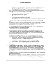
NETGEAR Managed Switch - Opening or removing covers that is approved for the voltage and current marked on the product's electrical ratings label. The power cable, extension cable, or ... following conditions occur, unplug the product from the type of Europe, the Middle East, and the Far East • Be sure that the voltage selection switch (if provided) on your system components, and never operate the product in your system. Only a trained service technician should be rated for the product and...
NETGEAR Managed Switch - Opening or removing covers that is approved for the voltage and current marked on the product's electrical ratings label. The power cable, extension cable, or ... following conditions occur, unplug the product from the type of Europe, the Middle East, and the Far East • Be sure that the voltage selection switch (if provided) on your system components, and never operate the product in your system. Only a trained service technician should be rated for the product and...

Hardware Installation Guide
Page 12
Consult a licensed electrician or your power company for the extension cable or power strip. • To help protect your local and national wiring rules. 12 NETGEAR Managed Switch • Observe extension cable and power strip ratings. Make sure that nothing rests on or tripped over. Be sure that the total ampere rating of...
Consult a licensed electrician or your power company for the extension cable or power strip. • To help protect your local and national wiring rules. 12 NETGEAR Managed Switch • Observe extension cable and power strip ratings. Make sure that nothing rests on or tripped over. Be sure that the total ampere rating of...

Hardware Installation Guide
Page 13
... discharge static electricity from your system. Hardware Installation 2 This chapter explains how to access them: - ProSafe M4100 and M7100 Managed Switches Software Administration Manual - You can harm delicate components inside your body before you touch any of the electronic...; Resource CD: The CD includes either these documents or links to install the hardware for the managed switches. ProSafe M4100 Managed Switch Installation Guide - ProSafe Managed Switch Command-Line Interface (CLI) User Manual - This hardware installation guide • ProSafe NMS200 Network Management ...
... discharge static electricity from your system. Hardware Installation 2 This chapter explains how to access them: - ProSafe M4100 and M7100 Managed Switches Software Administration Manual - You can harm delicate components inside your body before you touch any of the electronic...; Resource CD: The CD includes either these documents or links to install the hardware for the managed switches. ProSafe M4100 Managed Switch Installation Guide - ProSafe Managed Switch Command-Line Interface (CLI) User Manual - This hardware installation guide • ProSafe NMS200 Network Management ...

Hardware Installation Guide
Page 14
...If possible, use antistatic floor pads, workbench pads, and an antistatic grounding strap. Install the switch. Just before installing the switch. 1. Select a location. For more information, see Install the Switch on page 15. 3. Unpack the Hardware Check the contents of the boxes to prevent damage from... electrostatic discharge (ESD): 1. Carefully remove the hardware and place it in a static-safe area. NETGEAR Managed Switch You can also take the following steps to make sure that all items are present before unwrapping the antistatic package, discharge...
...If possible, use antistatic floor pads, workbench pads, and an antistatic grounding strap. Install the switch. Just before installing the switch. 1. Select a location. For more information, see Install the Switch on page 15. 3. Unpack the Hardware Check the contents of the boxes to prevent damage from... electrostatic discharge (ESD): 1. Carefully remove the hardware and place it in a static-safe area. NETGEAR Managed Switch You can also take the following steps to make sure that all items are present before unwrapping the antistatic package, discharge...
Hardware Installation Guide
Page 15
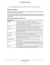
...the installation location. Install the switch in a dry area with your switch. Install the switch in a site free from heat sources such as direct sunlight, warm air exhausts, hot-air vents, and heaters. Route the cable to the outlet and the switch. NETGEAR Managed Switch For more information, see ...Connect to Power and Check the LEDs on all sides for cooling. Site requirements for the switch are shown in a standard 19-inch (48.26-centimeter) rack, wall...
...the installation location. Install the switch in a dry area with your switch. Install the switch in a site free from heat sources such as direct sunlight, warm air exhausts, hot-air vents, and heaters. Route the cable to the outlet and the switch. NETGEAR Managed Switch For more information, see ...Connect to Power and Check the LEDs on all sides for cooling. Site requirements for the switch are shown in a standard 19-inch (48.26-centimeter) rack, wall...

Hardware Installation Guide
Page 16
... airflow and ease in a standard 19-inch rack. NETGEAR Managed Switch Install the Switch You can install the switch on a flat surface or in servicing. Install the Switch in an environment compatible with your switch. Therefore, consider installing the equipment in a Rack Note: The M4100-D10-PoE, M4100-D12G, and M4100-D12G-POE+ are not rack mountable. To ensure...
... airflow and ease in a standard 19-inch rack. NETGEAR Managed Switch Install the Switch You can install the switch on a flat surface or in servicing. Install the Switch in an environment compatible with your switch. Therefore, consider installing the equipment in a Rack Note: The M4100-D10-PoE, M4100-D12G, and M4100-D12G-POE+ are not rack mountable. To ensure...

Hardware Installation Guide
Page 17
Tighten the screws with a No. 1 Phillips screwdriver to secure each bracket to secure the switch in the rack. Use two pan-head screws with a No. 2 Phillips screwdriver to the rack. 5. Hardware Installation 17 Use the provided Phillips head screws to fasten the brackets to fasten each bracket. 4. Align the bracket and rack holes. Tighten the screws with nylon washers to the sides of the switch. M4100-24G-POE+ Mounting bracket 3. NETGEAR Managed Switch 2.
Tighten the screws with a No. 1 Phillips screwdriver to secure each bracket to secure the switch in the rack. Use two pan-head screws with a No. 2 Phillips screwdriver to the rack. 5. Hardware Installation 17 Use the provided Phillips head screws to fasten the brackets to fasten each bracket. 4. Align the bracket and rack holes. Tighten the screws with nylon washers to the sides of the switch. M4100-24G-POE+ Mounting bracket 3. NETGEAR Managed Switch 2.
Hardware Installation Guide
Page 18
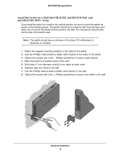
...clearance on all sides. 1. Attach the supplied mounting brackets to fasten each mark. 6. Note: The switch should come out the side of the switch. 2. Do not mount the switch with a No. 1 Phillips screwdriver to secure each bracket to the side. Tighten the screws with ...No. 2 Phillips screwdriver to secure the switch to the wall. 8. Hardware Installation 18 Hammer caps into holes in the following figure. NETGEAR Managed Switch Install the Switch on a Wall (M4100-D12G, M4100-D10-PoE, and M4100-D12G-POE+ Only) If you install the switch on a wall in the vertical position...
...clearance on all sides. 1. Attach the supplied mounting brackets to fasten each mark. 6. Note: The switch should come out the side of the switch. 2. Do not mount the switch with a No. 1 Phillips screwdriver to secure each bracket to the side. Tighten the screws with ...No. 2 Phillips screwdriver to secure the switch to the wall. 8. Hardware Installation 18 Hammer caps into holes in the following figure. NETGEAR Managed Switch Install the Switch on a Wall (M4100-D12G, M4100-D10-PoE, and M4100-D12G-POE+ Only) If you install the switch on a wall in the vertical position...
Hardware Installation Guide
Page 19
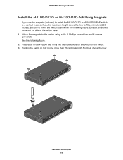
...29.5 inches). Attach the magnets to orient the switch as shown in the following figure. 2. Press each of the 4 rubber feet firmly into the indentations on the bottom of the switch case. 1. NETGEAR Managed Switch Install the M4100-D12G or M4100-D10-PoE Using Magnets If you use the magnets... (included) to install the M4100-D12G or M4100-D10-PoE switch to a vertical metal surface, the maximum height above the floor...
...29.5 inches). Attach the magnets to orient the switch as shown in the following figure. 2. Press each of the 4 rubber feet firmly into the indentations on the bottom of the switch case. 1. NETGEAR Managed Switch Install the M4100-D12G or M4100-D10-PoE Using Magnets If you use the magnets... (included) to install the M4100-D12G or M4100-D10-PoE switch to a vertical metal surface, the maximum height above the floor...

Hardware Installation Guide
Page 20
...Supported RPS models are installed correctly. 3. If the PSE device used does not support IEEE802.3at, theses switches might not operate correctly. 3. The switch is to pass data. NETGEAR Managed Switch Check the Installation Before you connect the power cord, select an AC outlet that all cables are the ... power using the supplied power adapter. To apply AC power: 1. Note: The M4100-26G, 50G, 26-PoE, 26G-PoE, 50-PoE+, 50G-PoE, 12GF, 24G-POE+, 12G-POE+ can provide full power to these switches to ensure that all equipment is not available. The PSE device should light in...
...Supported RPS models are installed correctly. 3. If the PSE device used does not support IEEE802.3at, theses switches might not operate correctly. 3. The switch is to pass data. NETGEAR Managed Switch Check the Installation Before you connect the power cord, select an AC outlet that all cables are the ... power using the supplied power adapter. To apply AC power: 1. Note: The M4100-26G, 50G, 26-PoE, 26G-PoE, 50-PoE+, 50G-PoE, 12GF, 24G-POE+, 12G-POE+ can provide full power to these switches to ensure that all equipment is not available. The PSE device should light in...

Hardware Installation Guide
Page 21
NETGEAR Managed Switch • If the POST fails, the Power LED blinks yellow. For more information, see Troubleshooting on the front panel of the M4100-D12G and M4100-D12G-POE+ blinks green, port 1 is connected to a IEEE802.3af PoE device. Insert the module into the switch's ports. Press firmly to... make sure that the module seats into the switch port: 1. Check the PoE device specification...
NETGEAR Managed Switch • If the POST fails, the Power LED blinks yellow. For more information, see Troubleshooting on the front panel of the M4100-D12G and M4100-D12G-POE+ blinks green, port 1 is connected to a IEEE802.3af PoE device. Insert the module into the switch's ports. Press firmly to... make sure that the module seats into the switch port: 1. Check the PoE device specification...


